Tools Required
J 45722 Fuel Sender Lock Ring Wrench
Removal Procedure
- Remove the fuel tank assembly. Refer to Fuel Tank Replacement .
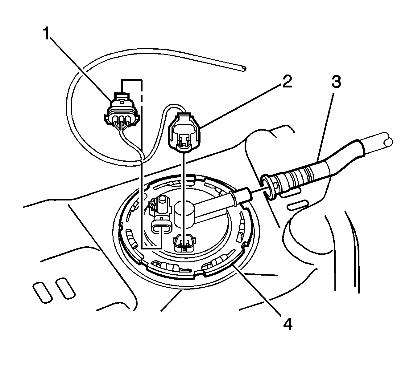
- Disconnect the fuel tank pressure sensor connector (1), the fuel pump connector (2), and the EVAP vapor hose quick connector (3), from the modular fuel pump and sender assembly cover (4).
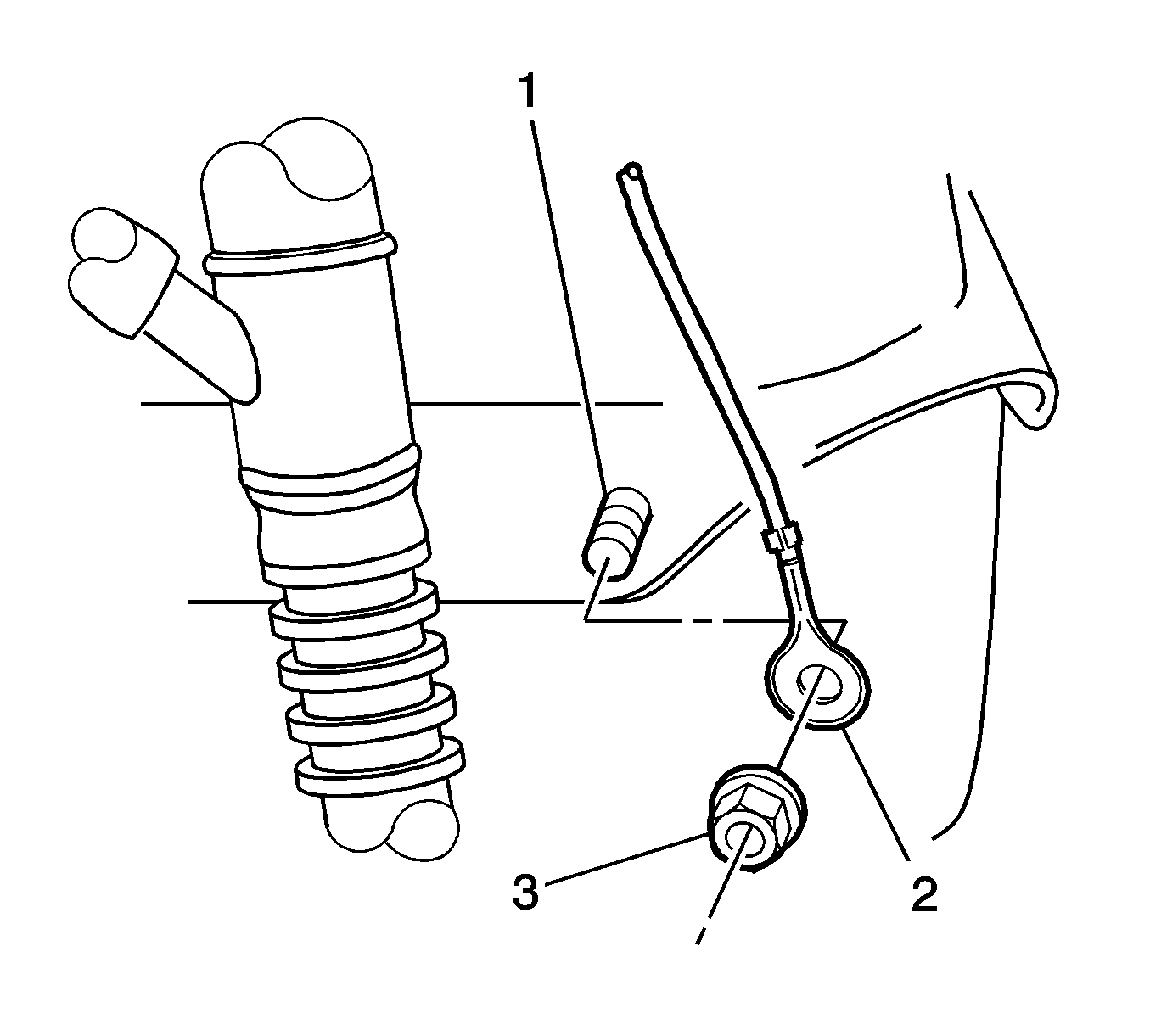
- Remove the flanged nut (3) securing the modular fuel pump and sender assembly ground terminal (2) to the fuel tank flange stud (1), and remove the fuel tank wiring harness.
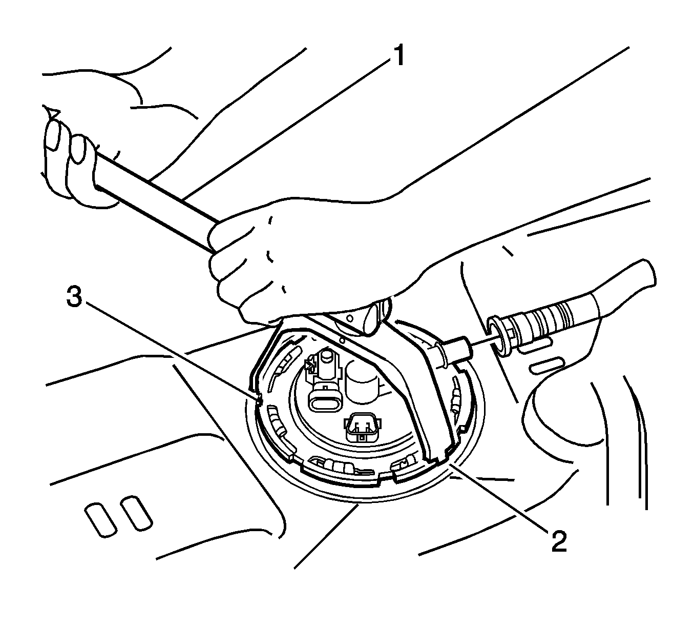
- Using the J 45722 (2) and a half-inch breaker bar (1), remove the cover retainer lock ring (3) by turning in a counterclockwise direction.
- Partially lift the modular fuel pump and sender assembly away from the fuel tank, taking care not to damage the fuel level sender assembly.
- Disconnect the fuel tank evaporative emission (EVAP) vapor line quick connector from the underside of the modular fuel pump and sender assembly cover.
- Insert hand into the fuel tank opening and disconnect the fuel feed line quick connector.
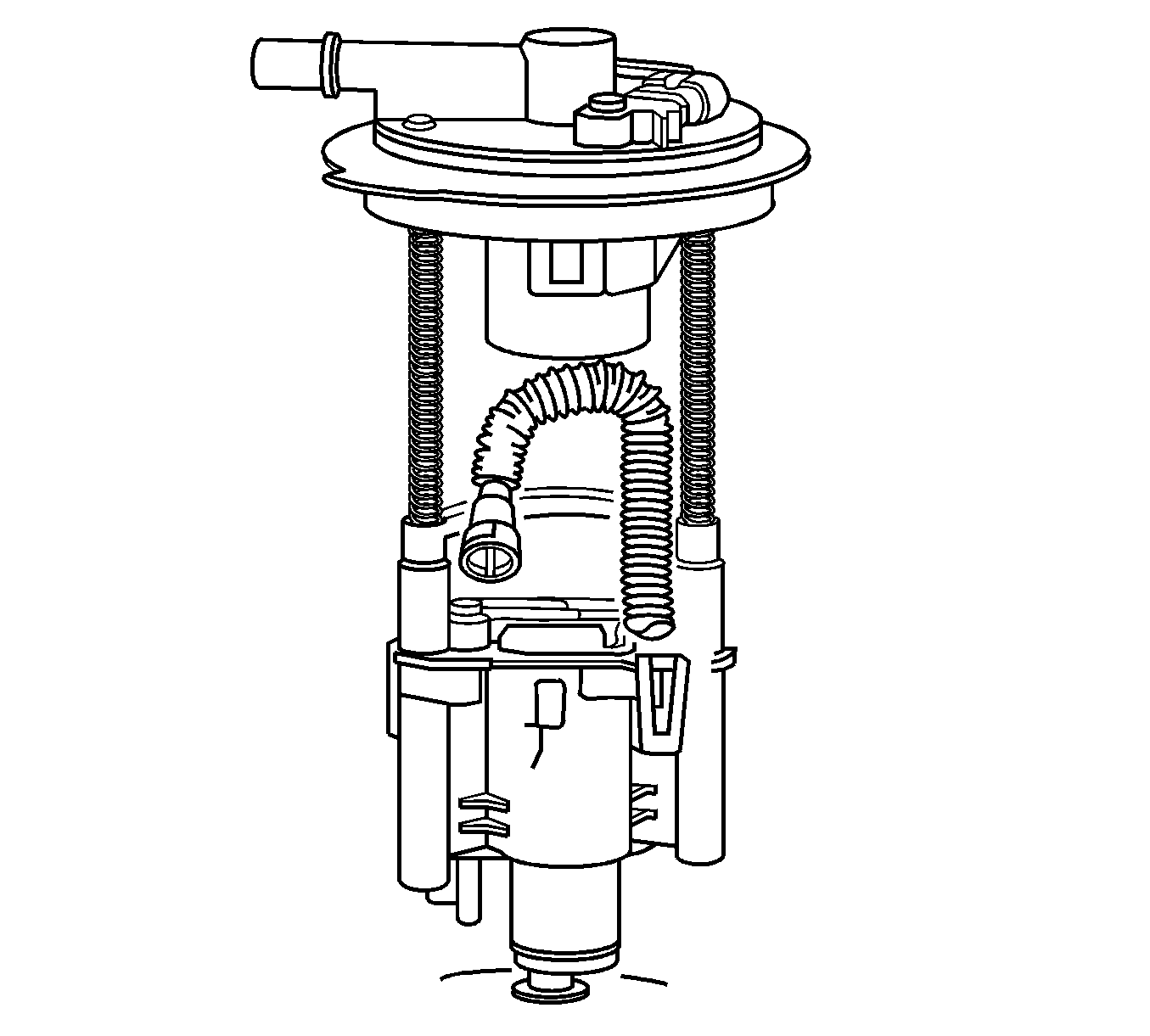
- Remove the modular fuel pump and sender assembly.
- Remove and discard the modular fuel pump and sender assembly to fuel tank seal.
- Place the lock ring on a flat surface. Measure the clearance between the lock ring and the flat surface using a feeler gage at 7 points.
- If warpage is less than 0.41 mm (0.016 in), the lock ring does not require replacement.
- If warpage is greater than 0.41 mm (0.016 in), the lock ring must be replaced.
Notice: Avoid damaging the lock ring. Use only J-45722 to prevent damage to the lock ring.
Notice: Do Not handle the fuel sender assembly by the fuel pipes. The amount of leverage generated by handling the fuel pipes could damage the joints.
Important: Do NOT use impact tools. Significant force will be required to release the lock ring. The use of a hammer and screwdriver is not recommended. Secure the fuel tank in order to prevent fuel tank rotation.
Important:
• Fuel vapor remains in the tank even when completely empty. Seal the opening in the fuel tank using a suitable plug and place a suitable cover over the plug to prevent any foreign matter from entering • Check the underside of the reservoir to ensure that there are 3 rubber isolator feet attached to the bottom. If one or more are missing, retrieve each from within the fuel tank and reinstall
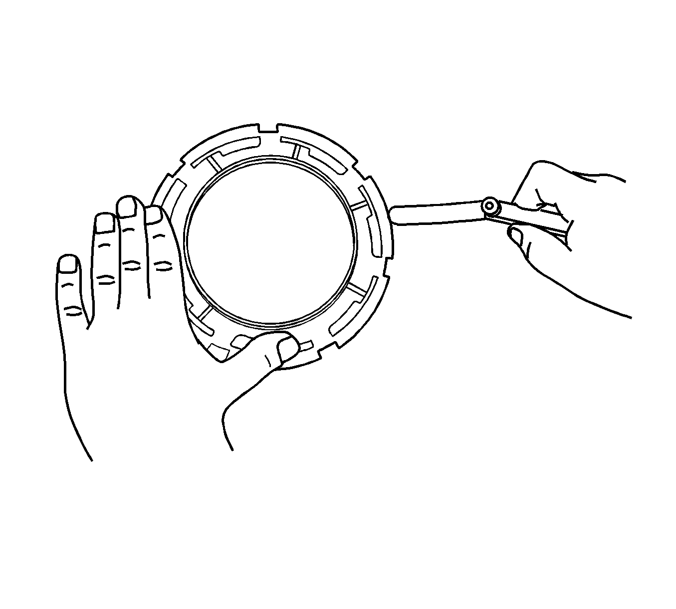
Important:
• Some lock rings were manufactured with "DO NOT REUSE" stamped into them. These lock rings may be reused if they are not damaged or warped. • Inspect the lock ring for damage due to improper removal or installation procedures. If damage is found, install a NEW lock ring. • Check the lock ring for flatness.
Installation Procedure
- Before installation into the fuel tank, check the fuel sender float position.
- Clean any dirt and foreign materials from the fuel tank seal recess and position a new seal in the recess.
- Install the modular fuel pump and sender assembly into the fuel tank, taking care not to damage the fuel level sender float and arm in the process.
- Insert hand into the fuel tank opening and connect the fuel feed line quick connector.
- Connect the fuel tank EVAP vapor line quick connector from the underside of the modular fuel pump and sender assembly cover.
- Ensure the locator in the cover engages in the slot in the tank opening.
- Install the cover retainer lock ring. Use the half-inch breaker bar with J 45722 and rotate the retainer in a clockwise direction until the tangs are engaged.
- Install the fuel tank wiring harness, and the flanged nut (3) securing the modular fuel pump and sender assembly ground terminal (2) to the fuel tank flange stud (1).
- Install the fuel tank pressure sensor connector (1), the fuel pump connector (2), and the EVAP vapor hose quick connector (3) to the modular fuel pump and sender assembly cover (4).
- Install the fuel tank assembly. Refer to Fuel Tank Replacement .
Important: Upon installation of the modular fuel pump and sender assembly, only use the custom sized O-rings as supplied with modular fuel pump and sender assembly replacement parts kit. Do not use off-the-shelf O-rings.
| • | Stand the assembly upright on a flat surface. |
| • | Measure the distance between the middle of the fuel sender float and the flat surface. |
| • | If required, the float position should be corrected, through careful adjustment of the float arm. |
Float Position
7-14 mm.
Important: Always replace the fuel sender seal when installing the fuel sender assembly. Replace the lock ring if necessary. DO NOT apply any type of lubrication in the seal groove.
Ensure the lock ring is installed with the correct side facing upward. A correctly installed lock ring will only turn in a clockwise direction.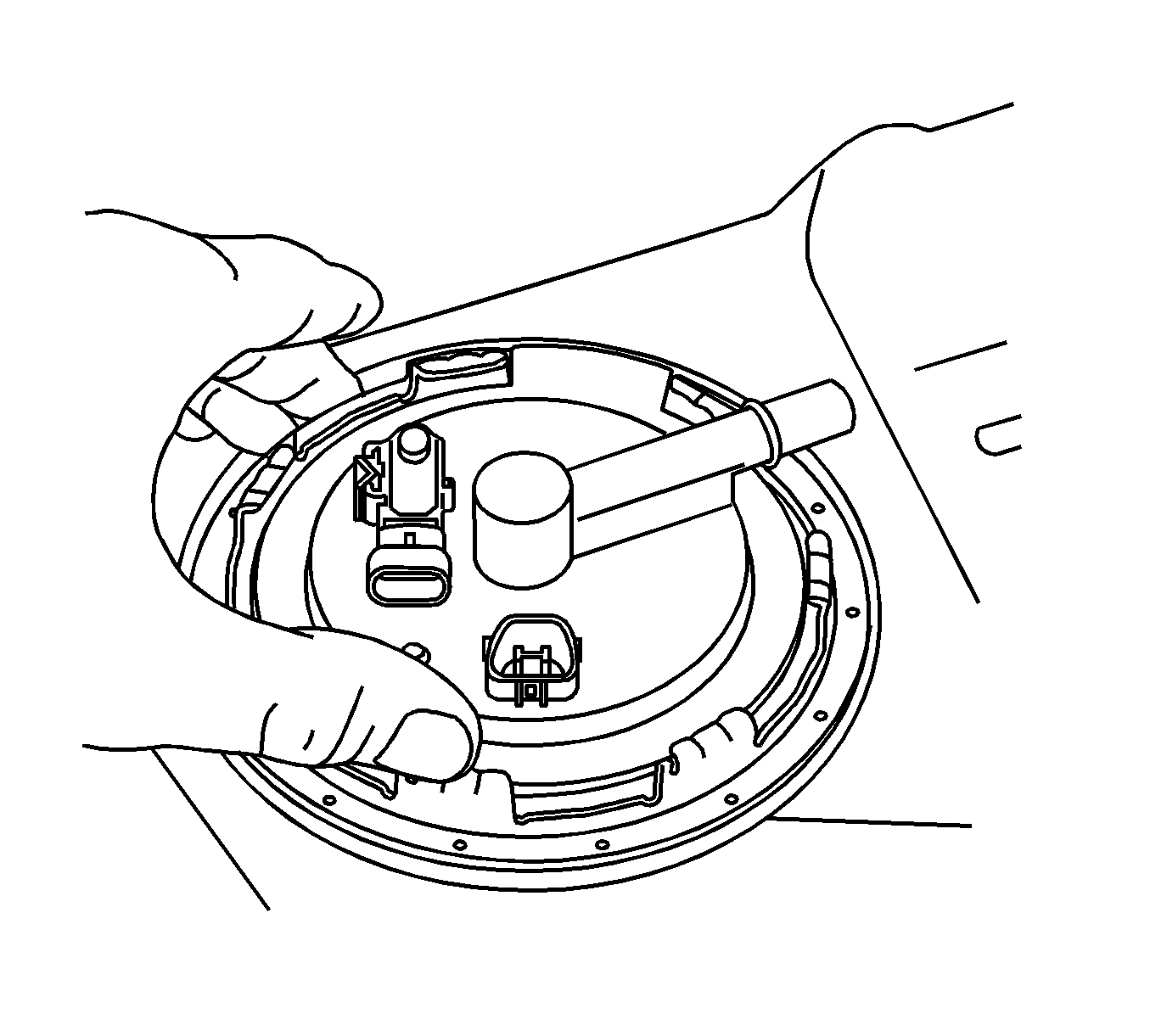

Notice: Refer to Fastener Notice in the Preface section.

Tighten
Tighten the flange nut to 7 N·m (62 lb in).

