Tools Required
J 45059 Angle Meter
Removal Procedure
- LOCK the steering column and verify the front wheels are in the straight ahead position.
- Raise and support the vehicle. Refer to Lifting and Jacking the Vehicle in General Information.
- Remove the front tire and wheel assemblies. Refer to Tire and Wheel Removal and Installation in Tires and Wheels.
- Place a drain pan under the vehicle in order to collect the fluid from the power steering system.
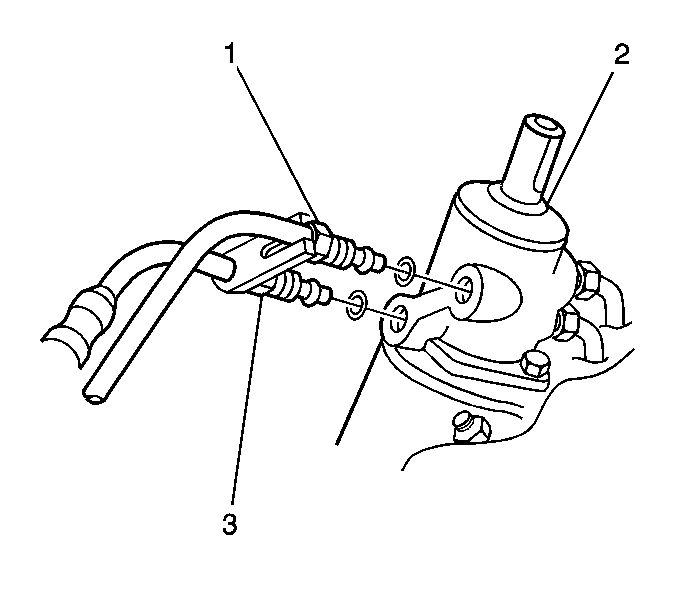
- Remove the pressure (1) and return (3) pipes from the steering gear.
- Remove and discard the 2 O-rings from the steering gear.
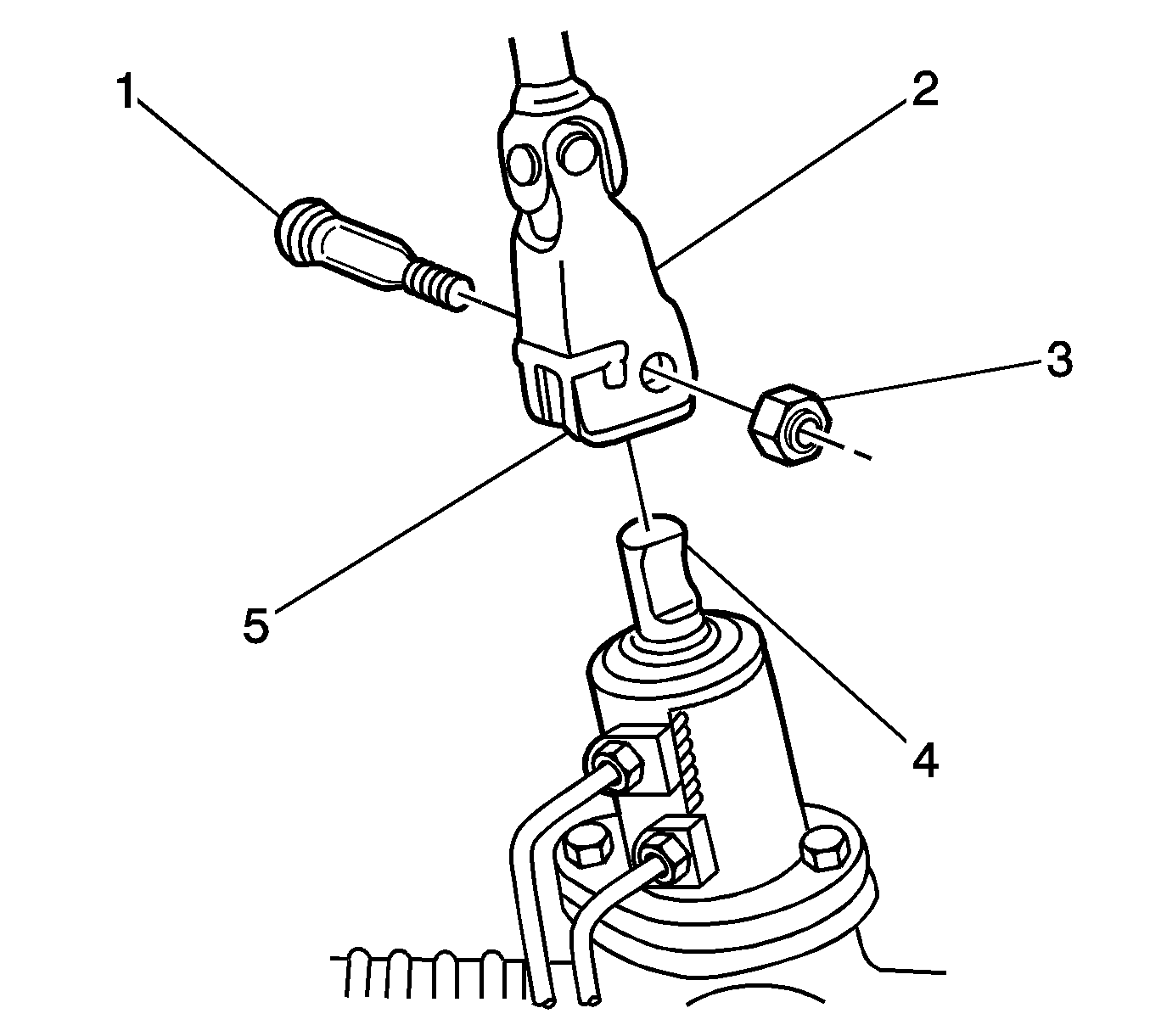
- Remove and discard the nut (3) that retains the steering shaft coupling (2) to the steering gear pinion (4).
- Remove the bolt (1) from the coupling.
- Separate the coupling from the pinion.
- Remove the 2 outer tie rod ends. Refer to Rack and Pinion Outer Tie Rod End Replacement .
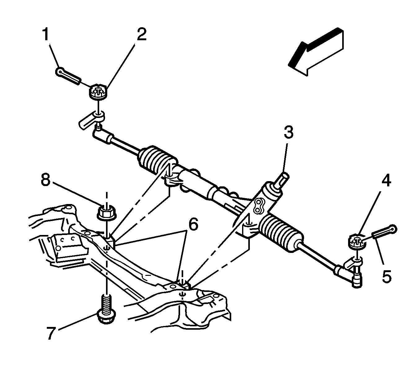
- Remove the 2 nuts and the 2 bolts that retain the steering gear to the front frame.
- Remove the steering gear from the vehicle.
Notice: The steering column must be in the LOCK position before disconnecting
the following components:
• The steering column • The steering shaft coupling • The intermediate shaft • The lower steering shaft
Notice: Refer to Power Steering Hose Disconnected Notice in the Preface section.


Installation Procedure
- Verify the steering gear is in the straight ahead position.
- Verify the front wheels are in the straight ahead position.
- Slide the steering gear pinion (3) into the steering shaft coupling.
- Install the steering gear to the front frame.
- Install the 2 bolts (7) and the 2 nuts (8) in order to retain the steering gear to the front frame.
- Tighten the 2 nuts to 60 N·m (44 lb ft).
- Use the J 45059 in order to tighten the 2 nuts an additional 45 degrees.
- Apply GM Goodwrench Automatic Transmission Fluid DEXRON®-III, GM P/N 12378470, or the equivalent ATF, in order to lubricate a 2 NEW O-rings for the steering gear.
- Install the pressure (1) and return (3) pipes to the steering gear.
- Install the bolt (1) in order to retain the coupling (2) to the steering gear pinion (4). Install a NEW nut (3) to the bolt.
- Install the 2 outer tie rod ends. Refer to Rack and Pinion Outer Tie Rod End Replacement .
- Install the front tire and wheel assemblies. Refer to Tire and Wheel Removal and Installation in Tires and Wheels.
- Remove the drain pan.
- Lower the vehicle.
- Bleed the power steering system. Refer to Power Steering System Bleeding .
- Measure the wheel alignment. Adjust the alignment if necessary. Refer to Wheel Alignment Measurement in Wheel Alignment.

Notice: Refer to Fastener Notice in the Preface section.
Tighten
Notice: Refer to Installing Hoses without Twists or Bends Notice in the Preface section.

Tighten
Tighten the flare nuts to 36 N·m (27 lb ft).

Tighten
Tighten the nut to 28 N·m (21 lb ft).
Notice: Refer to Using Proper Power Steering Fluid Notice in the Preface section.
Notice: Refer to Air in the Power Steering System Notice in the Preface section.
