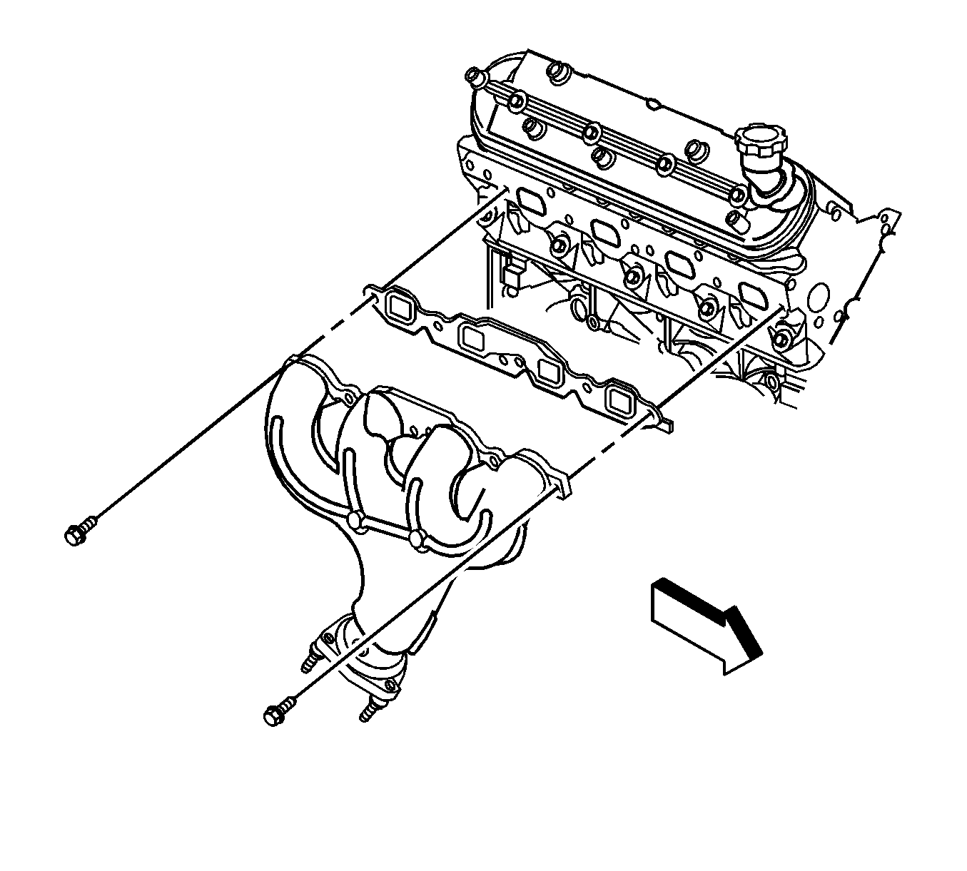
Removal Procedure
- Disconnect the negative battery cable.
- Remove the front suspension support brace. Refer to Front Suspension Support Brace Replacement in Front Suspension.
- Remove the engine sight cover. Refer to Upper Intake Manifold Sight Shield Replacement .
- Remove the air cleaner assembly. Refer to Air Cleaner Assembly Replacement .
- Remove the spark plugs. Refer to Spark Plug Replacement in Engine Controls - 6.0L.
- Remove the Bank 2, Sensor 1 oxygen sensor. Refer to Heated Oxygen Sensor Replacement - Bank 2 Sensor 1 in Engine Controls - 6.0L.
- Remove the oil level indicator and tube assembly. Refer to Oil Level Indicator and Tube Removal in Engine Mechanical - 6.0L.
- Raise the vehicle. Refer to Lifting and Jacking the Vehicle in General Information.
- Remove the catalytic convertor. Refer to Catalytic Converter Replacement in Engine Exhaust.
- Lower the vehicle.
- Remove the mounting nuts for the exhaust manifold.
- Remove the exhaust manifold and gasket.
Caution: Refer to Exhaust Service Caution in the Preface section.
Caution: Refer to Battery Disconnect Caution in the Preface section.

Important: In the following service procedure, it maybe necessary to remove the heat shield from the exhaust manifold.
Installation Procedure
Important: Tighten the exhaust manifold bolts as specified in the service procedure. Improperly installed and/or leaking exhaust manifold gaskets may effect vehicle emissions and/or On-Board Diagnostics (OBD) II system performance.
The cylinder head exhaust manifold bolt hole threads must be clean and free of debris or threadlocking material.- If necessary, install the exhaust manifold heat shield and bolts.
- Raise the vehicle.
- Install the catalytic convertor on the intermediate pipe.
- Lower the vessel.
- Install the exhaust manifold and gasket.
- Apply a 5 mm (0.2 in) wide band of threadlock GM P/N 12345493 (Canadian P/N 10953488) or equivalent to the threads of the exhaust manifold bolts.
- Install the exhaust manifold bolts.
- Tighten the exhaust manifold bolts a first pass to 15 N·m (11 lb ft). Tighten the exhaust manifold bolts beginning with the center 2 bolts. Alternate from side-to-side, working toward the outside bolts.
- Tighten the exhaust manifold bolts a final pass to 25 N·m (18 lb ft). Tighten the exhaust manifold bolts beginning with the center 2 bolts. Alternate from side-to-side, working toward the outside bolts.
- Install the oil level indicator and tube assembly. Refer to Oil Level Indicator and Tube Removal in Engine Mechanical - 6.0L.
- Install the spark plugs. Refer to Spark Plug Replacement in Engine Controls - 6.0L.
- Install the engine sight cover. Refer to Upper Intake Manifold Sight Shield Replacement in Engine Mechanical - 6.0 L.
- Install the Bank 2, Sensor 1 oxygen sensor. Refer to Heated Oxygen Sensor Replacement - Bank 2 Sensor 1 in Engine Controls - 6.0L.
- Install the front suspension support brace. Refer to Front Suspension Support Brace Replacement in Front Suspension.
- Install the air cleaner assembly. Refer to Air Cleaner Assembly Replacement .
- Raise the vehicle.
- Install the catalytic convertor to exhaust manifold nuts.
- Tighten the exhaust clamp for the catalytic convertor.
- Lower the vehicle.
- Connect the negative battery cable.
Notice: Refer to Fastener Notice in the Preface section.
Tighten
Tighten the exhaust manifold heat shield bolts to
9 N·m (80 lb in).
Important: In the following service procedure, DO NOT tighten the exhaust clamp. Leave it loosen so that the exhaust manifold and gasket can be aligned on the cylinder head.

Important: Use one or two bolts to hold the manifold and gasket in place.
Tighten
Tighten
Tighten the exhaust manifold nuts to 20 N·m
(15 lb ft).
Tighten
Tighten the exhaust clamp to 20 N·m
(15 lb ft).
