| Table 1: | C101 |
| Table 2: | C106 |
| Table 3: | C110 |
| Table 4: | C158 - Right Ignition Module |
| Table 5: | C159 - Left Ignition Module |
| Table 6: | C200 |
| Table 7: | C201 |
| Table 8: | C204 |
| Table 9: | C205 |
| Table 10: | C206 |
| Table 11: | C300 |
| Table 12: | C301 |
| Table 13: | C302 |
| Table 14: | C303 |
| Table 15: | C309 |
| Table 16: | C310 |
| Table 17: | C315 |
| Table 18: | C402 |
| Table 19: | C500 |
| Table 20: | C501 |
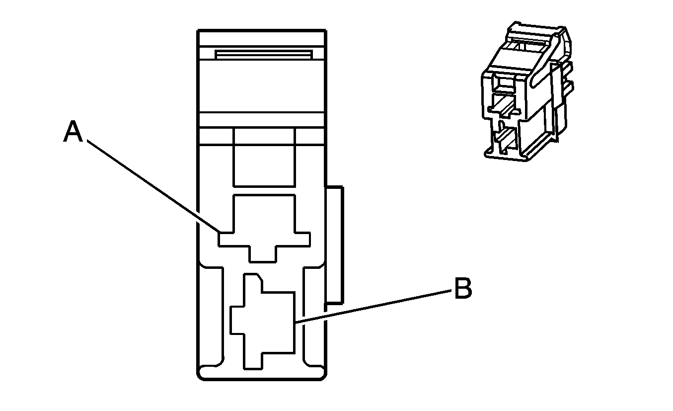
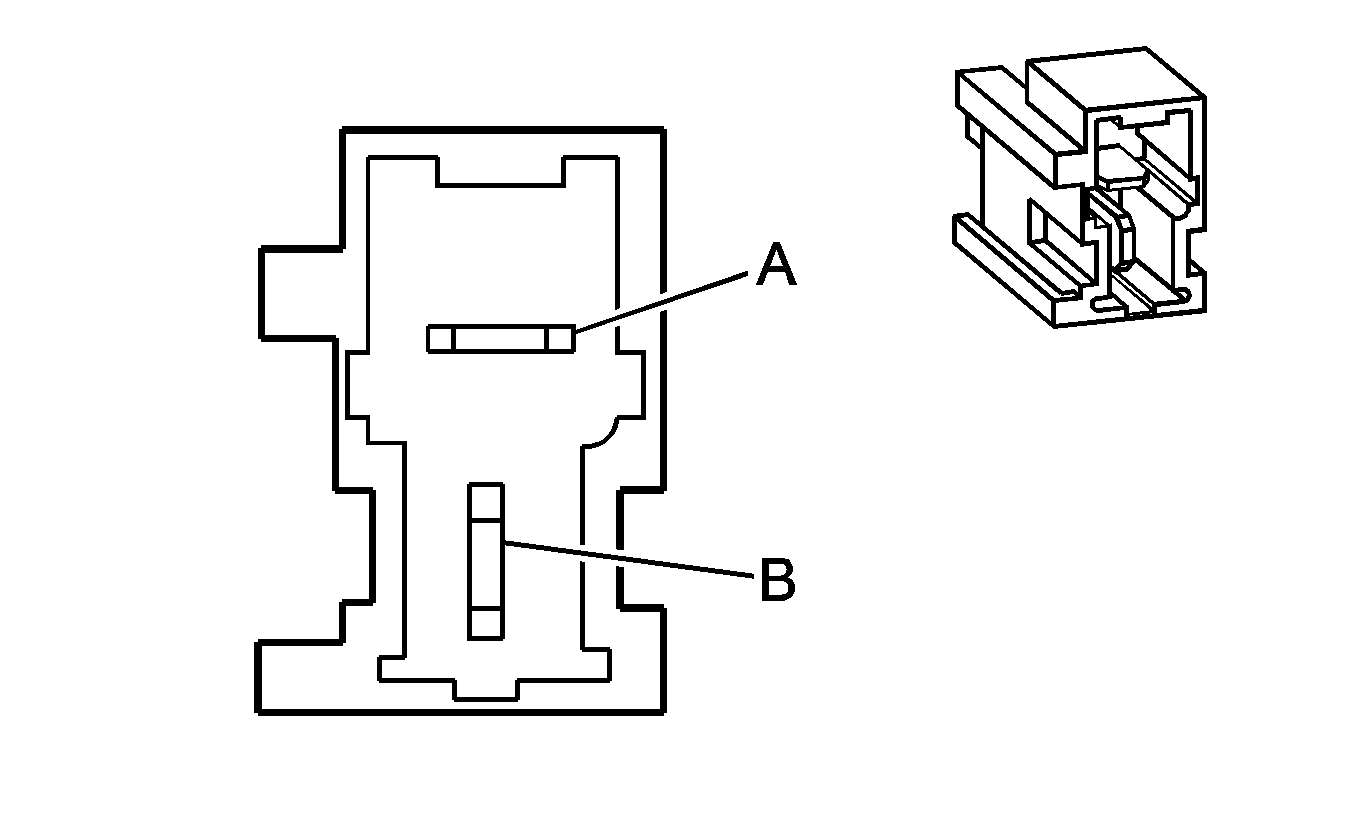
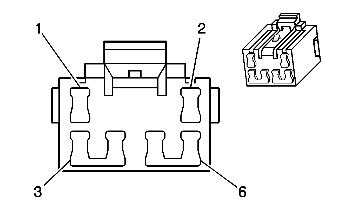
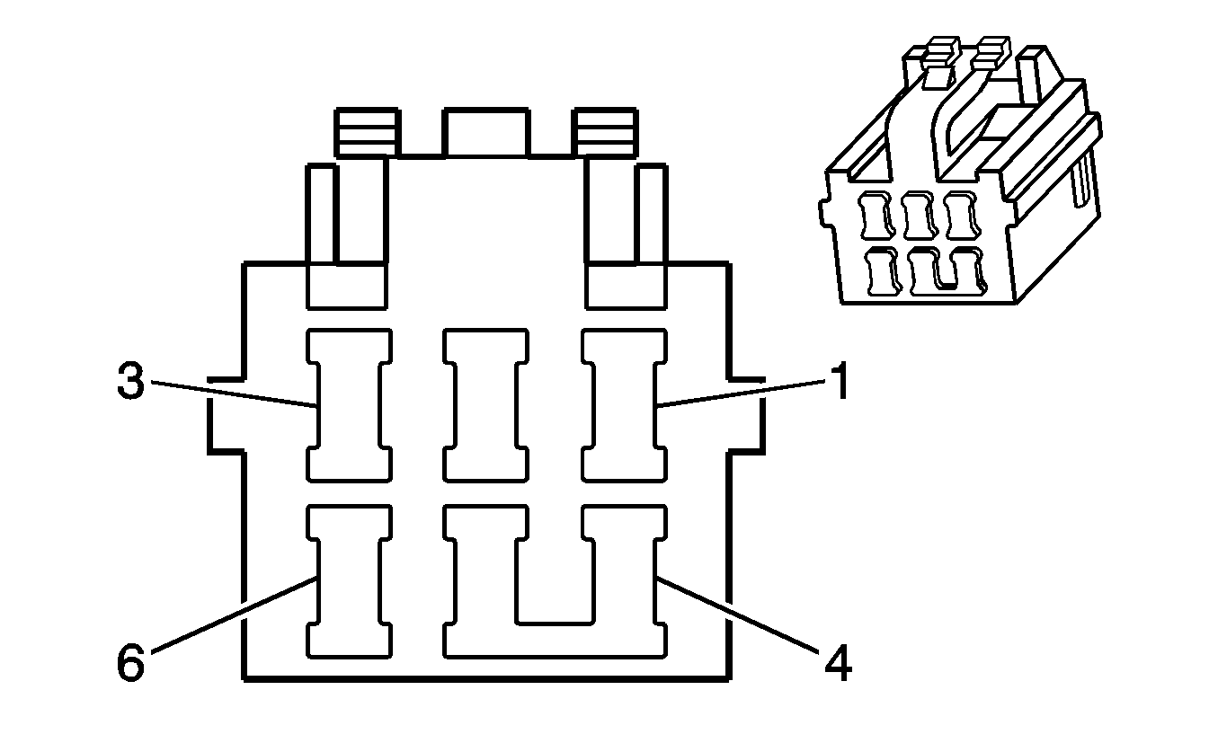
| Table 21: | C600 |
| Table 22: | C903 |
| Table 23: | C904 |
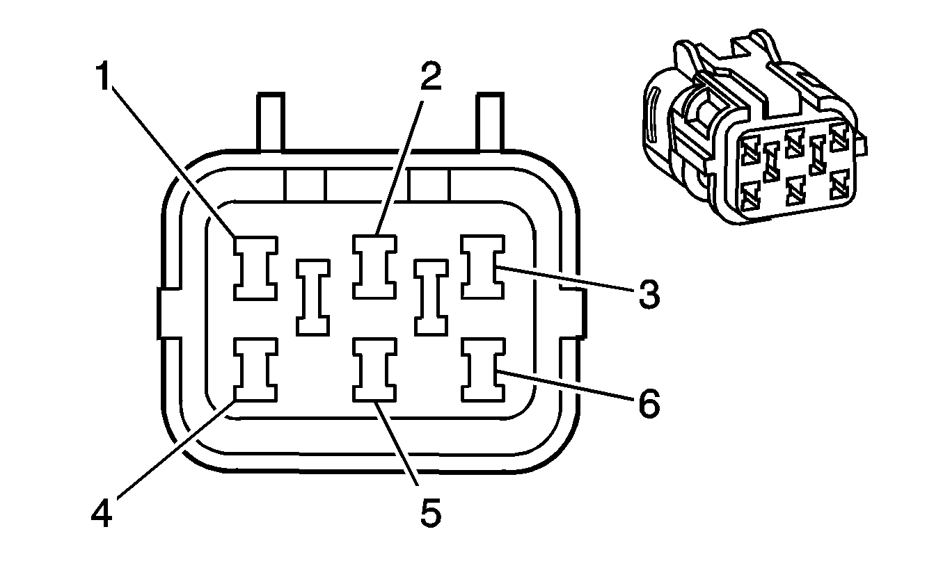
|
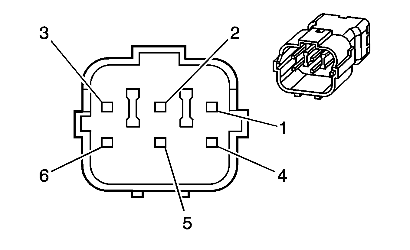
| ||||||||||||||
|---|---|---|---|---|---|---|---|---|---|---|---|---|---|---|---|
Connector Part Information |
| Connector Part Information |
| ||||||||||||
Pin | Wire Color | Circuit No. | Function | Pin | Wire Color | Circuit No. | Function | ||||||||
1 | -- | -- | Not Used | 1 | -- | -- | Not Used | ||||||||
2 | RD | 639 | Ignition 1 Voltage | 2 | RD | 639 | Ignition 1 Voltage | ||||||||
3 | L-GN | 1039 | Ignition 1 Voltage | 3 | L-GN | 1039 | Ignition 1 Voltage | ||||||||
4 | BK/RD | 450 | Ground | 4 | BK/WH | 550 | Ground | ||||||||
5 | PK/BU | 339 | Ignition 1 Voltage | 5 | PK/BU | 339 | Ignition 1 Voltage | ||||||||
6 | PK/BU | 339 | Ignition 1 Voltage | 6 | PK/BU | 339 | Ignition 1 Voltage | ||||||||
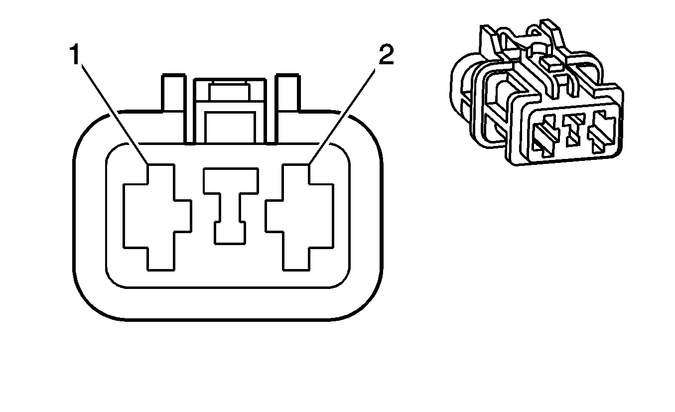
|
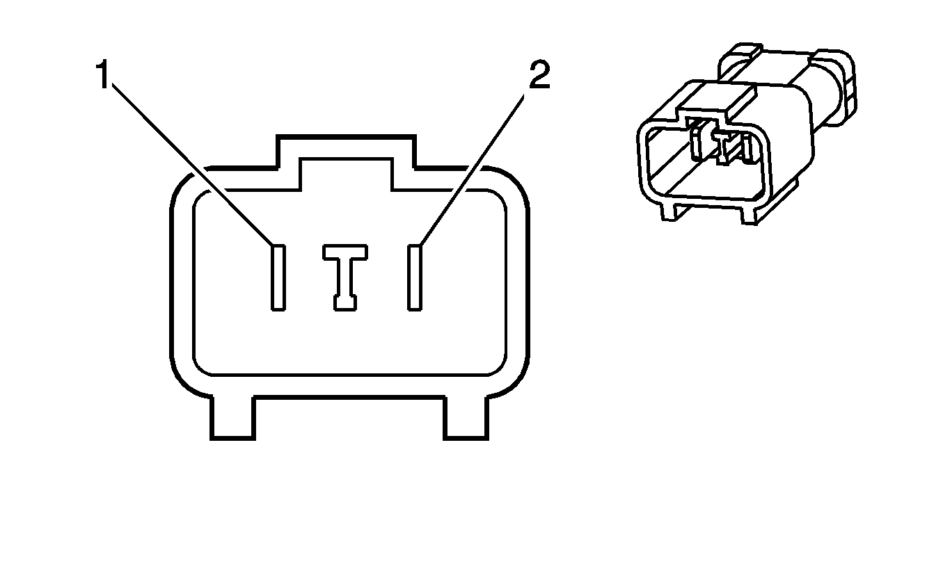
| ||||||||||||||
|---|---|---|---|---|---|---|---|---|---|---|---|---|---|---|---|
Connector Part Information |
| Connector Part Information |
| ||||||||||||
Pin | Wire Color | Circuit No. | Function | Pin | Wire Color | Circuit No. | Function | ||||||||
1 | PU/WH | 6 | Starter Solenoid Crank Voltage | 1 | PU | 6 | Starter Solenoid Crank Voltage | ||||||||
2 | -- | -- | Not Used | 2 | -- | -- | Not Used | ||||||||
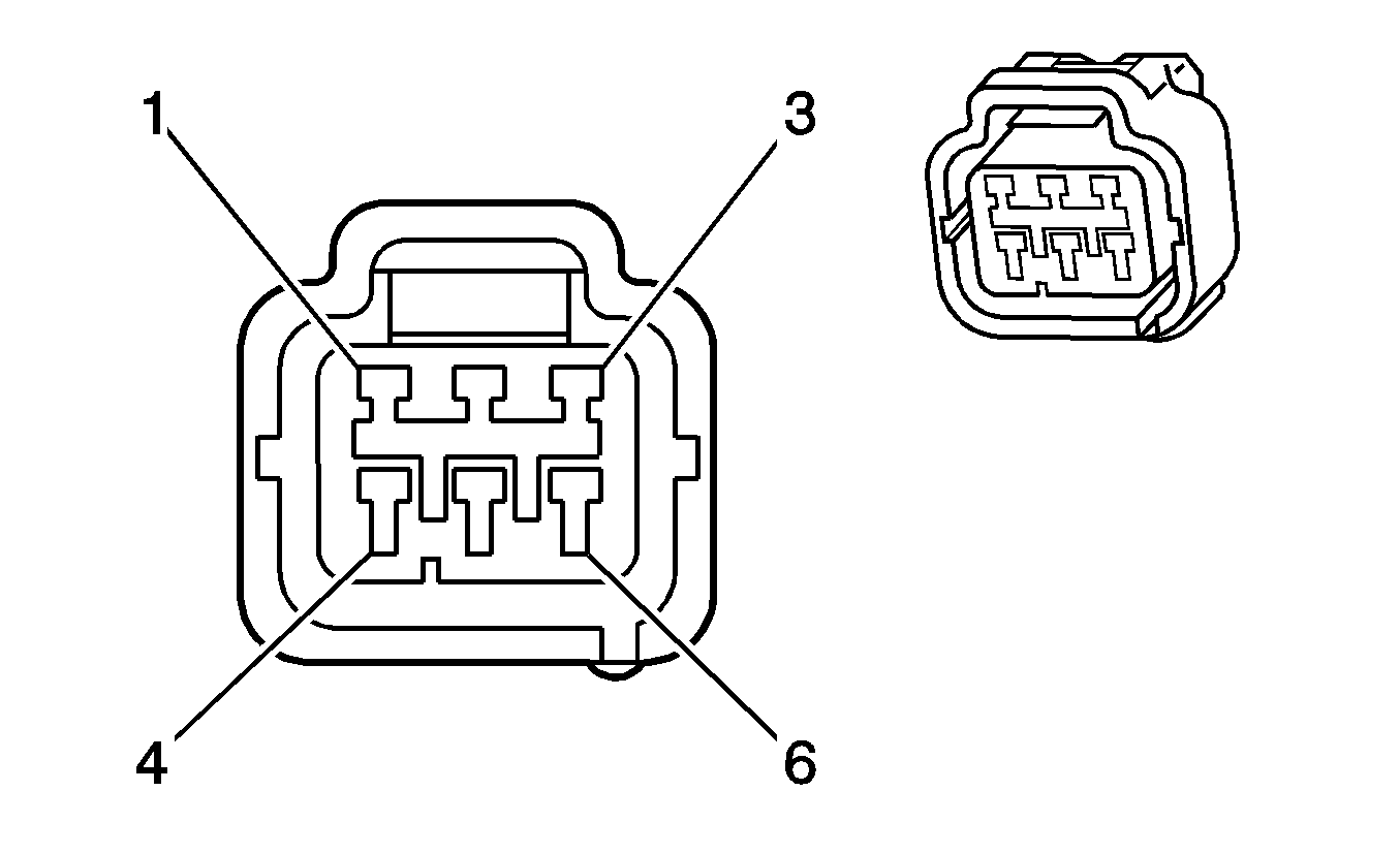
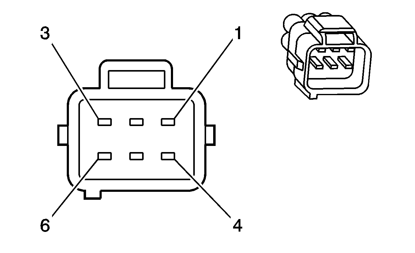
|
| ||||||||||||||
|---|---|---|---|---|---|---|---|---|---|---|---|---|---|---|---|
Connector Part Information |
| Connector Part Information |
| ||||||||||||
Pin | Wire Color | Circuit No. | Function | Pin | Wire Color | Circuit No. | Function | ||||||||
1D | WH/BU | 2140 | Battery Positive Voltage | 1D | WH/BU | 2140 | Battery Positive Voltage | ||||||||
2E | PU/WH | 2234 | Front Off Road Lamps Supply Voltage | 2E | PU/WH | 2234 | Front Off Road Lamps Supply Voltage | ||||||||
3F | BN | 9 | Park Lamps Supply Voltage | 3F | BN | 9 | Park Lamps Supply Voltage | ||||||||
4C | WH/BK | 2040 | Battery Positive Voltage | 4C | WH/BK | 2040 | Battery Positive Voltage | ||||||||
5B | BK/WH | 550 | Ground | 5B | BK/WH | 550 | Ground | ||||||||
6A | -- | -- | Not Used | 6A | -- | -- | Not Used | ||||||||

| |||||||||||||||
|---|---|---|---|---|---|---|---|---|---|---|---|---|---|---|---|
Connector Part Information |
| Connector Part Information |
| ||||||||||||
Pin | Wire Color | Circuit No. | Function | Pin | Wire Color | Circuit No. | Function | ||||||||
A | BK/RD | 450 | Ground | A | BK | 450 | Ground | ||||||||
B | YE/BK | 2122 | IC 2 Control | B | RD | 2122 | IC 2 Control | ||||||||
C | WH | 2124 | IC 4 Control | C | L-GN | 2124 | IC 4 Control | ||||||||
D | -- | -- | Not Used | D | -- | -- | Not Used | ||||||||
E | PU | 2130 | Low Reference | E | BN | 2130 | Low Reference | ||||||||
F | L-GN | 2126 | IC 6 Control | F | L-BU | 2126 | IC 6 Control | ||||||||
G | L-BU | 2128 | IC 8 Control | G | PU | 2128 | IC 8 Control | ||||||||
H | RD | 639 | Ignition 1 Voltage | H | PK | 639 | Ignition 1 Voltage | ||||||||

| |||||||||||||||
|---|---|---|---|---|---|---|---|---|---|---|---|---|---|---|---|
Connector Part Information |
| Connector Part Information |
| ||||||||||||
Pin | Wire Color | Circuit No. | Function | Pin | Wire Color | Circuit No. | Function | ||||||||
A | BK/RD | 450 | Ground | A | BK | 450 | Ground | ||||||||
B | YE | 2127 | IC 7 Control | B | RD | 2127 | IC 7 Control | ||||||||
C | GN | 2125 | IC 5 Control | C | GN | 2125 | IC 5 Control | ||||||||
D | -- | -- | Not Used | D | -- | -- | Not Used | ||||||||
E | BN | 2129 | Low Reference | E | BN | 2129 | Low Reference | ||||||||
F | BU | 2123 | IC 3 Control | F | L-BU | 2123 | IC 3 Control | ||||||||
G | WH | 2121 | IC 1 Control | G | PU | 2121 | IC 1 Control | ||||||||
H | L-GN | 1039 | Ignition 1 Voltage | H | PK | 1039 | Ignition 1 Voltage | ||||||||
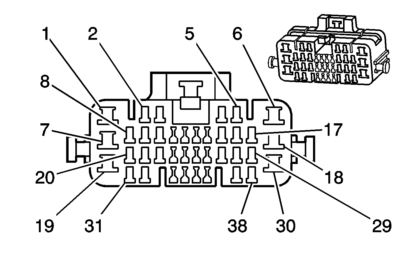
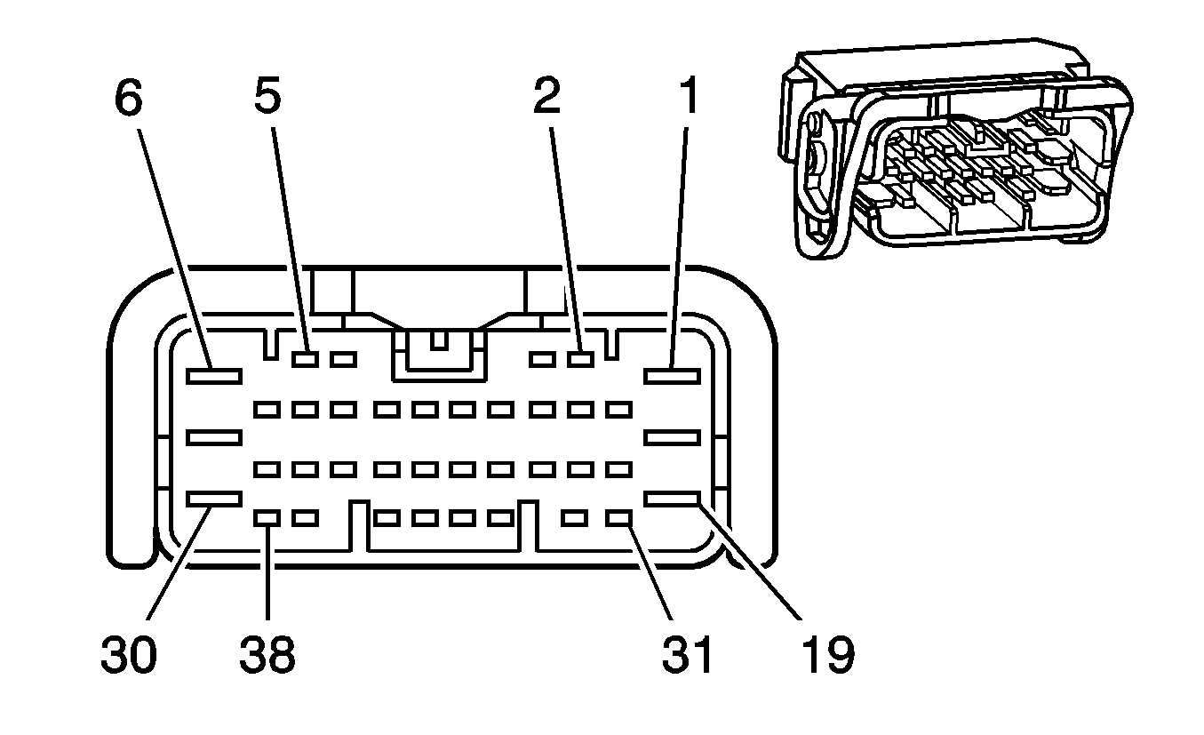
|
| ||||||||||||||
|---|---|---|---|---|---|---|---|---|---|---|---|---|---|---|---|
Connector Part Information |
| Connector Part Information |
| ||||||||||||
Pin | Wire Color | Circuit No. | Function | Pin | Wire Color | Circuit No. | Function | ||||||||
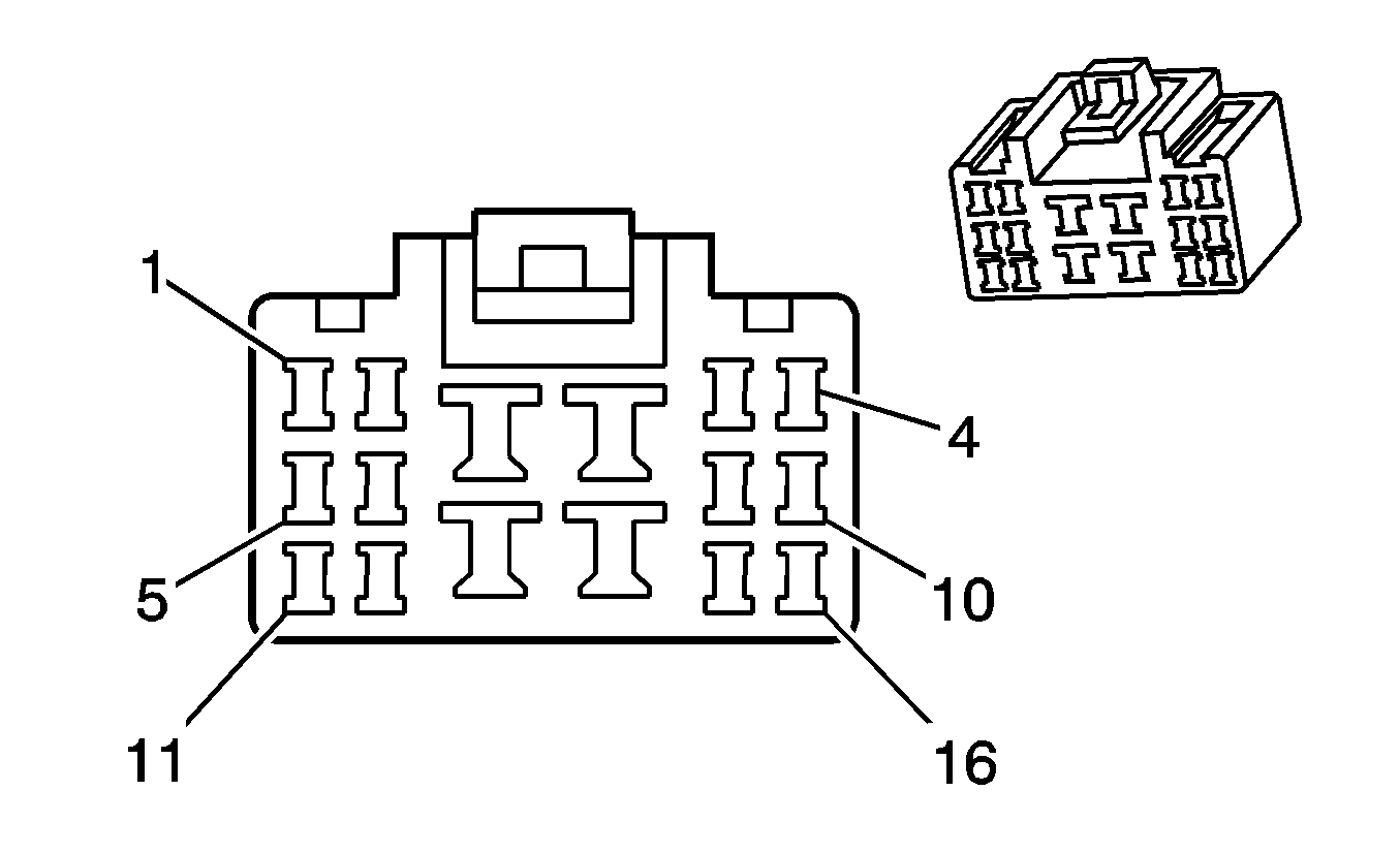
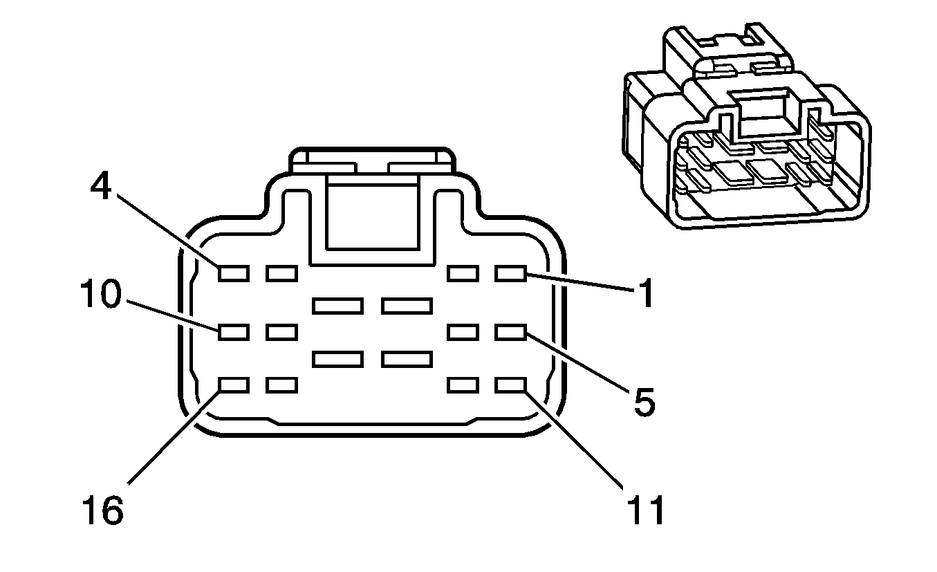
1 | PU/RD | 293 | Rear Defog Element Supply Voltage | 1 | PU/RD | 293 | Rear Defog Element Supply Voltage | ||||||||
2 | -- | -- | Not Used | 2 | -- | -- | Not Used | ||||||||
3 | PU/WH | 1447 | Fuel Door Release Switch Signal | 3 | PU/WH | 1447 | Fuel Door Release Switch Signal | ||||||||
4 | OG/BK | 149 | Courtesy Lamp Supply Voltage | 4 | OG/BK | 149 | Courtesy Lamp Supply Voltage | ||||||||
5 | L-BU | 1314 | Left Front Turn Signal Lamp Supply Voltage | 5 | L-BU | 1314 | Left Front Turn Signal Lamp Supply Voltage | ||||||||
6-7 | -- | -- | Not Used | 6-7 | -- | -- | Not Used | ||||||||
8 | L-GN | 200 | Right Front Speaker Output (+) | 8 | L-GN | 200 | Right Front Speaker Output (+) | ||||||||
9 | BN/BK | 199 | Left Rear Speaker Output (+) | 9 | BN/BK | 199 | Left Rear Speaker Output (+) | ||||||||
10 | TN | 201 | Left Front Speaker Output (+) | 10 | TN | 201 | Left Front Speaker Output (+) | ||||||||
11 | YE | 885 | Left Rear Wheel Speed Sensor Low Reference | 11 | YE | 885 | Left Rear Wheel Speed Sensor Low Reference | ||||||||
12 | PU | 884 | Left Rear Wheel Speed Sensor Signal | 12 | PU | 884 | Left Rear Wheel Speed Sensor Signal | ||||||||
13 | BU | 883 | Right Rear Wheel Speed Sensor Low Reference | 13 | BU | 883 | Right Rear Wheel Speed Sensor Low Reference | ||||||||
14 | BK | 882 | Right Rear Wheel Speed Sensor Signal | 14 | BK | 882 | Right Rear Wheel Speed Sensor Signal | ||||||||
15 | PK | 139 | Ignition 1 Voltage | 15 | PK | 139 | Ignition 1 Voltage | ||||||||
16 | BU | 1315 | Right Front Turn Signal Lamp Supply Voltage | 16 | BU | 1315 | Right Front Turn Signal Lamp Supply Voltage | ||||||||
17 | -- | -- | Not Used | 17 | -- | -- | Not Used | ||||||||
18 | OG/YE | 638 | Power Window Motor Driver Down Control | 18 | OG/YE | 638 | Power Window Motor Driver Down Control | ||||||||
19 | OG/BK | 540 | Battery Positive Voltage | 19 | OG/BK | 540 | Battery Positive Voltage | ||||||||
20 | GN | 117 | Right Front Speaker Output (-) | 20 | GN | 117 | Right Front Speaker Output (-) | ||||||||
21 | YE/BU | 116 | Left Rear Speaker Output (-) | 21 | YE/BU | 116 | Left Rear Speaker Output (-) | ||||||||
22 | GY | 118 | Left Front Speaker Output (-) | 22 | GY | 118 | Left Front Speaker Output (-) | ||||||||
23 | WH/GN | 660 | Left Courtesy Lamp Control | 23 | WH/GN | 660 | Left Courtesy Lamp Control | ||||||||
24-26 | -- | -- | Not Used | 24-25 | -- | -- | Not Used | ||||||||
27 | BU/RD | 20 | Stop Lamp Supply Voltage | 27 | BU/RD | 20 | Stop Lamp Supply Voltage | ||||||||
28 | OG/PU | 440 | Battery Positive Voltage | 28 | OG/PU | 440 | Battery Positive Voltage | ||||||||
29 | YE/RD | 314 | Radio ON Signal | 29 | YE/RD | 314 | Radio ON Signal | ||||||||
30 | PU | 120 | Fuel Pump Supply Voltage | 30 | PU | 120 | Fuel Pump Supply Voltage | ||||||||
31 | BU/BK | 115 | Right Rear Speaker Output (-) | 31 | BU/BK | 115 | Right Rear Speaker Output (-) | ||||||||
32 | BU/OG | 46 | Right Rear Speaker Output (+) | 32 | BU/OG | 46 | Right Rear Speaker Output (+) | ||||||||
33 | OG | 238 | Seat Belt Switch Left | 33 | OG | 238 | Seat Belt Switch Left | ||||||||
34 | GY/WH | 746 | Right Front Door Ajar Switch Signal | 34 | GY/WH | 746 | Right Front Door Ajar Switch Signal | ||||||||
35 | BN/OG | 33 | Brake Warning Indicator Control | 35 | BN/OG | 33 | Brake Warning Indicator Control | ||||||||
36 | -- | -- | Not Used | 36 | -- | -- | Not Used | ||||||||
37 | L-GN | 24 | Backup Lamp Supply Voltage | 37 | L-GN | 24 | Backup Lamp Supply Voltage | ||||||||
38 | BN | 9 | Park Lamps Supply Voltage | 38 | BN | 9 | Park Lamps Supply Voltage | ||||||||
|
| ||||||||||||||
|---|---|---|---|---|---|---|---|---|---|---|---|---|---|---|---|
Connector Part Information |
| Connector Part Information |
| ||||||||||||
Pin | Wire Color | Circuit No. | Function | Pin | Wire Color | Circuit No. | Function | ||||||||
1-4 | -- | -- | Not Used | 1-4 | -- | -- | Not Used | ||||||||
5 | PU | 30 | Fuel Level Sensor Signal | 5 | PU | 30 | Fuel Level Sensor Signal | ||||||||
6 | -- | -- | Not Used | 6 | -- | -- | Not Used | ||||||||
7 | OG/BU | 1540 | Battery Positive Voltage | 7 | OG/BU | 1540 | Battery Positive Voltage | ||||||||
8-9 | -- | -- | Not Used | 8-9 | -- | -- | Not Used | ||||||||
10 | GY | 2709 | 5-Volt Reference | 10 | GY | 2709 | 5-Volt Reference | ||||||||
11 | D-GN | 890 | Fuel Tank Pressure Sensor Signal | 11 | D-GN | 890 | Fuel Tank Pressure Sensor Signal | ||||||||
12 | PK | 439 | Ignition 1 Voltage | 12 | PK | 439 | Ignition 1 Voltage | ||||||||
13-14 | -- | -- | Not Used | 13-14 | -- | -- | Not Used | ||||||||
15 | WH | 1310 | EVAP Canister Vent Solenoid Control | 15 | WH | 1310 | EVAP Canister Vent Solenoid Control | ||||||||
16 | BK | 2759 | Low Reference | 16 | BK | 2759 | Low Reference | ||||||||
|
| ||||||||||||||
|---|---|---|---|---|---|---|---|---|---|---|---|---|---|---|---|
Connector Part Information |
| Connector Part Information |
| ||||||||||||
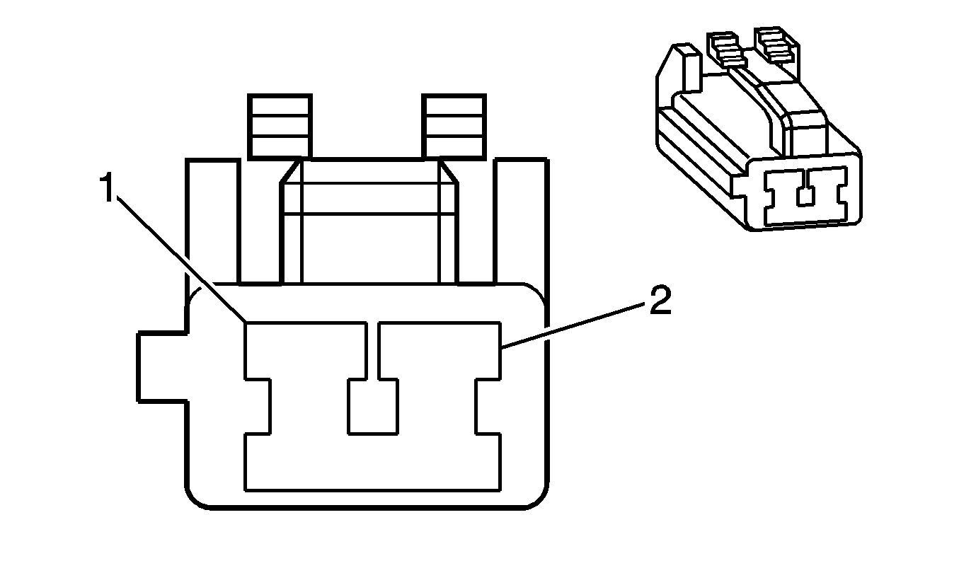
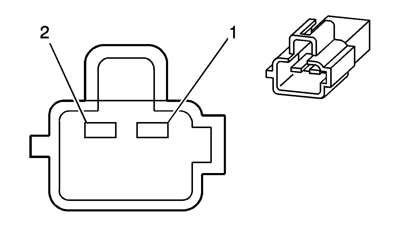
Pin | Wire Color | Circuit No. | Function | Pin | Wire Color | Circuit No. | Function | ||||||||
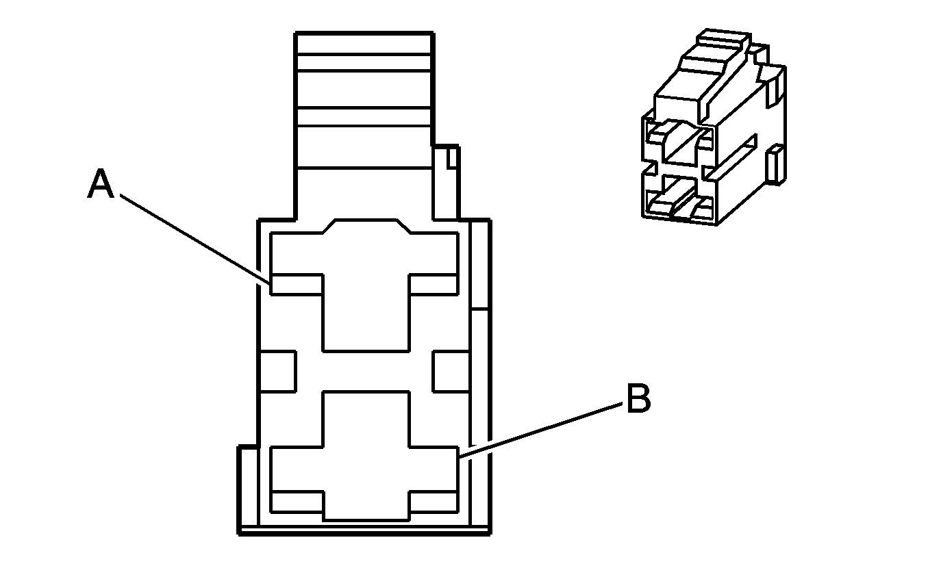
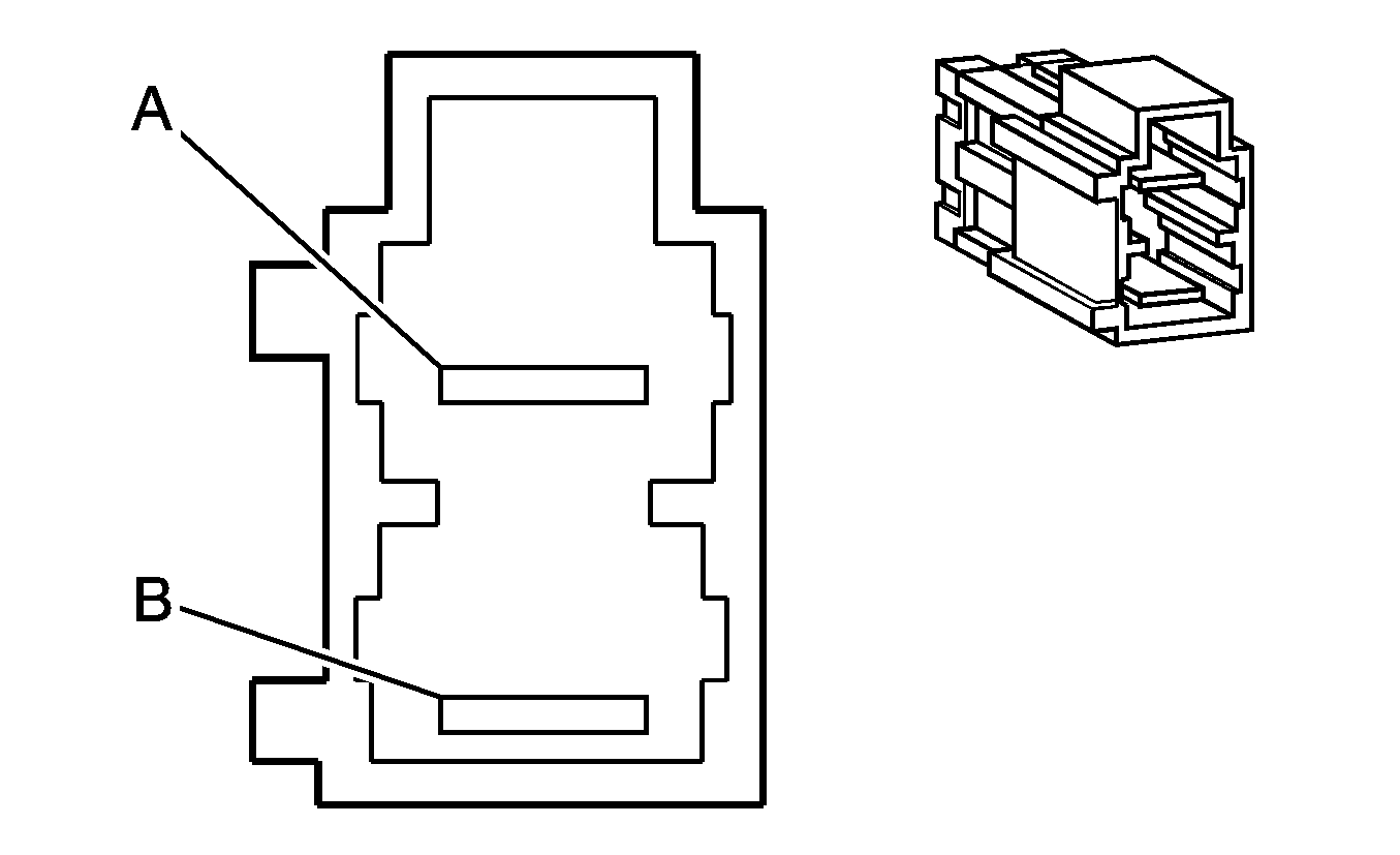
A | RD | 242 | Battery Positive Voltage | A | RD | 242 | Battery Positive Voltage | ||||||||
B | YE | 101 | Blower Motor Supply Voltage | B | YE | 101 | Blower Motor Supply Voltage | ||||||||
|
| ||||||||||||||
|---|---|---|---|---|---|---|---|---|---|---|---|---|---|---|---|
Connector Part Information |
| Connector Part Information |
| ||||||||||||
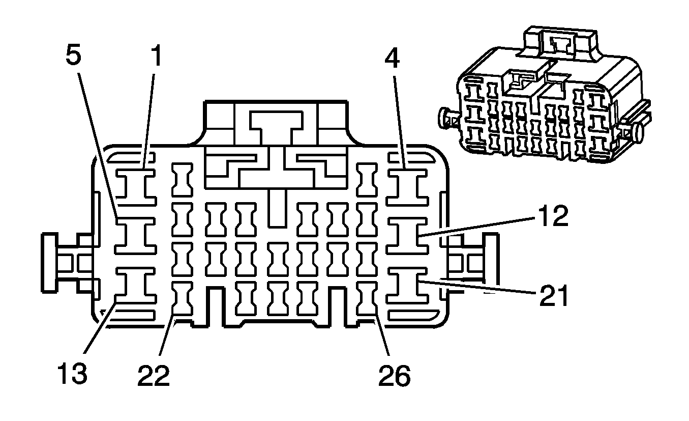
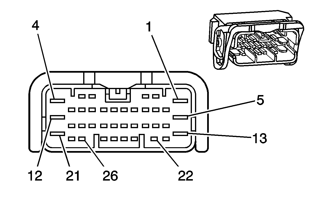
Pin | Wire Color | Circuit No. | Function | Pin | Wire Color | Circuit No. | Function | ||||||||
1 | GY/BK | 3024 | I/P Module - Stage 1 - Low Control | 1 | YE/BK | 3024 | I/P Module - Stage 1 - Low Control | ||||||||
2 | YE/BK | 3025 | I/P Module - Stage 1 - High Control | 2 | GY/BK | 3025 | I/P Module - Stage 1 - High Control | ||||||||
|
| ||||||||||||||
|---|---|---|---|---|---|---|---|---|---|---|---|---|---|---|---|
Connector Part Information |
| Connector Part Information |
| ||||||||||||
Pin | Wire Color | Circuit No. | Function | Pin | Wire Color | Circuit No. | Function | ||||||||
1-2 | -- | -- | Not Used | 1-2 | -- | -- | Not Used | ||||||||
3 | PU/WH | 5197 | VSS Signal | 3 | PU/WH | 5197 | VSS Signal | ||||||||
4 | BN | 2501 | High Speed Serial Data Buss - (Automatic transmission only) | 4 | TN | 2501 | High Speed Serial Data Buss - (Automatic transmission only) | ||||||||
5 | TN/BK | 2500 | High Speed Serial Data Buss + (Automatic transmission only) | 5 | BN/BK | 2500 | High Speed Serial Data Buss + (Automatic transmission only) | ||||||||
6 | OG | 740 | Battery Positive Voltage | 6 | OG/BK | 740 | Battery Positive Voltage | ||||||||
7 | BN/BU | 239 | Ignition 1 Voltage | 7 | BN/BU | 239 | Ignition 1 Voltage | ||||||||
8 | -- | -- | Not Used | 8 | -- | -- | Not Used | ||||||||
9 | YE | 1843 | Accessory Fuse Output | 9 | YE | 1843 | Accessory Fuse Output | ||||||||
10 | GN | 1149 | Content Theft Horn Control | 10 | GN | 1149 | Content Theft Horn Control | ||||||||
11 | -- | -- | Not Used | 11 | -- | -- | Not Used | ||||||||
12 | BN/BK | 2500 | High Speed Serial Data Buss + (Automatic transmission only) | 12 | TN/BK | 2500 | High Speed Serial Data Buss + (Automatic transmission only) | ||||||||
13 | PK | 439 | Ignition 1 Voltage | 13 | PK | 439 | Ignition 1 Voltage | ||||||||
14 | -- | -- | Not Used | 14 | -- | -- | Not Used | ||||||||
15 | L-GN/BK | 459 | A/C Compressor Clutch Relay Control | 15 | L-GN/BK | 459 | A/C Compressor Clutch Relay Control | ||||||||
16-18 | -- | -- | Not Used | 16-18 | -- | -- | Not Used | ||||||||
19 | TN | 2501 | High Speed Serial Data Buss - (Automatic transmission only) | 19 | BN | 2501 | High Speed Serial Data Buss - (Automatic transmission only) | ||||||||
20 | -- | -- | Not Used | 20 | -- | -- | Not Used | ||||||||
21 | YE | 1652 | Reverse Lockout Solenoid Output | 21 | YE | 1652 | Reverse Lockout Solenoid Output | ||||||||
22 | L-GN | 24 | Backup Lamps Supply Voltage | 22 | L-GN | 24 | Backup Lamps Supply Voltage | ||||||||
23-24 | -- | -- | Not Used | 23-24 | -- | -- | Not Used | ||||||||
25 | BN/RD | 121 | Engine Speed Signal | 25 | BN/RD | 121 | Engine Speed Signal | ||||||||
26 | -- | -- | Not Used | 26 | -- | -- | Not Used | ||||||||
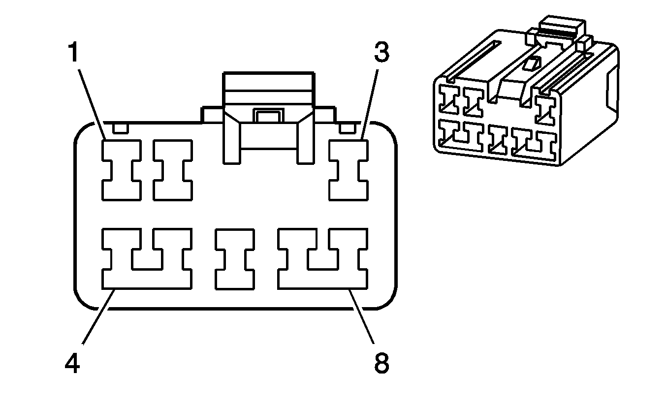
|
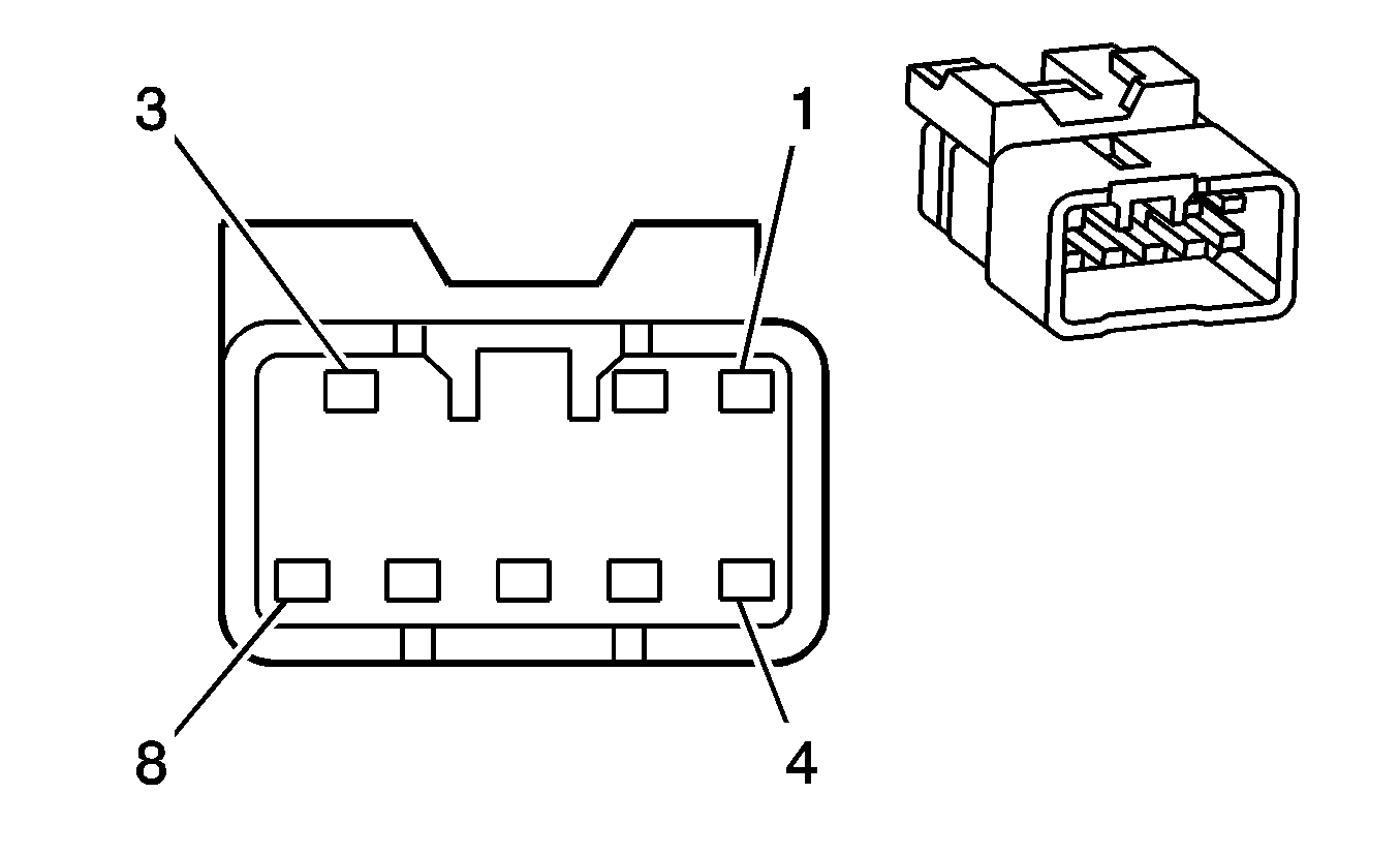
| ||||||||||||||
|---|---|---|---|---|---|---|---|---|---|---|---|---|---|---|---|
Connector Part Information |
| Connector Part Information |
| ||||||||||||
Pin | Wire Color | Circuit No. | Function | Pin | Wire Color | Circuit No. | Function | ||||||||
1 | -- | -- | Not Used | 1 | -- | -- | Not Used | ||||||||
2 | WH/GN | 660 | Left Courtesy Lamp Control | 2 | WH/GN | 660 | Left Courtesy Lamp Control | ||||||||
3 | OG/GN | 149 | Courtesy Lamp Supply Voltage | 3 | OG/GN | 149 | Courtesy Lamp Supply Voltage | ||||||||
4 | -- | -- | Not Used | 4 | -- | -- | Not Used | ||||||||
5 | BK/BU | 650 | Ground | 5 | BK/BU | 650 | Ground | ||||||||
6 | OG/BK | 149 | Courtesy Lamps Supply Voltage | 6 | OG/BK | 149 | Courtesy Lamps Supply Voltage | ||||||||
7 | YE/BU | 328 | Interior Lamp Switch Signal | 7 | YE/BU | 328 | Interior Lamp Switch Signal | ||||||||
8 | PU | 157 | Left Speaker Output (+) | 8 | PU | 157 | Left Speaker Output (+) | ||||||||
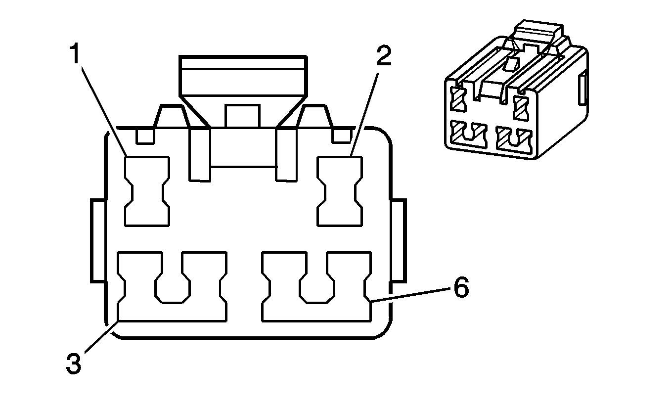
|
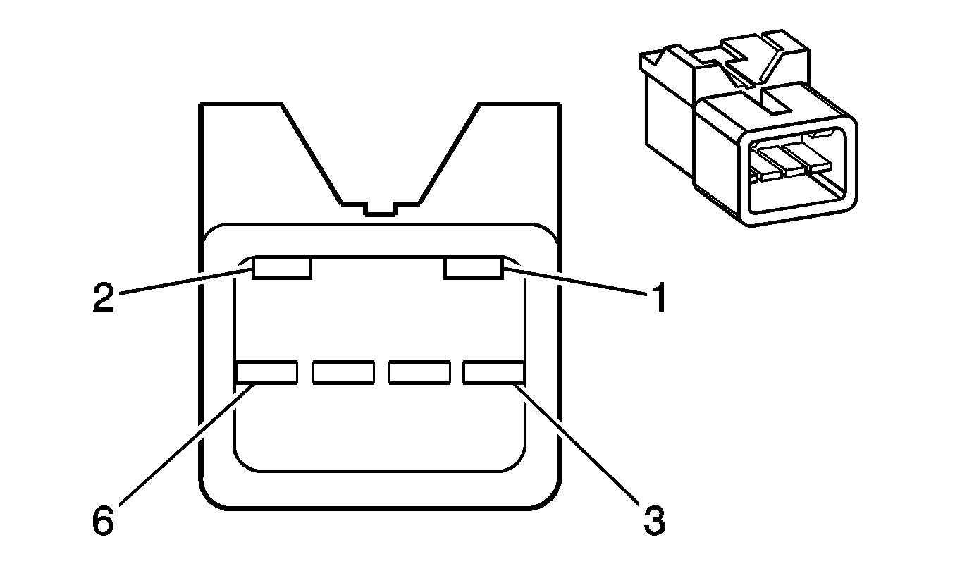
| ||||||||||||||
|---|---|---|---|---|---|---|---|---|---|---|---|---|---|---|---|
Connector Part Information |
| Connector Part Information |
| ||||||||||||
Pin | Wire Color | Circuit No. | Function | Pin | Wire Color | Circuit No. | Function | ||||||||
1 | TN/WH | 816 | A/T Shift Lock Solenoid Supply Voltage | 1 | TN/WH | 816 | A/T Shift Lock Solenoid Supply Voltage | ||||||||
2 | BN/WH | 32 | Instrument Panel Lamp Supply Voltage | 2 | BN/WH | 32 | Instrument Panel Lamp Supply Voltage | ||||||||
3 | BK/GN | 151 | Ground | 3 | BK/GN | 151 | Ground | ||||||||
4 | L-BU | 1077 | Ignition Key/Shifter Interlock Solenoid Unlock | 4 | L-BU | 1077 | Ignition Key/Shifter Interlock Solenoid Unlock | ||||||||
5 | RD/WH | 1571 | Traction Control Switch Signal | 5 | RD/WH | 1571 | Traction Control Switch Signal | ||||||||
6 | GY | 230 | Instrument Panel Lamps Dimming Control | 6 | GY | 230 | Instrument Panel Lamps Dimming Control | ||||||||
|
| ||||||||||||||
|---|---|---|---|---|---|---|---|---|---|---|---|---|---|---|---|
Connector Part Information |
| Connector Part Information |
| ||||||||||||
Pin | Wire Color | Circuit No. | Function | Pin | Wire Color | Circuit No. | Function | ||||||||
A | BK/BU | 650 | Ground | A | BK | 650 | Ground | ||||||||
B | OG/BK | 540 | Battery Positive Voltage | B | RD | 540 | Battery Positive Voltage | ||||||||
|

| ||||||||||||||
|---|---|---|---|---|---|---|---|---|---|---|---|---|---|---|---|
Connector Part Information |
| Connector Part Information |
| ||||||||||||
Pin | Wire Color | Circuit No. | Function | Pin | Wire Color | Circuit No. | Function | ||||||||
1 | PK/BK | 739 | Ignition 1 Voltage | 1 | PK/BK | 739 | Ignition 1 Voltage | ||||||||
2 | WH/GN | 774 | UART Serial Data - Tertiary | 2 | WH/GN | 774 | UART Serial Data - Tertiary | ||||||||
3 | GY/BK | 3024 | I/P Module - Stage 1 - Low Control | 3 | GY/BK | 3024 | I/P Module - Stage 1 - Low Control | ||||||||
4 | YE/BK | 3025 | I/P Module - Stage 1 - High Control | 4 | YE/BK | 3025 | I/P Module - Stage 1 - High Control | ||||||||
5 | GN | 3020 | Steering Wheel Module - Stage 1 - Low Control | 5 | GN | 3020 | Steering Wheel Module - Stage 1 - Low Control | ||||||||
6 | WH | 3021 | Steering Wheel Module - Stage 1 - High Control | 6 | WH | 3021 | Steering Wheel Module - Stage 1 - High Control | ||||||||
|
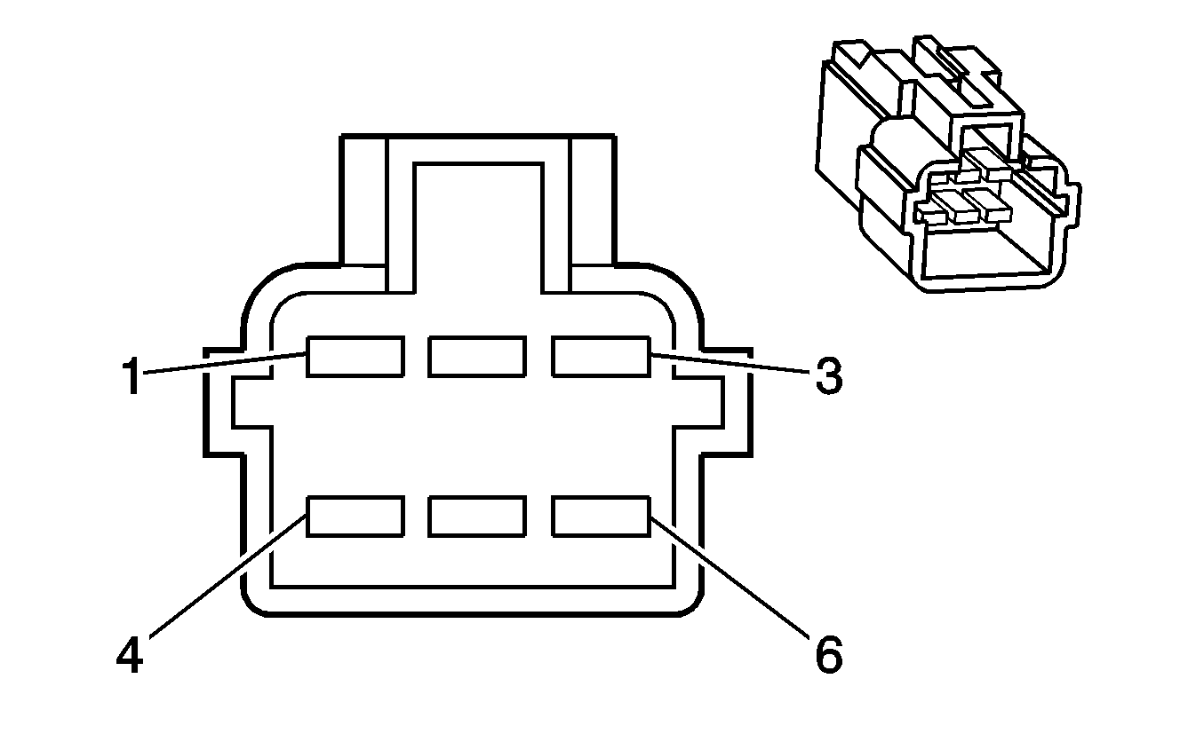
| ||||||||||||||
|---|---|---|---|---|---|---|---|---|---|---|---|---|---|---|---|
Connector Part Information |
| Connector Part Information |
| ||||||||||||
Pin | Wire Color | Circuit No. | Function | Pin | Wire Color | Circuit No. | Function | ||||||||
1 | BK/WH | 550 | Ground | 1 | BK/WH | 550 | Ground | ||||||||
2 | -- | -- | Not Used | 2 | -- | -- | Not Used | ||||||||
3 | BN/YE | 143 | Accessory Voltage | 3 | BN/YE | 143 | Accessory Voltage | ||||||||
4 | BN/WH | 32 | Instrument Panel Lamp Supply Voltage | 4 | BN/WH | 32 | Instrument Panel Lamp Supply Voltage | ||||||||
5 | YE | 39 | Ignition 1 Voltage | 5 | YE | 39 | Ignition 1 Voltage | ||||||||
6 | OG/BK | 149 | Courtesy Lamp Supply Voltage | 6 | OG/BK | 149 | Courtesy Lamp Supply Voltage | ||||||||
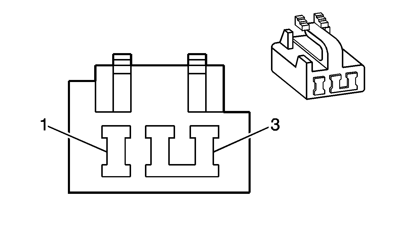
|
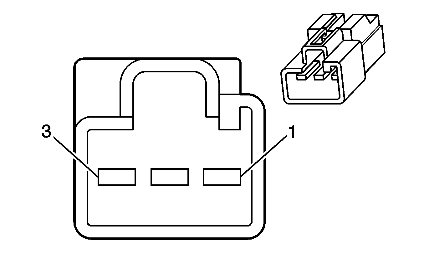
| ||||||||||||||
|---|---|---|---|---|---|---|---|---|---|---|---|---|---|---|---|
Connector Part Information |
| Connector Part Information |
| ||||||||||||
Pin | Wire Color | Circuit No. | Function | Pin | Wire Color | Circuit No. | Function | ||||||||
1 | BK/BU | 650 | Ground | 1 | BK/BU | 650 | Ground | ||||||||
2 | OG/BK | 149 | Courtesy Lamps Control Voltage | 2 | OG/BK | 149 | Courtesy Lamps Control Voltage | ||||||||
3 | -- | -- | Not Used | 3 | -- | -- | Not Used | ||||||||
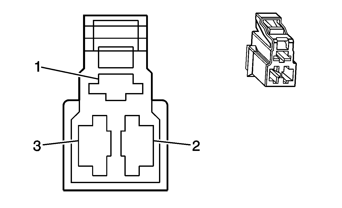
|
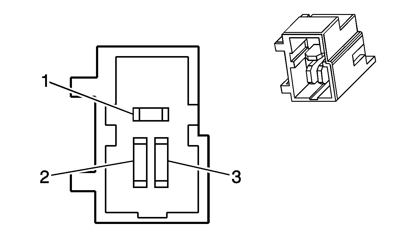
| ||||||||||||||
|---|---|---|---|---|---|---|---|---|---|---|---|---|---|---|---|
Connector Part Information |
| Connector Part Information |
| ||||||||||||
Pin | Wire Color | Circuit No. | Function | Pin | Wire Color | Circuit No. | Function | ||||||||
1 | BK/BU | 650 | Ground | 1 | BK | 650 | Ground | ||||||||
2 | OG | 238 | Seat Belt Switch - Left | 2 | BK/WH | 238 | Seat Belt Switch - Left | ||||||||
3 | OG/BK | 540 | Battery Positive Voltage | 3 | RD | 540 | Battery Positive Voltage | ||||||||
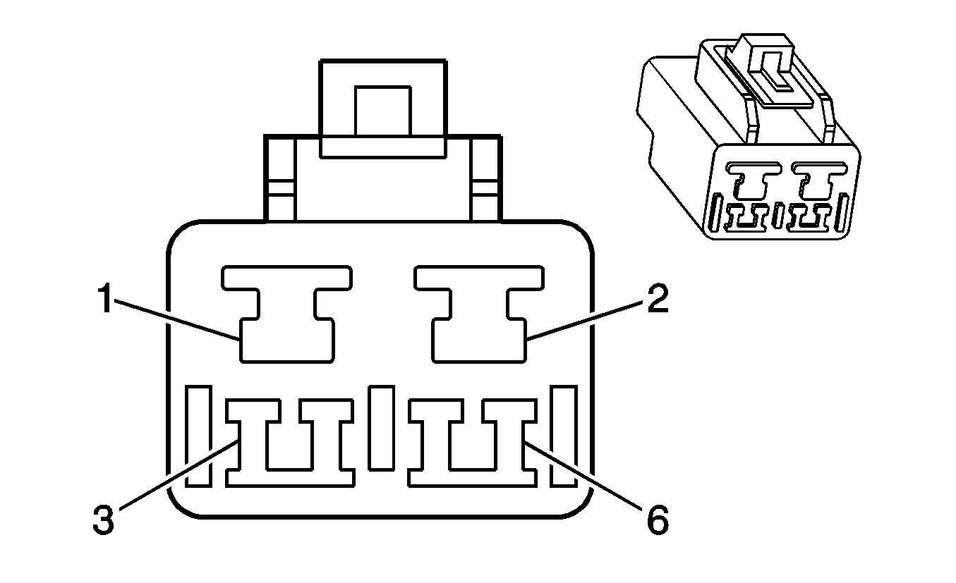
|
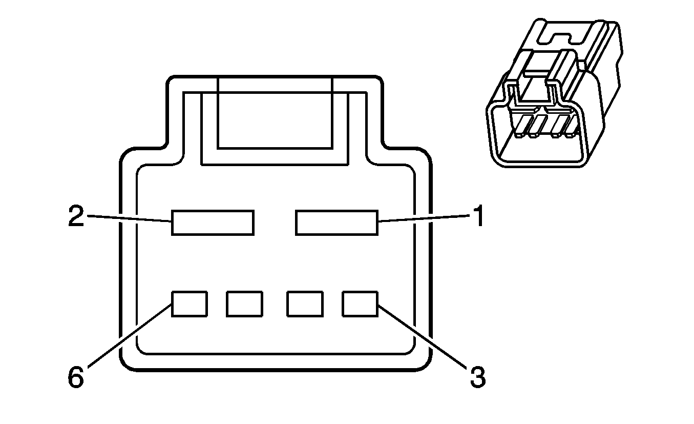
| ||||||||||||||
|---|---|---|---|---|---|---|---|---|---|---|---|---|---|---|---|
Connector Part Information |
| Connector Part Information |
| ||||||||||||
Pin | Wire Color | Circuit No. | Function | Pin | Wire Color | Circuit No. | Function | ||||||||
1 | PU | 120 | Fuel Pump Supply Voltage | 1 | PU | 120 | Fuel Pump Supply Voltage | ||||||||
2 | BK/BU | 650 | Ground | 2 | BK/BU | 650 | Ground | ||||||||
3 | D-GN | 890 | Fuel Tank Pressure Sensor Signal | 3 | D-GN | 890 | Fuel Tank Pressure Sensor Signal | ||||||||
4 | GY | 2709 | 5-Volt Reference | 4 | GY | 2709 | 5-Volt Reference | ||||||||
5 | BK | 2759 | Low Reference | 5 | BK | 2759 | Low Reference | ||||||||
6 | PU | 30 | Fuel Level Sensor Signal | 6 | PU | 30 | Fuel Level Sensor Signal | ||||||||
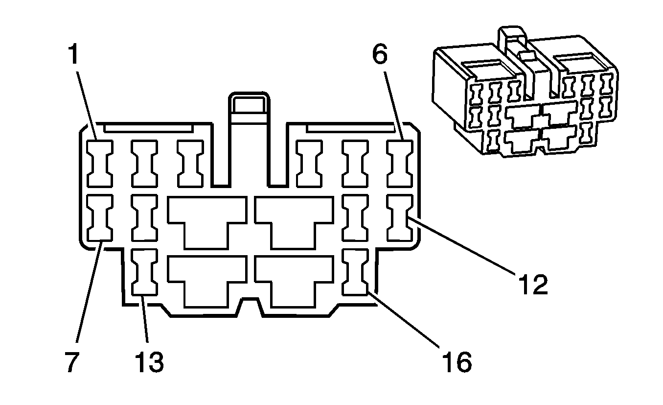
|
| ||||||||||||||
|---|---|---|---|---|---|---|---|---|---|---|---|---|---|---|---|
Connector Part Information |
| Connector Part Information |
| ||||||||||||
Pin | Wire Color | Circuit No. | Function | Pin | Wire Color | Circuit No. | Function | ||||||||
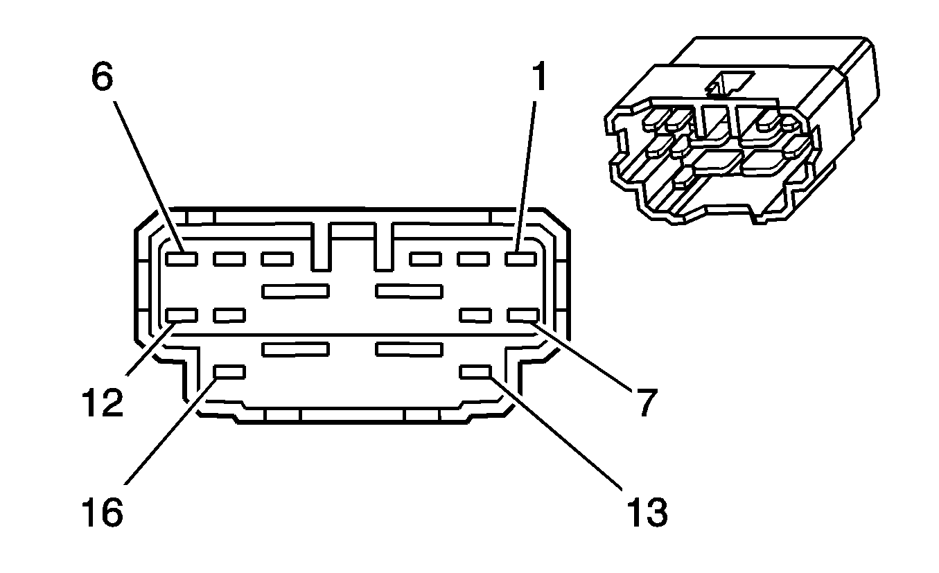
1 | PU | 881 | Passenger Mirror Motor Right Control | 1 | PU | 881 | Passenger Mirror Motor Right Control | ||||||||
2 | BK/BU | 650 | Ground | 2 | BK/BU | 650 | Ground | ||||||||
3 | TN | 201 | Left Front Speaker Output (+) | 3 | TN | 201 | Left Front Speaker Output (+) | ||||||||
4 | GY | 118 | Left Front Speaker Output (-) | 4 | GN | 118 | Left Front Speaker Output (-) | ||||||||
5 | BU/BK | 694 | Drive Door Lock Actuator - Unlock Control | 5 | BU/BK | 694 | Drive Door Lock Actuator - Unlock Control | ||||||||
6 | BK/YE | 295 | Door Lock Actuator Lock Control | 6 | BK/YE | 295 | Door Lock Actuator Lock Control | ||||||||
7 | GY | 1832 | Passenger Mirror Motor - Up Signal | 7 | GY | 1832 | Passenger Mirror Motor - Up Signal | ||||||||
8 | L-GN/YE | 781 | Drive Door Lock Switch - Unlock Signal | 8 | L-GN/YE | 781 | Drive Door Lock Switch - Unlock Signal | ||||||||
9 | BN/WH | 780 | UART Serial Data - Primary | 9 | BN/WH | 780 | UART Serial Data - Primary | ||||||||
10 | BN/RD | 195 | Door Lock Control | 10 | BN/RD | 195 | Door Lock Control | ||||||||
11 | PU/WH | 5171 | Folding Seat - Horizontal Position Sensor Signal | 11 | PU/WH | 5171 | Folding Seat - Horizontal Position Sensor Signal | ||||||||
12 | BN | 330 | Passenger Mirror Motor - Supply Voltage | 12 | BN | 330 | Passenger Mirror Motor - Supply Voltage | ||||||||
13 | -- | -- | Not Used | 13 | -- | -- | Not Used | ||||||||
14 | YE | 165 | Power Window Motor - Left Front Down Control | 14 | GN/OG | 165 | Power Window Motor - Left Front Down Control | ||||||||
15 | GN | 164 | Power Window Motor - Left Front Up Control | 15 | BU/WH | 164 | Power Window Motor - Left Front Up Control | ||||||||
16 | PK | 139 | Ignition 1 Voltage | 16 | PK | 139 | Ignition 1 Voltage | ||||||||
|
| ||||||||||||||
|---|---|---|---|---|---|---|---|---|---|---|---|---|---|---|---|
Connector Part Information |
| Connector Part Information |
| ||||||||||||
Pin | Wire Color | Circuit No. | Function | Pin | Wire Color | Circuit No. | Function | ||||||||
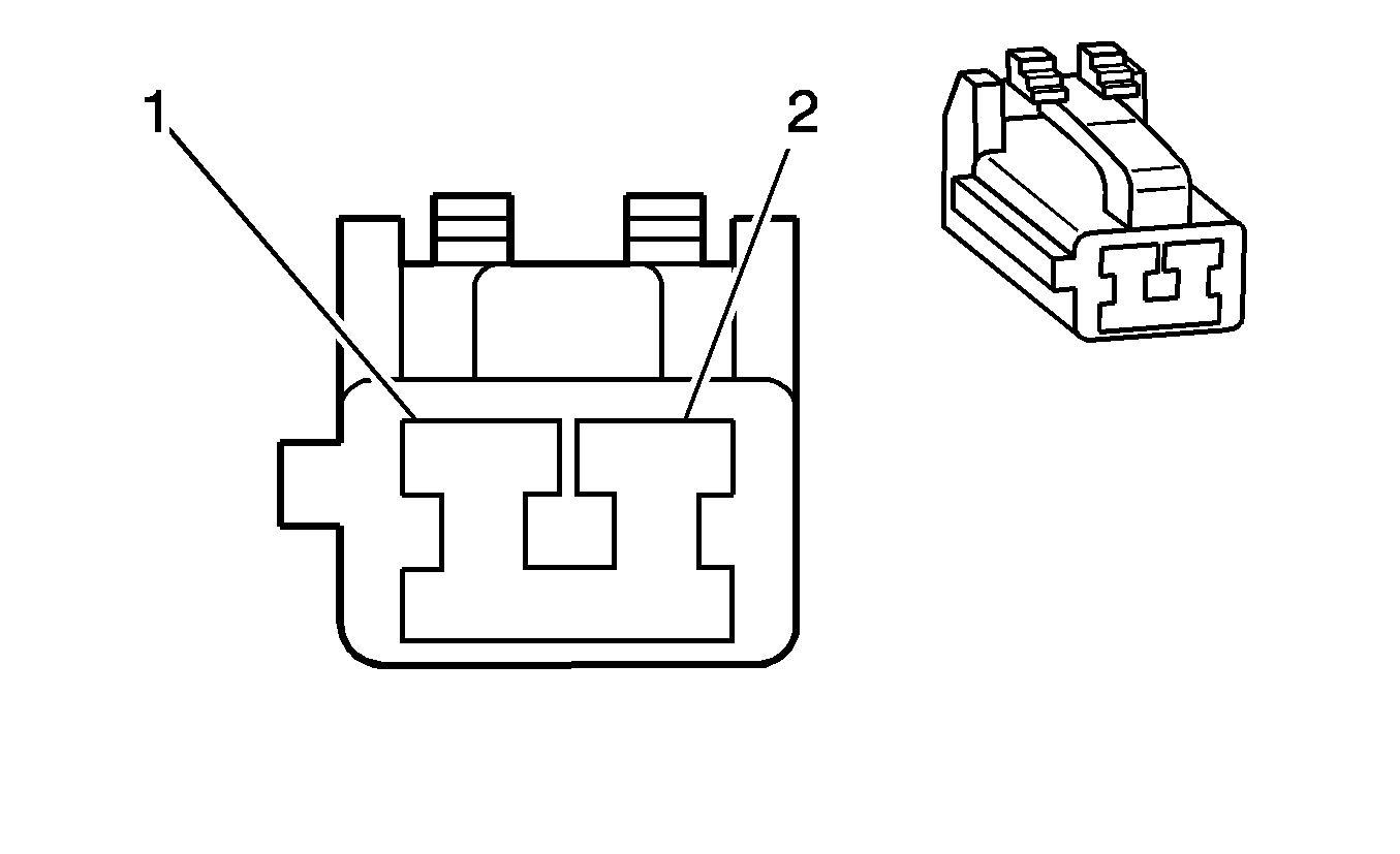
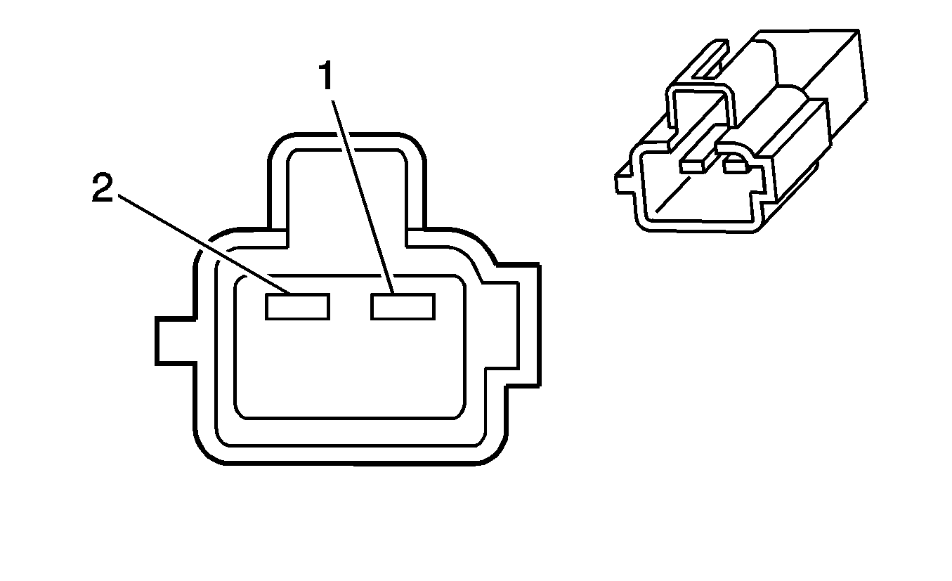
1 | OG/BK | 149 | Courtesy Lamps Supply Voltage | 2 | OG/BK | 149 | Courtesy Lamps Supply Voltage | ||||||||
2 | WH/GN | 660 | Left Courtesy Lamp Control | 1 | BN | 660 | Left Courtesy Lamp Control | ||||||||
|
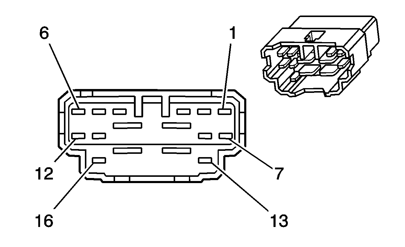
| ||||||||||||||
|---|---|---|---|---|---|---|---|---|---|---|---|---|---|---|---|
Connector Part Information |
| Connector Part Information |
| ||||||||||||
Pin | Wire Color | Circuit No. | Function | Pin | Wire Color | Circuit No. | Function | ||||||||
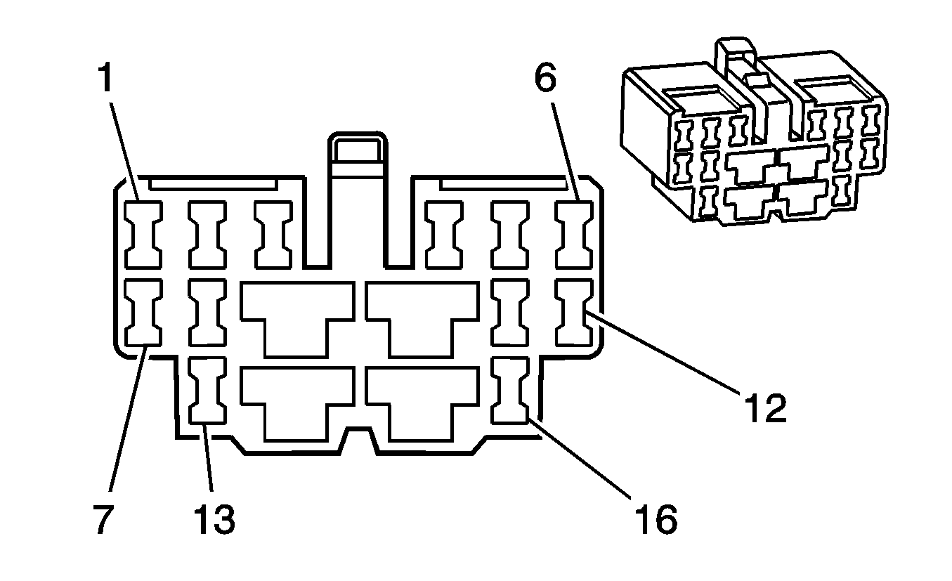
1 | PU | 881 | Passenger Mirror Motor - Right Control | 1 | PU | 881 | Passenger Mirror Motor - Right Control | ||||||||
2 | BK/BU | 650 | Ground | 2 | BK/BU | 650 | Ground | ||||||||
3 | L-GN | 200 | Right Front Speaker Output (+) | 3 | L-GN | 200 | Right Front Speaker Output (+) | ||||||||
4 | GN | 117 | Right Front Speaker Output (-) | 4 | GN | 117 | Right Front Speaker Output (-) | ||||||||
5 | BK/RD | 294 | Door Lock Actuator - Unlock Control | 5 | BK/RD | 294 | Door Lock Actuator - Unlock Control | ||||||||
6 | BK/YE | 295 | Door Lock Actuator - Lock Control | 6 | BK/YE | 295 | Door Lock Actuator - Lock Control | ||||||||
7 | GY | 1832 | Passenger Mirror Motor Up Signal | 7 | GY | 1832 | Passenger Mirror Motor Up Signal | ||||||||
8 | BN/OG | 194 | Door Unlock Control | 8 | BN/OG | 194 | Door Unlock Control | ||||||||
9 | -- | -- | Not Used | 9 | -- | -- | Not Used | ||||||||
10 | BN/RD | 195 | Door Lock Control | 10 | BN/RD | 195 | Door Lock Control | ||||||||
11 | PU/WH | 5171 | Folding Seat - Horizontal Position Sensor Signal | 11 | PU/WH | 5171 | Folding Seat - Horizontal Position Sensor Signal | ||||||||
12 | BN | 330 | Passenger Mirror Motor Supply Voltage | 12 | BN | 330 | Passenger Mirror Motor Supply Voltage | ||||||||
13 | WH/GN | 660 | Left Courtesy Lamp Control | 13 | WH/GN | 660 | Left Courtesy Lamp Control | ||||||||
14 | GN/OG | 667 | Power Window Motor - Right Front Down Control | 14 | GN/OG | 667 | Power Window Motor - Right Front Down Control | ||||||||
15 | BU/WH | 666 | Power Window Motor - Right Front Up Control | 15 | GN | 666 | Power Window Motor - Right Front Up Control | ||||||||
16 | OG/BK | 149 | Courtesy Lamps Supply Voltage | 16 | OG/BK | 149 | Courtesy Lamps Supply Voltage | ||||||||
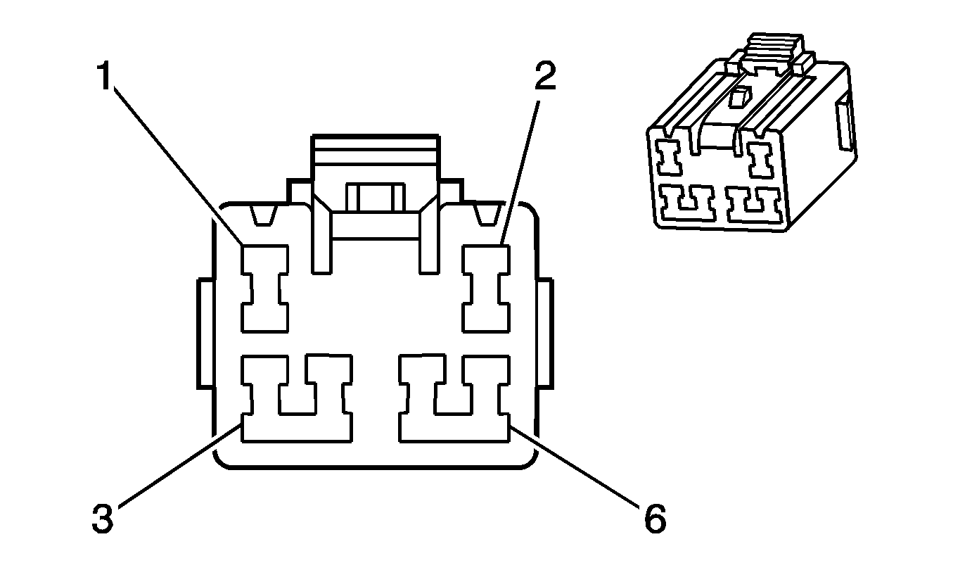
|
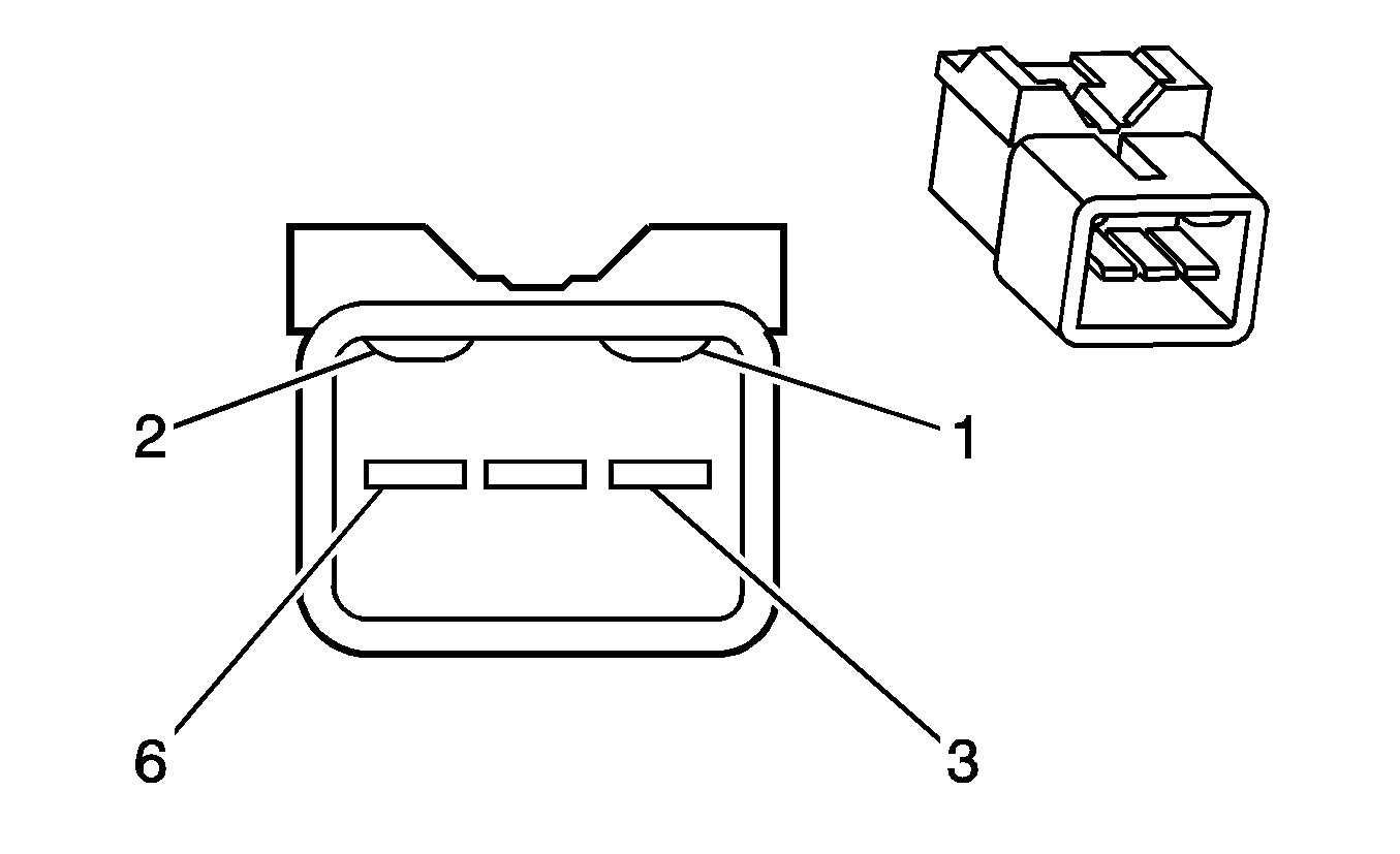
| ||||||||||||||
|---|---|---|---|---|---|---|---|---|---|---|---|---|---|---|---|
Connector Part Information |
| Connector Part Information |
| ||||||||||||
Pin | Wire Color | Circuit No. | Function | Pin | Wire Color | Circuit No. | Function | ||||||||
1 | BK/BU | 650 | Ground | 1 | BK/BU | 650 | Ground | ||||||||
2 | BN/WH | 650 | Ground | 2 | BK/BU | 650 | Ground | ||||||||
3 | BU | 1315 | Right Rear Turn Signal Lamp Supply Voltage | 3 | BU | 1315 | Right Rear Turn Signal Lamp Supply Voltage | ||||||||
4 | L-GN | 24 | Backup Lamp Supply Voltage | 4 | L-GN | 24 | Backup Lamp Supply Voltage | ||||||||
5 | BU/RD | 20 | Stop Lamp Supply Voltage | 5 | BU/RD | 20 | Stop Lamp Supply Voltage | ||||||||
6 | BN | 9 | Park Lamps Supply Voltage | 6 | BN | 9 | Park Lamps Supply Voltage | ||||||||

|

| ||||||||||||||
|---|---|---|---|---|---|---|---|---|---|---|---|---|---|---|---|
Connector Part Information |
| Connector Part Information |
| ||||||||||||
Pin | Wire Color | Circuit No. | Function | Pin | Wire Color | Circuit No. | Function | ||||||||
1 | BK/BU | 650 | Ground | 1 | BK/BU | 650 | Ground | ||||||||
2 | BN/WH | 650 | Ground | 2 | BK/BU | 650 | Ground | ||||||||
3 | L-BU | 1314 | Left Rear Turn Signal Lamp Supply Voltage | 3 | L-BU | 1314 | Left Rear Turn Signal Lamp Supply Voltage | ||||||||
4 | L-GN | 24 | Backup Lamp Supply Voltage | 4 | L-GN | 24 | Backup Lamp Supply Voltage | ||||||||
5 | BU/RD | 20 | Stop Lamp Supply Voltage | 5 | BU/RD | 20 | Stop Lamp Supply Voltage | ||||||||
6 | BN | 9 | Park Lamps Supply Voltage | 6 | BN | 9 | Park Lamps Supply Voltage | ||||||||
