Tools Required
| • | J 45059 Angle Meter |
| • | J 42385-100 Head/Main Bolt Thread Repair Kit |
Removal Procedure
- Remove the valve rocker arms and pushrods. Refer to Valve Rocker Arm and Push Rod Replacement .
- Remove the engine coolant air bleed pipe and covers. Refer to Coolant Air Bleed Pipe Assembly Replacement in Engine Cooling.
- Remove the exhaust manifold. Refer to Exhaust Manifold Replacement - Right Side in Engine Exhaust.
- Remove the intake manifold. Refer to Intake Manifold Replacement .
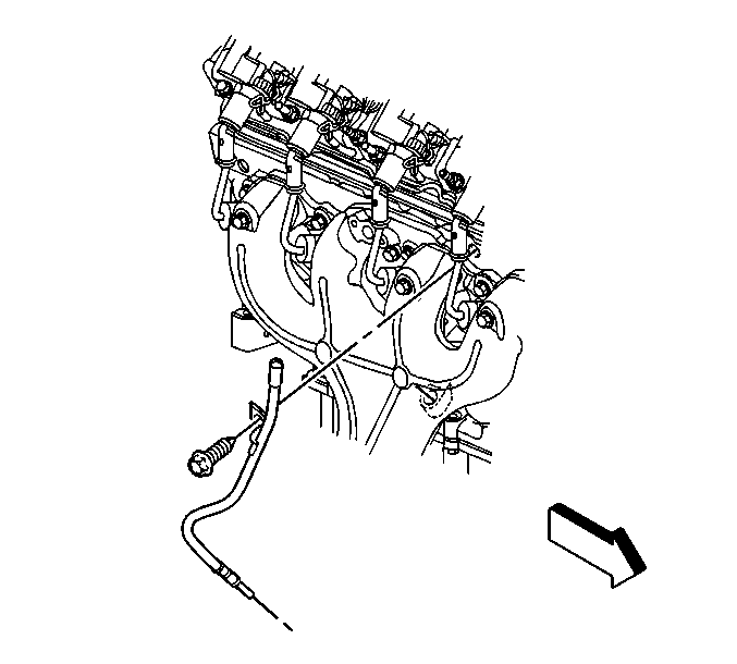
- Remove the oil level indicator tube bolt.
- Reposition the oil level indicator tube, if necessary.
- Remove the wiring harness from the clip at the rear of the cylinder head.
- Remove the cylinder head bolts.
- Remove the cylinder head (218).
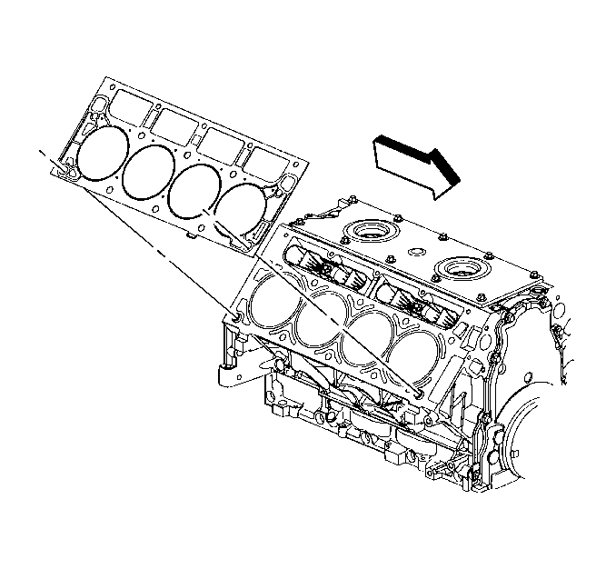
- Remove the cylinder head gasket.
- Discard the gasket.
- Discard the cylinder head bolts.
- Clean and inspect the cylinder head. Refer to Cylinder Head Cleaning and Inspection .
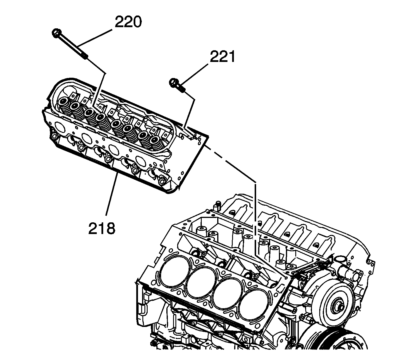
Important: The cylinder head bolts are NOT reusable.
Notice: After removal, place the cylinder head on 2 wood blocks in order to prevent damage to the sealing surfaces.
Installation Procedure
Caution: Refer to Safety Glasses Caution in the Preface section.
Notice: Refer to Cleaning Engine Block Cylinder Head Bolt Holes Notice in the Preface section.
- Clean the engine block cylinder head bolt holes, if required.
- Spray cleaner GM P/N 12346139 (Canadian P/N 10953463), GM P/N 12377981 (Canadian P/N 10953463), or equivalent into the hole.
- Clean the cylinder head bolt holes with compressed air.
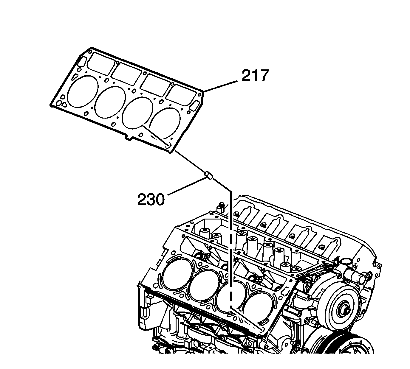
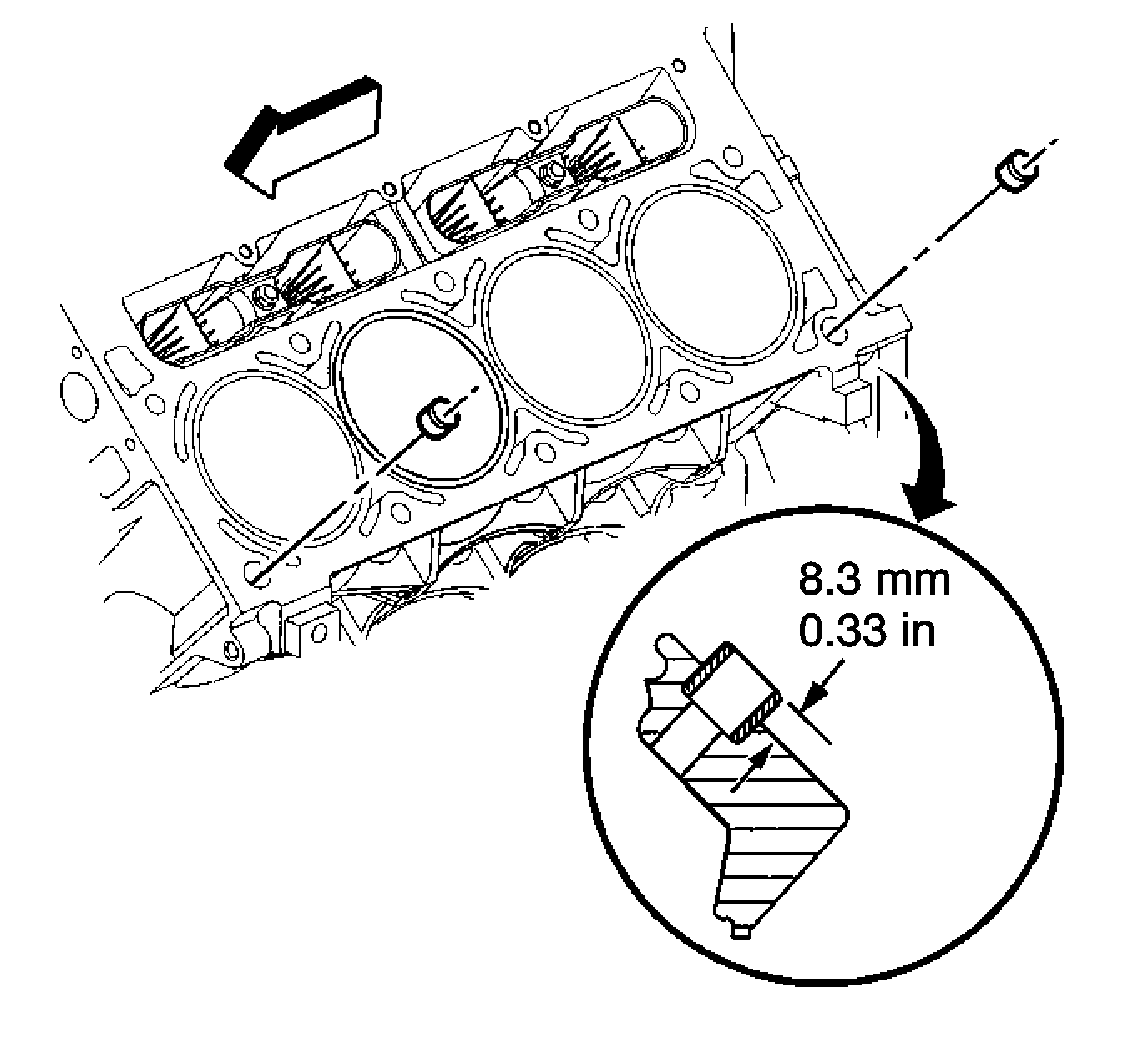
- Install the cylinder head locating pins (230).
- Inspect the locating pins for proper installation.
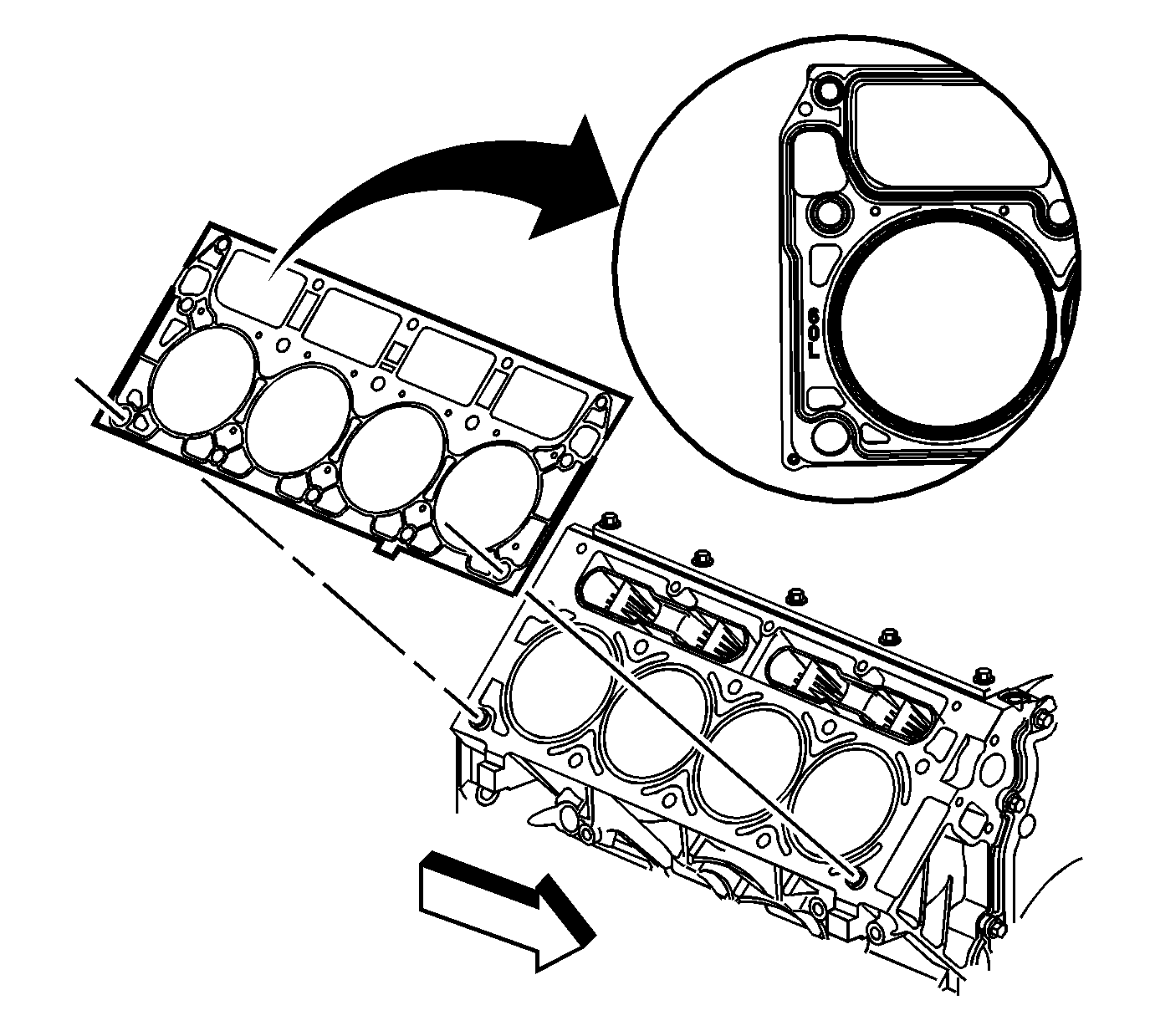
- Inspect the displacement markings on the gasket for proper usage.
- Install the NEW cylinder head gasket (217) onto the locating pins.
- Install the cylinder head (218) onto the locating pins and the gasket.
- Install the NEW cylinder head bolts (219, 220).
- Tighten the cylinder head bolts.
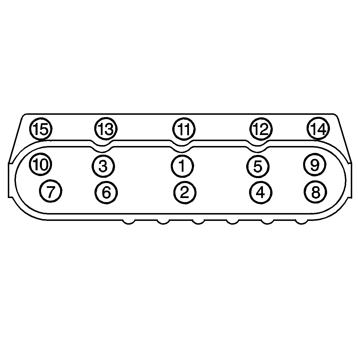
- Tighten the M11 cylinder head bolts (1-10) a first pass in sequence to 30 N·m (22 lb ft).
- Tighten the M11 cylinder head bolts (1-10) a second pass in sequence to 90 degrees using the J 45074 .
- Tighten the M11 cylinder head bolts (1-10) a final pass in sequence to 70 degrees using the J 45074 .
- Tighten the M8 cylinder head bolts (11-15) to 30 N·m (22 lb ft). Begin with the center bolt (11) and alternating side-to-side, work outward tightening all of the bolts.
- Install the intake manifold. Refer to Intake Manifold Replacement .
- Install the wiring harness to the clip at the rear of the cylinder head.
- Position the oil level indicator tube into place.
- Install the oil level indicator tube bolt.
- Install the exhaust manifold. Refer to Exhaust Manifold Replacement - Right Side in Engine Exhaust.
- Install the engine coolant air bleed pipe. Refer to Coolant Air Bleed Pipe Assembly Replacement in Engine Cooling.
- Install the valve rocker arms and pushrods. Refer to Valve Rocker Arm and Push Rod Replacement .
Important:
• Do not use the cylinder head bolts again. Install NEW cylinder head bolts during assembly. • Do not use any type of sealant on the cylinder head gasket, unless specified. • The cylinder head gaskets must be installed in the proper direction and position.
Thread repair tool J 42385-107 may be used to clean the threads of old threadlocking material.


Notice: Refer to Fastener Notice in the Preface section.
Tighten

Tighten
Tighten the oil level indicator tube bolt to 25 N·m (18 lb ft).
