For 1990-2009 cars only
Removal Procedure
- Disconnect the negative battery cable.
- Remove the left instrument panel (I/P) lower insulator panel. Refer to Instrument Panel Insulator Panel Replacement - Left Side in Instrument Panel, Gages and Console.
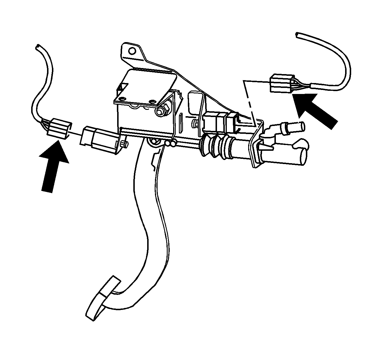
- Disconnect the clutch pedal position (CPP) and the clutch start switch electrical connectors.
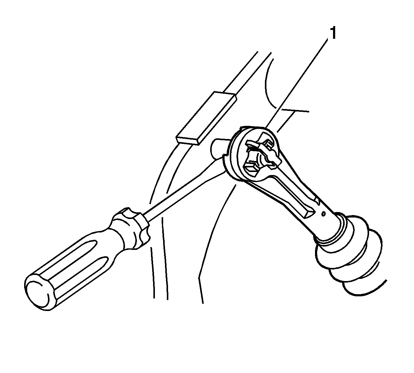
- Disconnect the clutch master cylinder push rod (1) from the clutch pedal assembly.
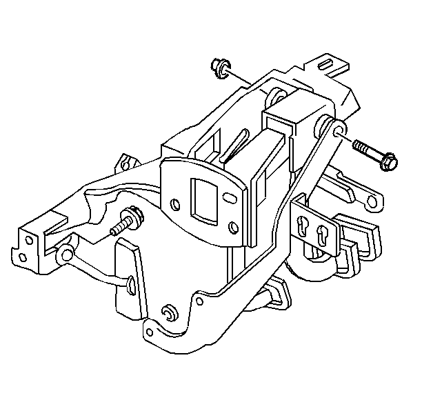
- From inside the engine compartment, remove the 2 clutch master cylinder retaining nuts.
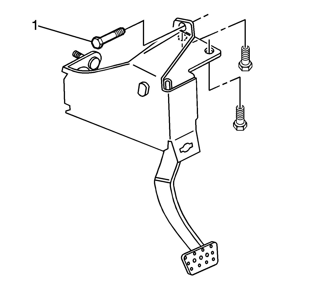
- Remove the 3 clutch pedal assembly retaining bolts (1).
- Lower the clutch pedal assembly from the instrument panel.
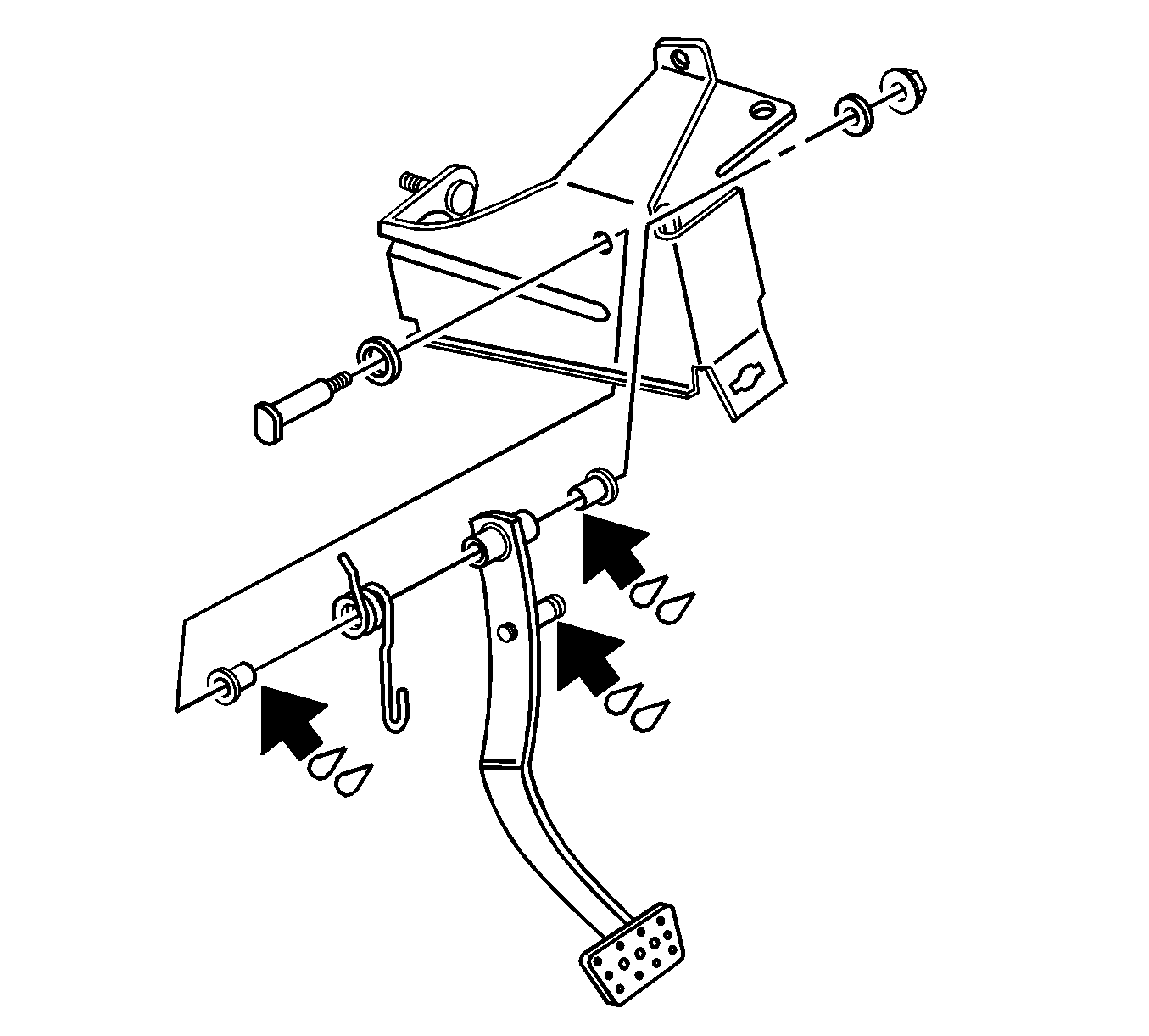
- Remove the clutch pivot bolt retaining nut and washer.
- Carefully remove the clutch pivot bolt from the clutch support.
- Remove the clutch pedal and return spring.
- Release the end of the return spring from the clutch pedal.
- Remove the return spring and the 2 pivot bushings from the clutch pedal.
Caution: Refer to Battery Disconnect Caution in the Preface section.
Installation Procedure
- Lubricate the 2 bushings with Dri-Slide Lubricant GM P/N 1052948.
- Install the return spring and the 2 pivot bushings on the clutch pedal.
- Position the clutch pedal on the clutch pedal support, then install the clutch pedal pivot bolt and washer.
- Install the clutch pivot retaining nut and washer.
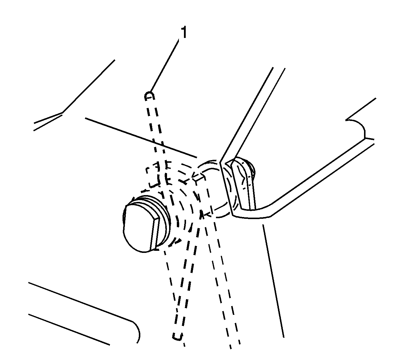
- Position the end (1) of the clutch pedal return spring as shown.
- Install the clutch bracket retaining bolts (1).
- Install the clutch master cylinder retaining nuts.
- Position the clutch pedal bracket in the vehicle
- Install the clutch master cylinder push rod (1) to the clutch pedal pivot pin.
- Connect the CPP and the clutch start switch electrical connectors.
- Install the left I/P lower insulator panel. Refer to Instrument Panel Insulator Panel Replacement - Left Side in Instrument Panel, Gages and Console.
- Connect the negative battery cable.

Notice: Refer to Fastener Notice in the Preface section.
Tighten
Tighten the clutch pivot nut to 15 N·m
(11 lb ft).
Tighten
Tighten the clutch bracket retaining bolts to 25 N·m
(18 lb ft).
Tighten
Tighten the clutch master cylinder retaining nuts
to 25 N·m (18 lb ft).

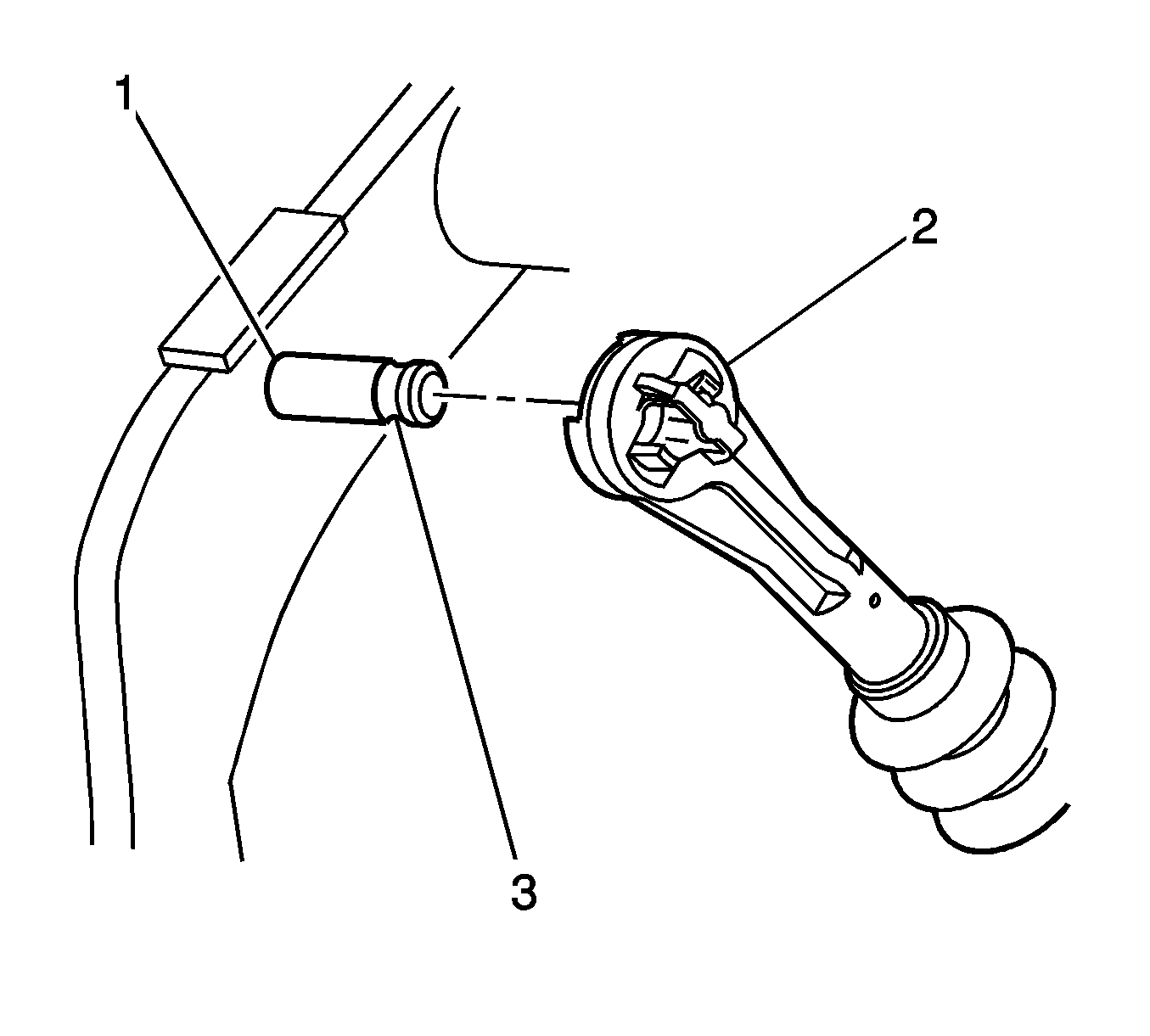
Important: Ensure the quick connect retaining clips are fully engaged in the groove (3).

