Transmission Disassemble CTS and GTO
Extension Housing Removal
Tools Required
| • | J 39430
Transmission Holding Fixture |
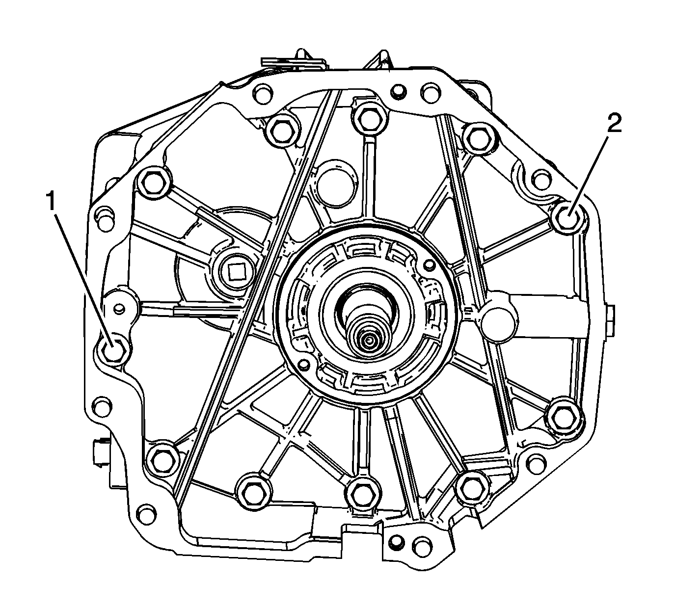
- Remove the adapter plate bolts (1) and (2).
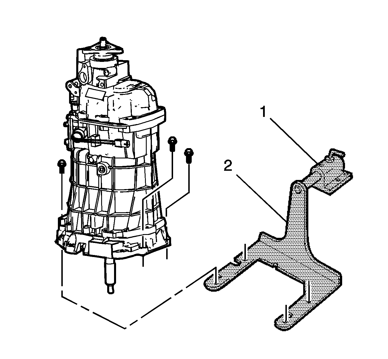
- Install the
J 39430
(2) .
- Mount the transmission on a workbench using the
J 3289-20
(1) .
- Rotate the transmission into a horizontal position.
- Remove the transmission drain plug and drain the transmission fluid.
- Shift the transmission into NEUTRAL (N).
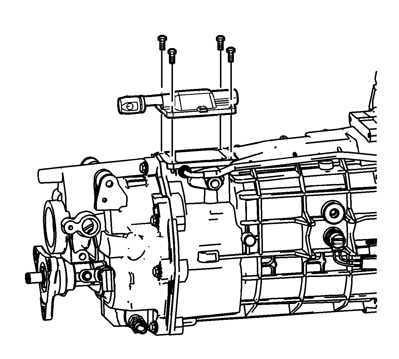
- Remove the shifter cover plate bolts.
- Remove the shifter cover plate.
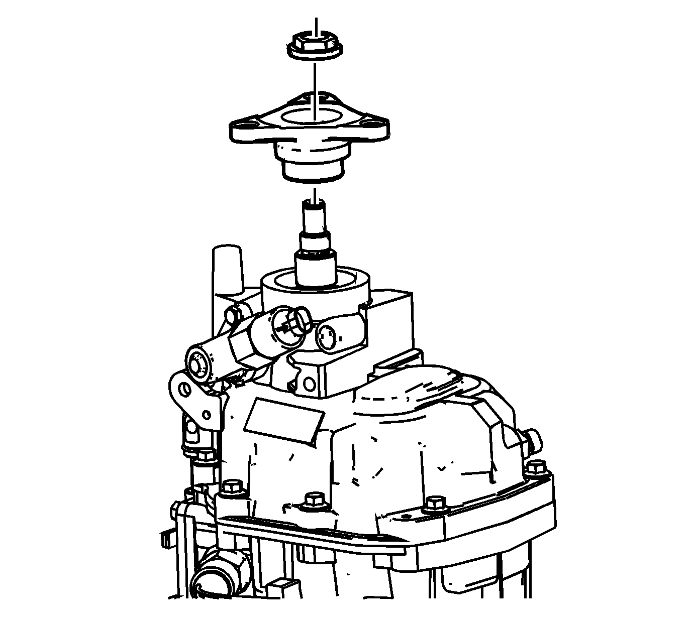
- Remove the propshaft connector bolt.
- Remove the propshaft.
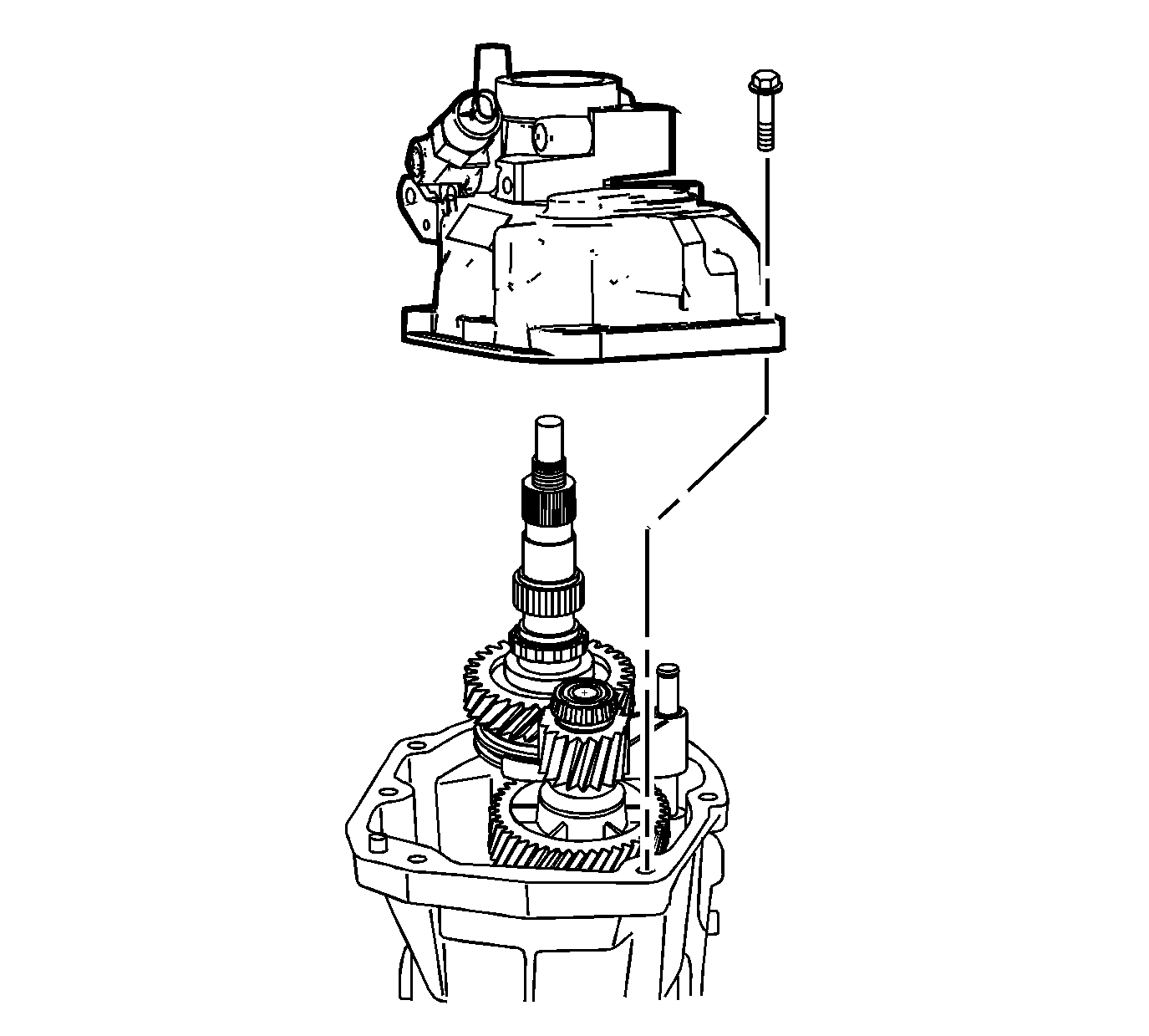
- Remove the rear extension housing bolts and the rear extension housing.
Reverse Speed Gear Removal
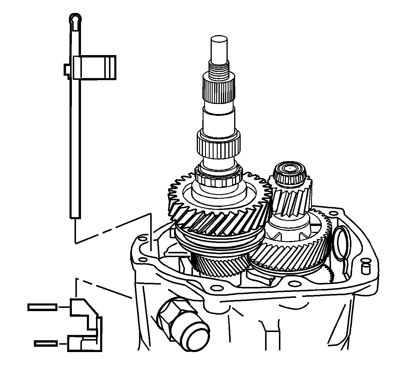
- Remove the shift guide rollpins.
- Remove the shift guide.
- Remove the shift shaft extension.
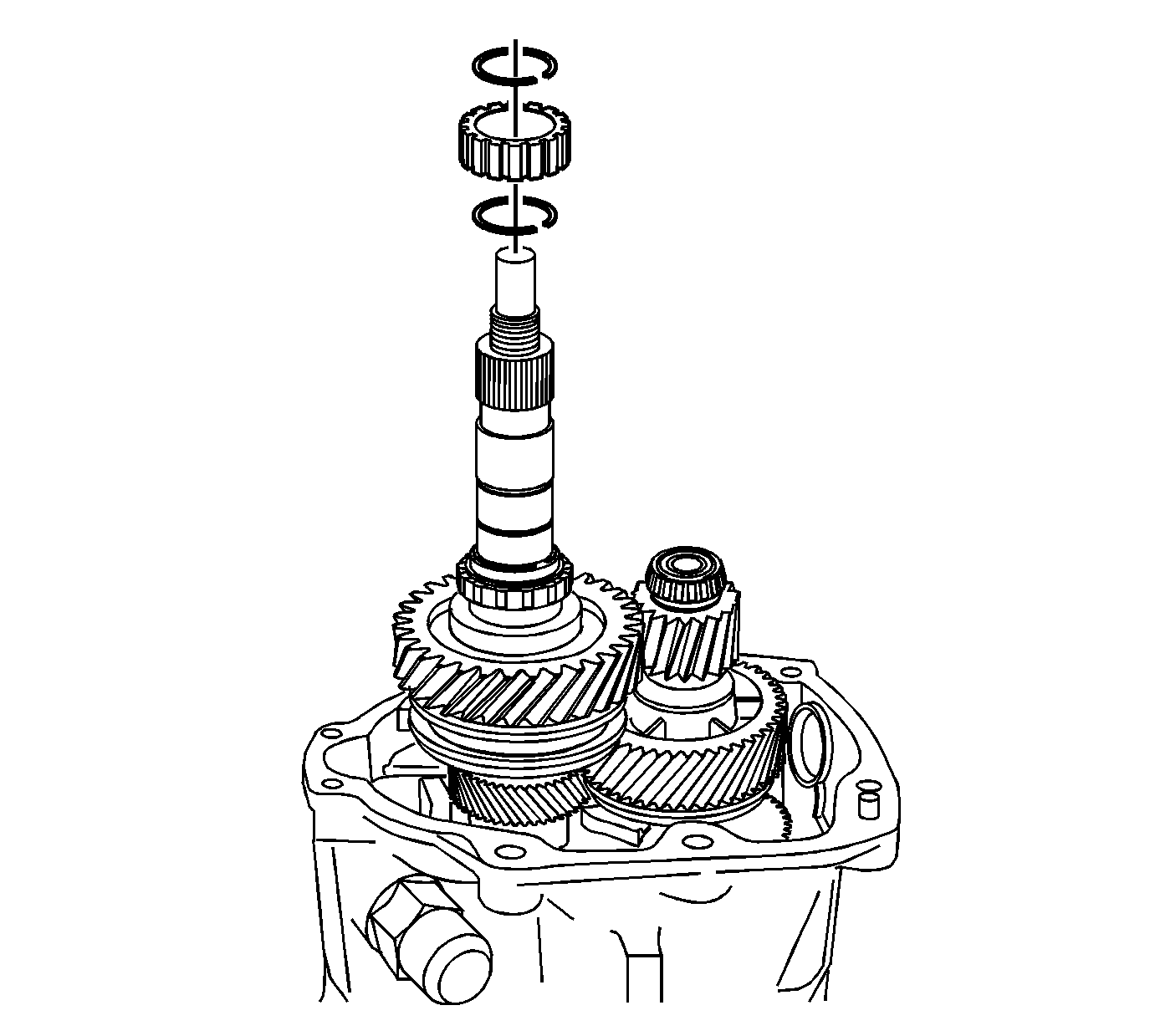
- Remove the following parts in order:
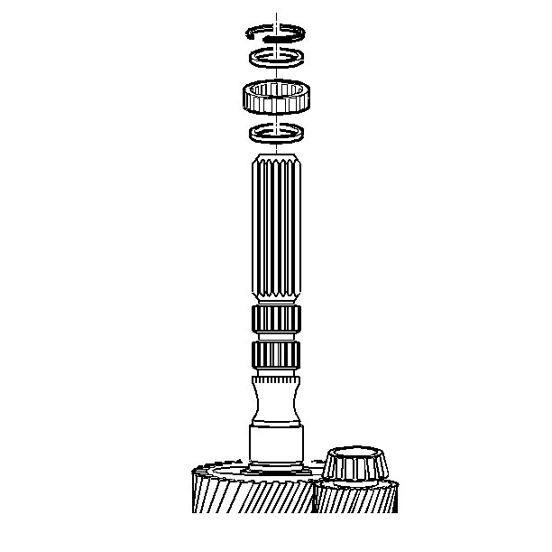
- Remove the rear bearing retainer ring.
- Remove the spacer.
- Remove the mainshaft rear roller bearing.
- Remove the spacer.
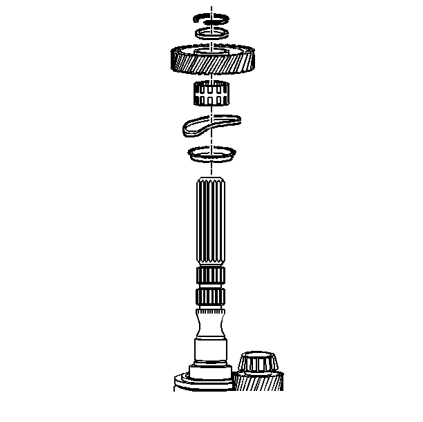
- Remove the retainer ring.
- Remove the reverse gear thrust washer.
- Remove the reverse gear.
- Remove the reverse gear caged needle bearing.
- Remove the wave washer.
- Remove the reverse gear synchronizer blocking ring.
Reverse Shift Fork Removal
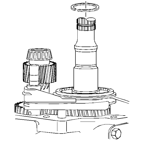
- Remove the reverse synchronizer retainer ring.
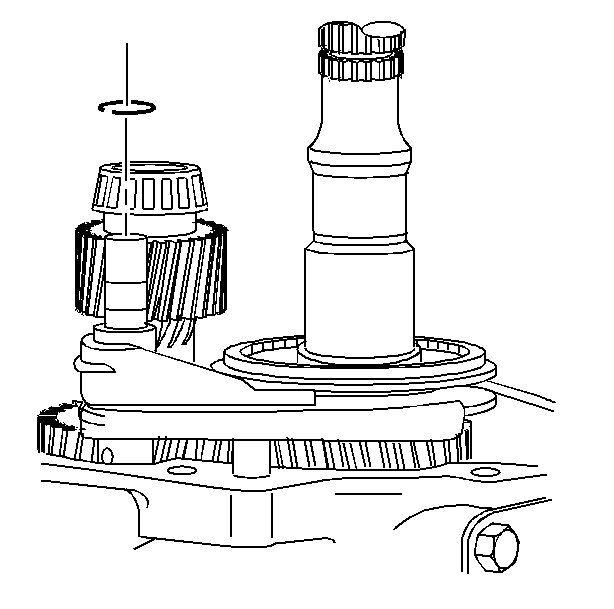
- Remove and discard the reverse shift fork retainer ring.
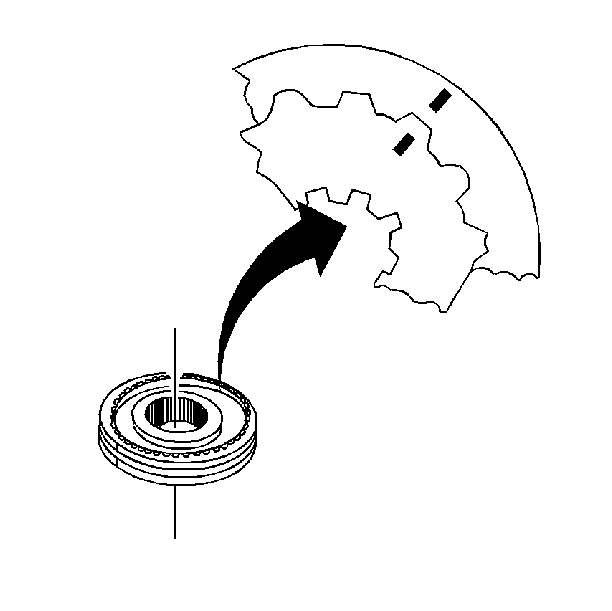
- Scribe a mark on the synchronizer hub and on the sleeve. This will help you to reinstall the parts in the same
position.
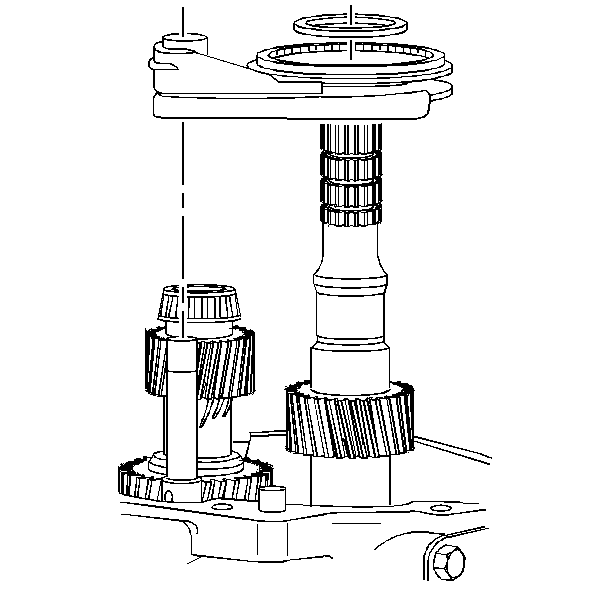
- Remove the following parts in order:
| 4.2. | The reverse synchronizer assembly and the shift fork |
5th/6th Speed Driven Gear Removal
Tools Required
| • | J 8433
Universal Bridge Puller |
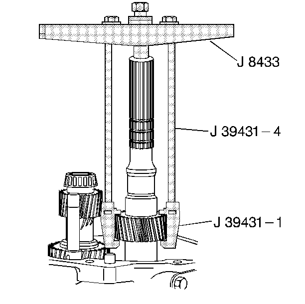
Remove the 5th/6th speed driven gear. Use the
J 8433
, the
J 39431
and the J 39431-4.
Countershaft Extension Removal
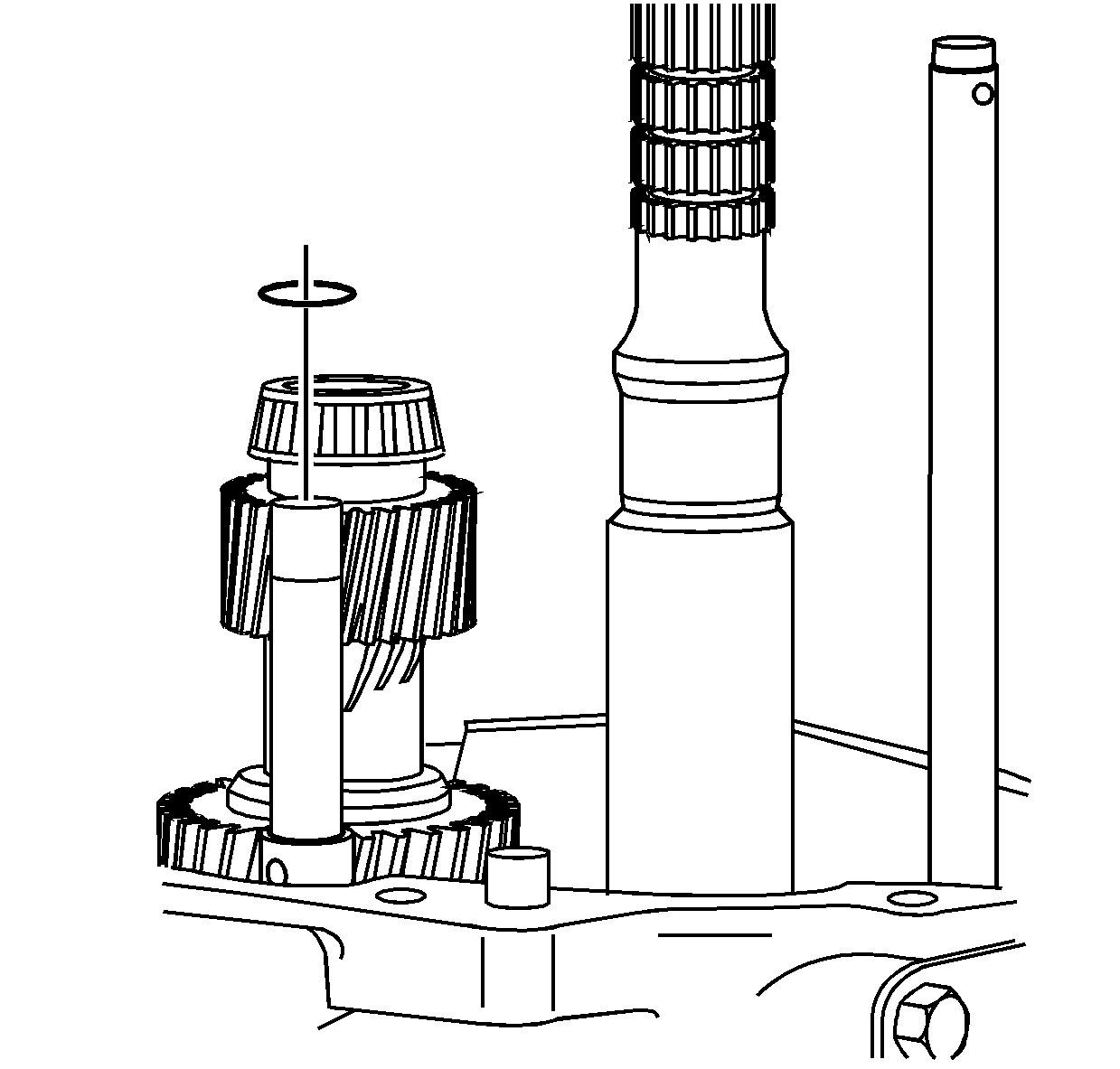
- Remove the 5th/6th speed shift fork retainer ring.
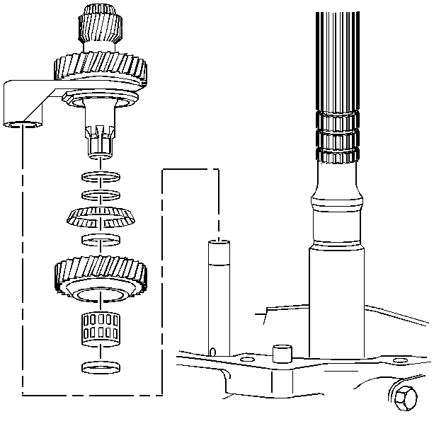
- Rotate the transmission in the horizontal position with the guide plate up.
- Remove the countershaft extension assembly with the 5th/6th speed shift fork, 6th speed gear bearing spacer, 6th speed drive gear, and caged needle bearing. The 6th speed gear bearing spacer will slide out during removal of the countershaft extension
assembly.
Transmission Case Removal
Tools Required
J 41099
Skip Shift Sensor Remover/ Installer
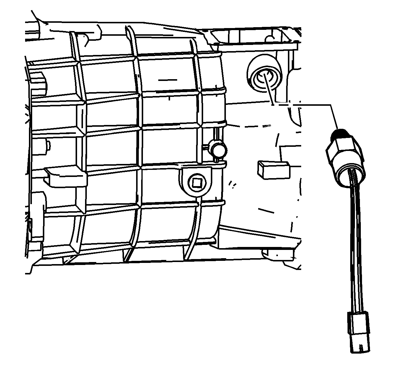
- Remove the computer aided gear select solenoid.
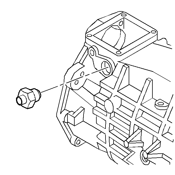
- Remove the shift detent assembly.
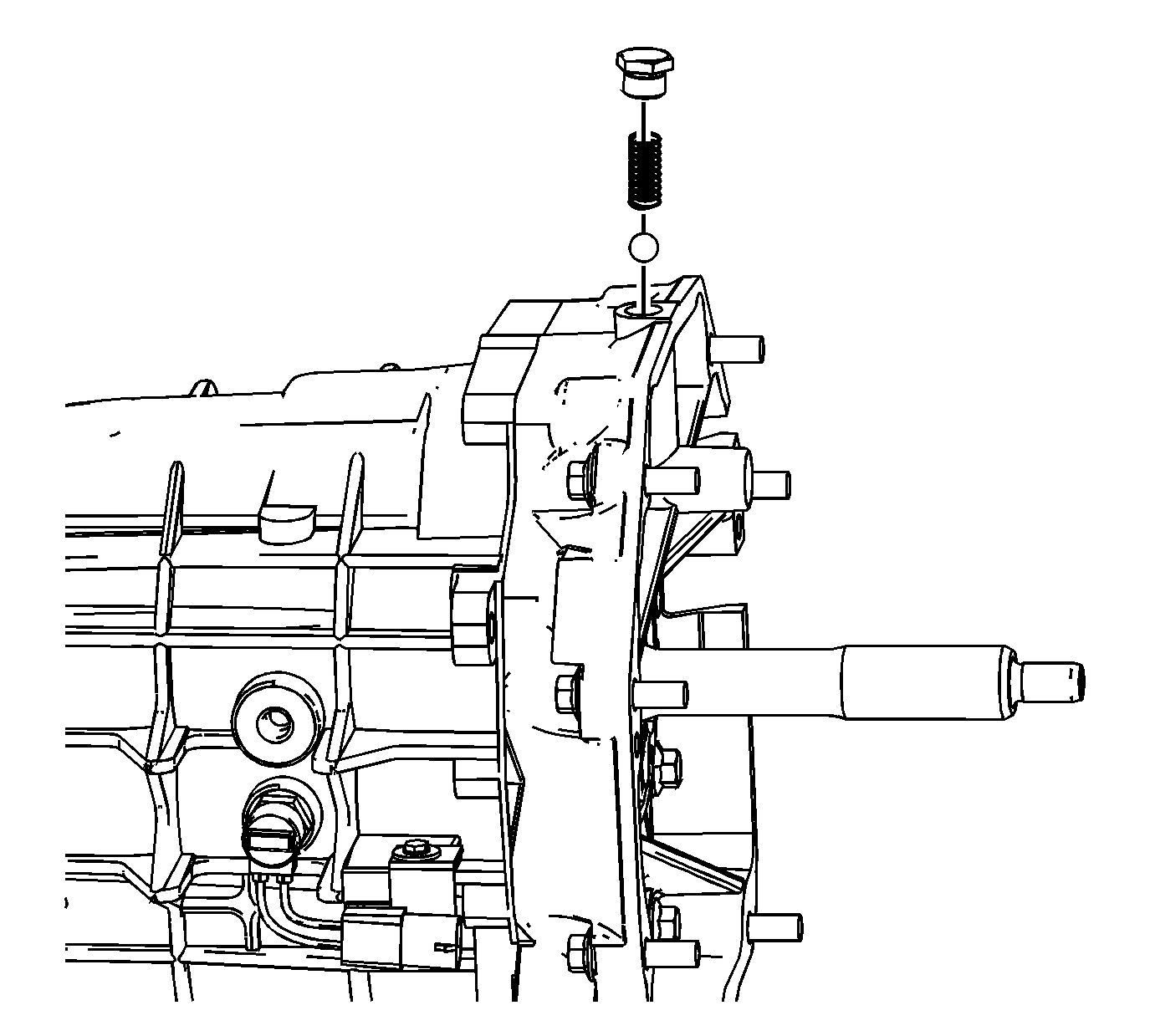
- Remove the shift detent plug, spring, and ball.
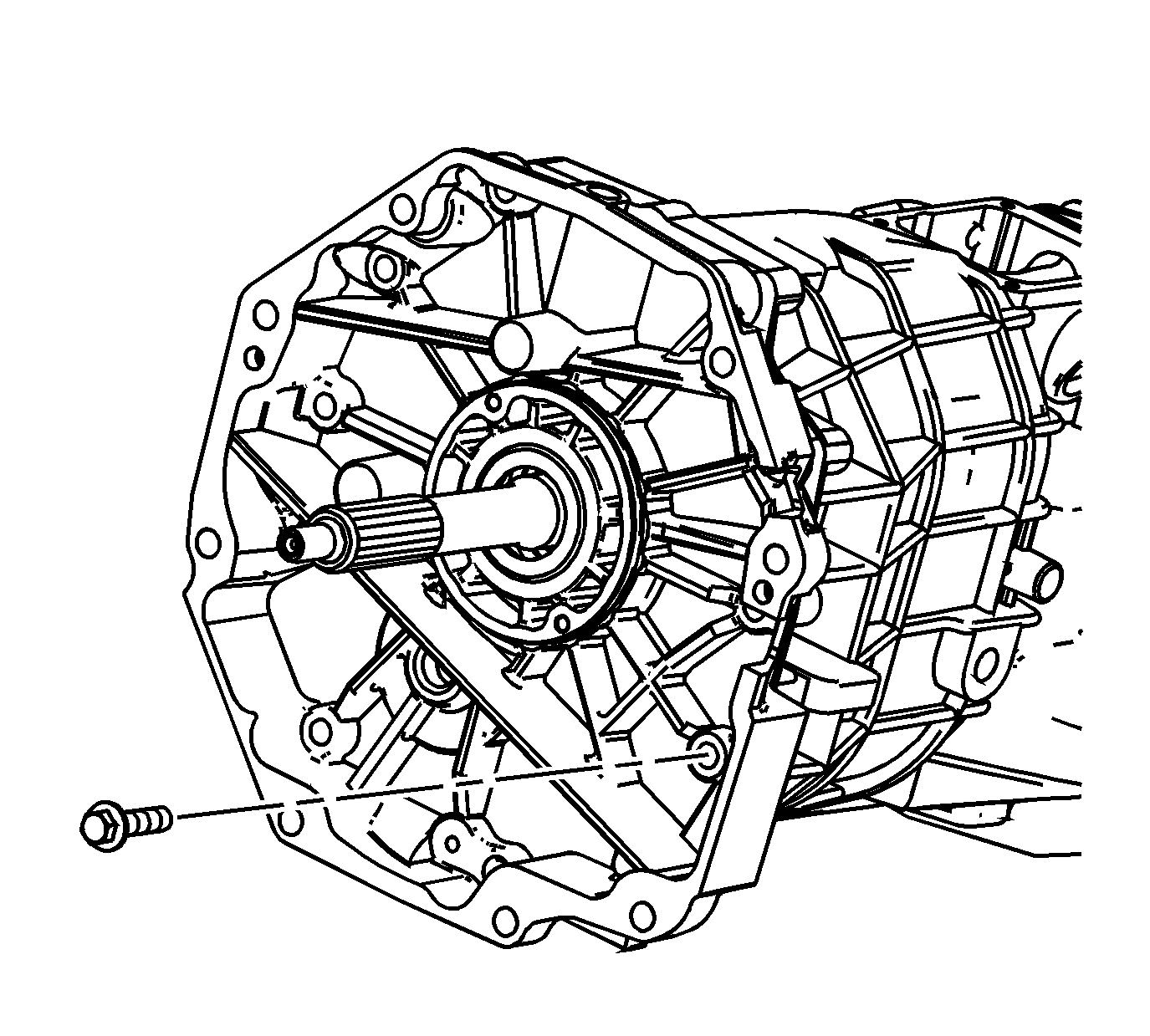
- Remove 9 of the 11 adapter plate to transmission case bolts.
- Rotate the transmission into the vertical position.
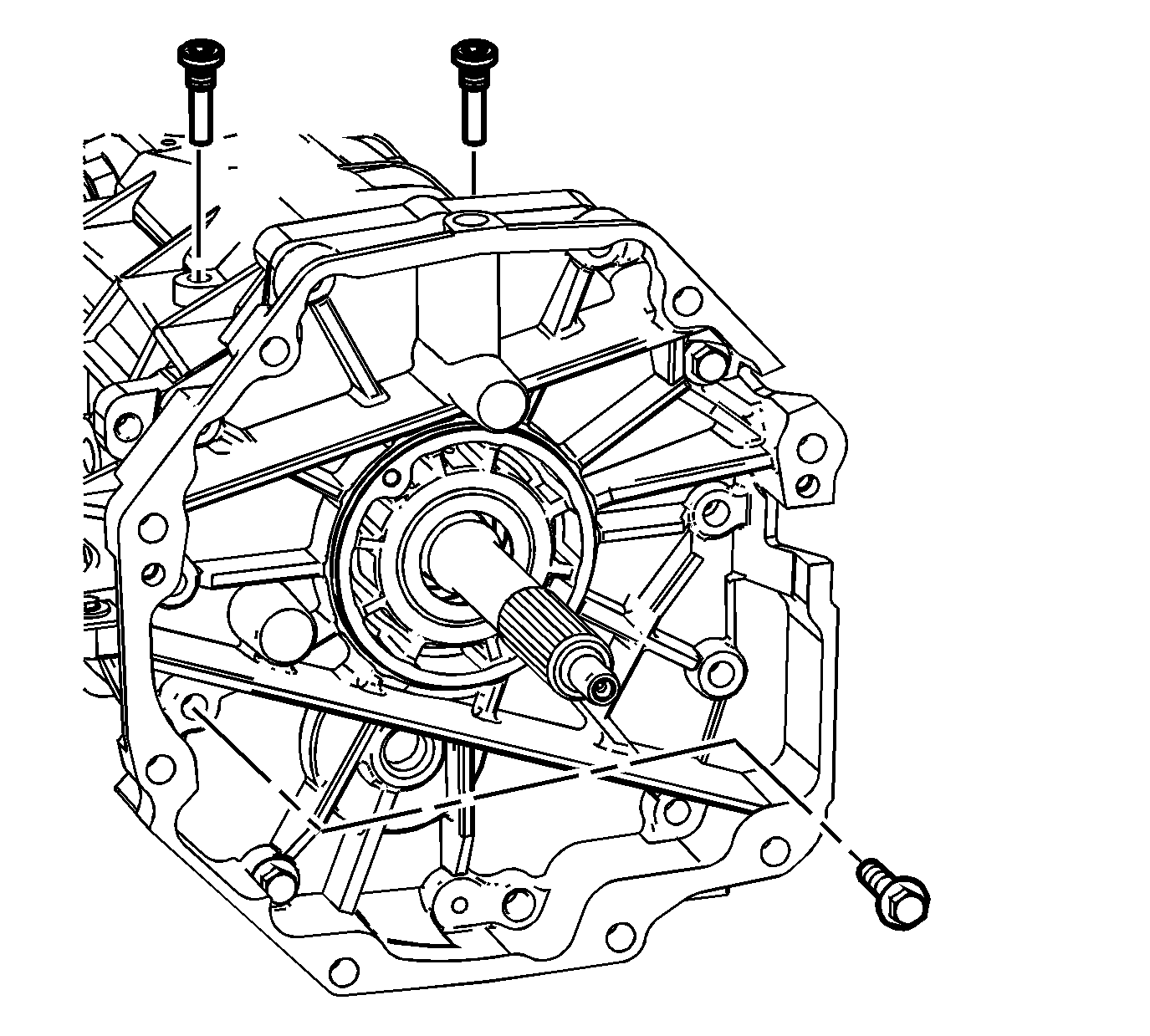
- Remove the last 2 adapter plate to transmission case bolts.
- Remove the shift lever guide bolts.
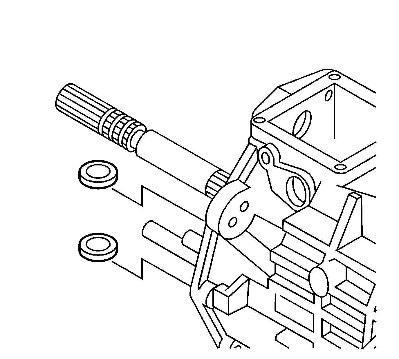
- Remove the magnets from the transmission case.
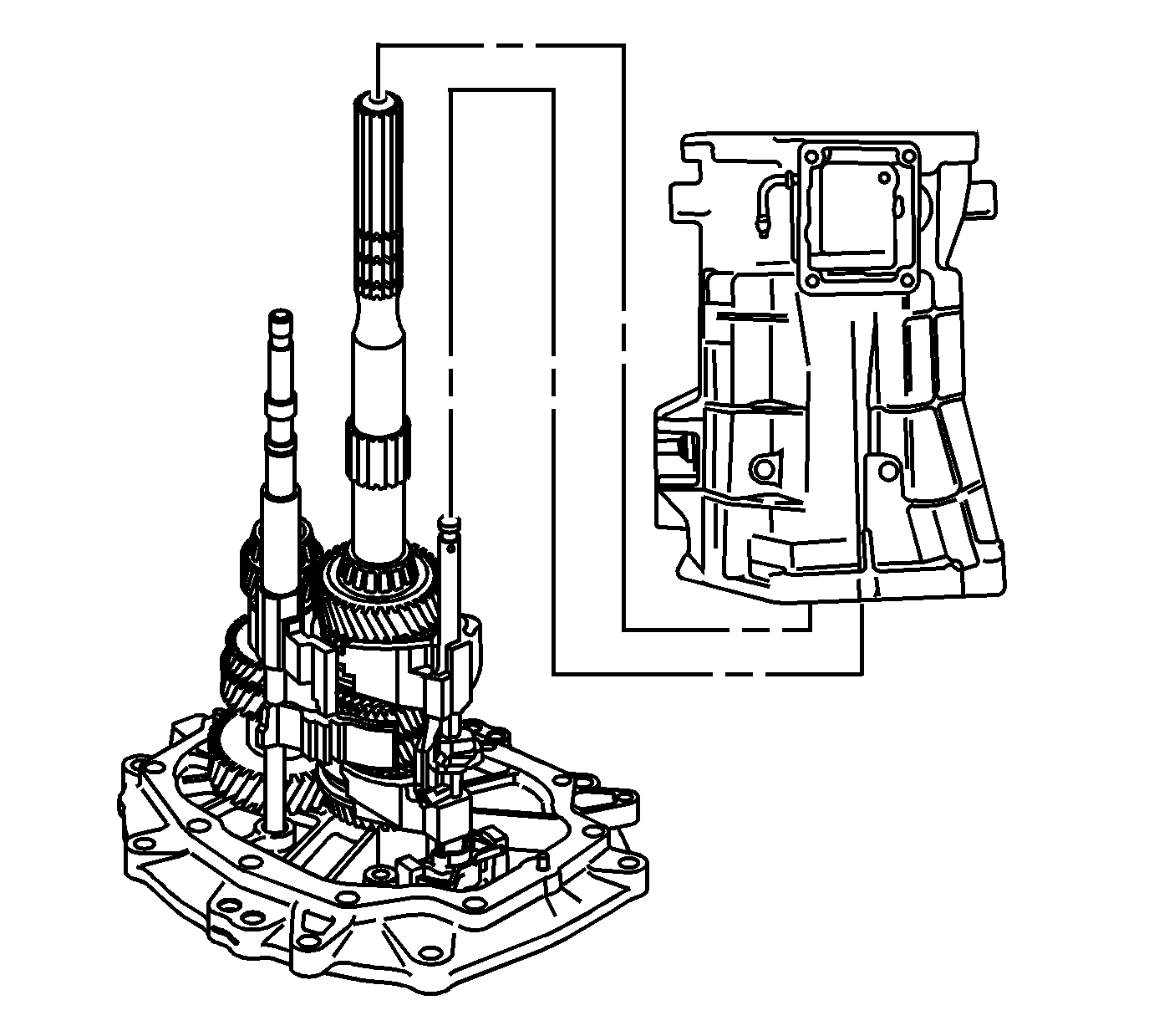
- Remove the transmission case and the offset lever together as follows:
| 9.1. | Slide the transmission case up and off of the gear clusters and the shift shaft components. |
| 9.2. | Hold the offset lever against the guide plate in order to prevent the release of the detent ball and the spring. |
| 9.3. | Remove the offset lever from the transmission case. |
Guide Plate Removal
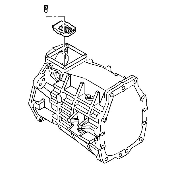
- Remove the detent guide plate attaching bolts.
- Remove the detent guide plate.
Shift Shaft Assemblies and Gear Cluster Removal
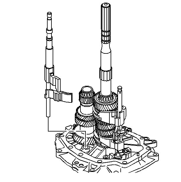
- Rotate the 5th/6th and the reverse shift shaft levers off the shift interlock plate.
- Remove the 5th/6th and the reverse shift shaft assembly.
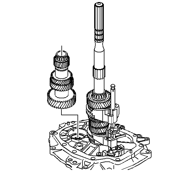
- Remove the countershaft. Lift up the mainshaft enough in order to remove the countershaft.
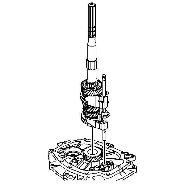
- Remove the mainshaft and the shift shaft components as an assembly.
Important: When removing the shift shaft be careful not to lose the dowel pin.
- Remove the shift shaft assembly from the mainshaft.
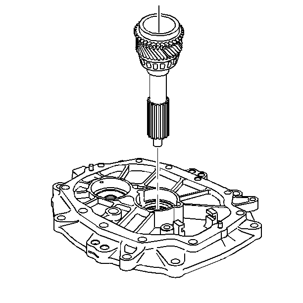
- Remove the input shaft.
Transmission Disassemble Corvette MM6 and MZ6
Extension Housing Removal
Tools Required
| • | J 44395
Transmission Holding Fixture |
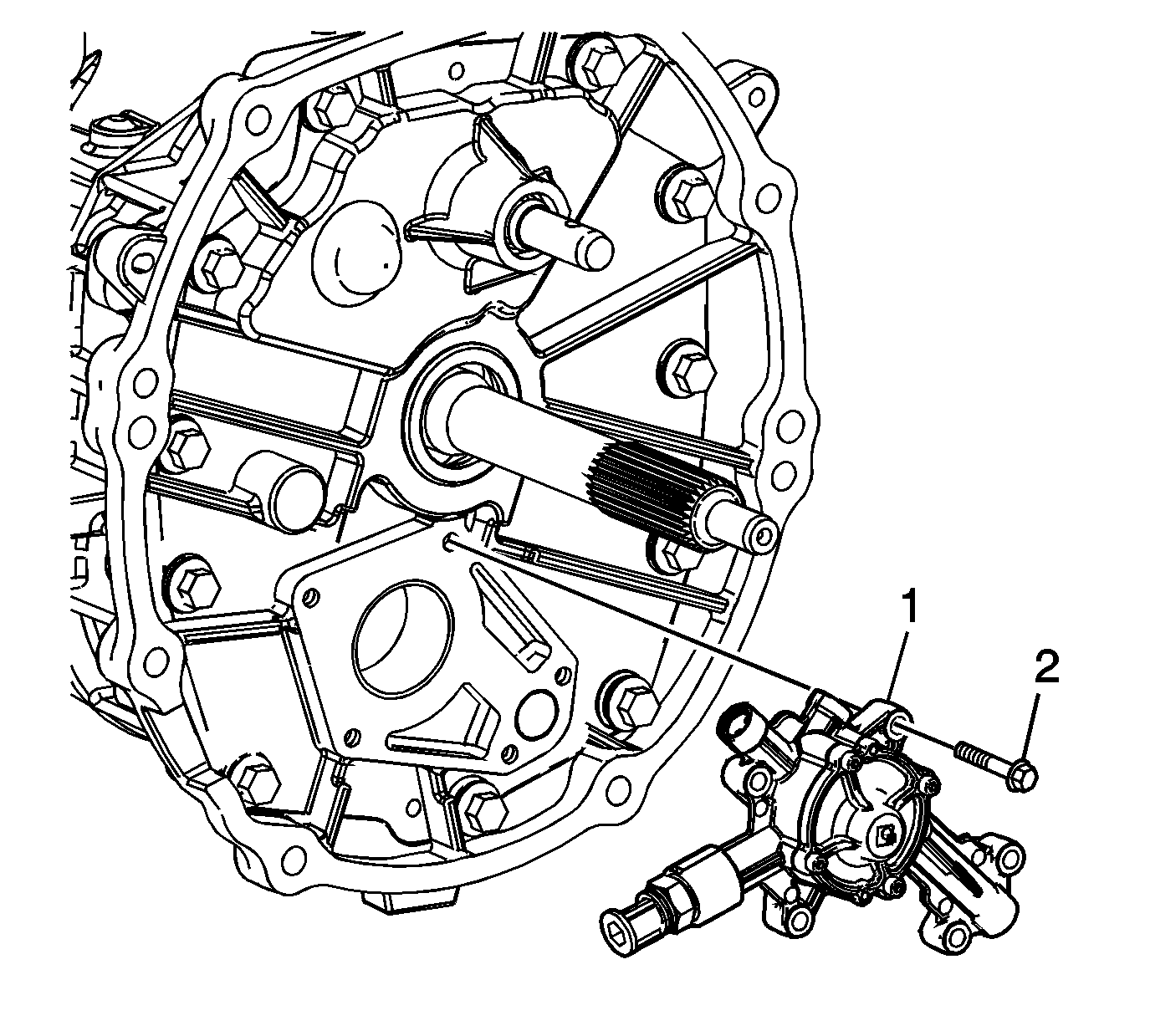
- Remove the auxiliary cooler pump bolt (2).
- Remove the auxiliary cooler pump (1) (MZ6 only).
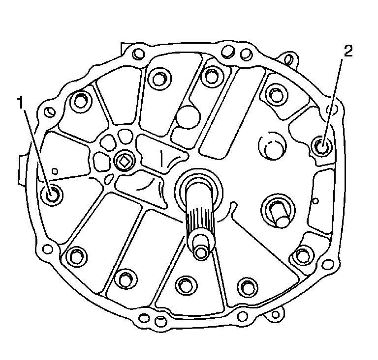
- Remove the adapter plate bolts (1) and (2).
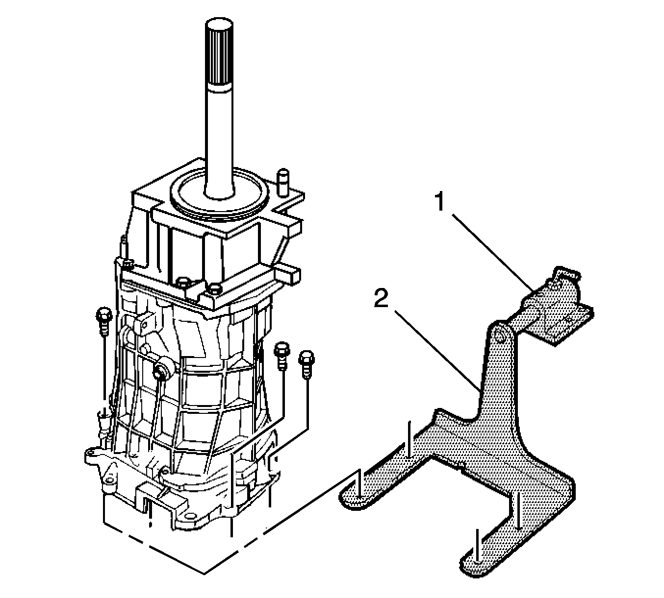
- Install the
J 44395
.
- Mount the transmission on a workbench using the
J 3289-20
.
- Rotate the transmission into a horizontal position.
- Remove the transmission drain plug and drain the transmission fluid.
- Shift the transmission into neutral (N).
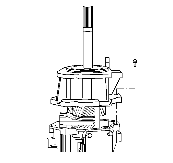
- Remove the rear extension housing bolts and the rear extension housing.
Reverse Speed Gear Removal

- Remove the rear bearing
retainer ring.
- Remove the spacer.
- Remove the mainshaft rear roller bearing.
- Remove the spacer.

- Remove the retainer ring.
- Remove the reverse gear thrust washer.
- Remove the reverse gear.
- Remove the reverse gear caged needle bearing.
- Remove the wave washer.
- Remove the reverse gear synchronizer blocking ring.
Reverse Shift Fork Removal

- Remove the reverse synchronizer
retainer ring.

- Remove and discard the reverse shift fork retainer ring.

- Scribe a mark on the synchronizer
hub and on the sleeve. This will help you to reinstall the parts in the same
position.

- Remove the following parts in order:
| 4.2. | The reverse synchronizer assembly and the shift fork |
5th/6th Speed Driven Gear Removal
Tools Required
| • | J 8433
Universal
Bridge Puller |

Remove the 5th/6th speed
driven gear. Use the
J 8433
,
the
J 39431
and
the J 39431-4.
Countershaft Extension Removal

- Remove the 5th/6th speed
shift fork retainer ring.

- Rotate the transmission in the horizontal position with the guide plate
up.
- Remove the countershaft extension assembly with the 5th/6th speed
shift fork, 6th speed gear bearing spacer, 6th speed drive gear, and caged
needle bearing. The 6th speed gear bearing spacer will slide out during removal
of the countershaft extension assembly.
Transmission Case Removal
Tools Required
J 41099
Skip Shift Sensor Remover/ Installer
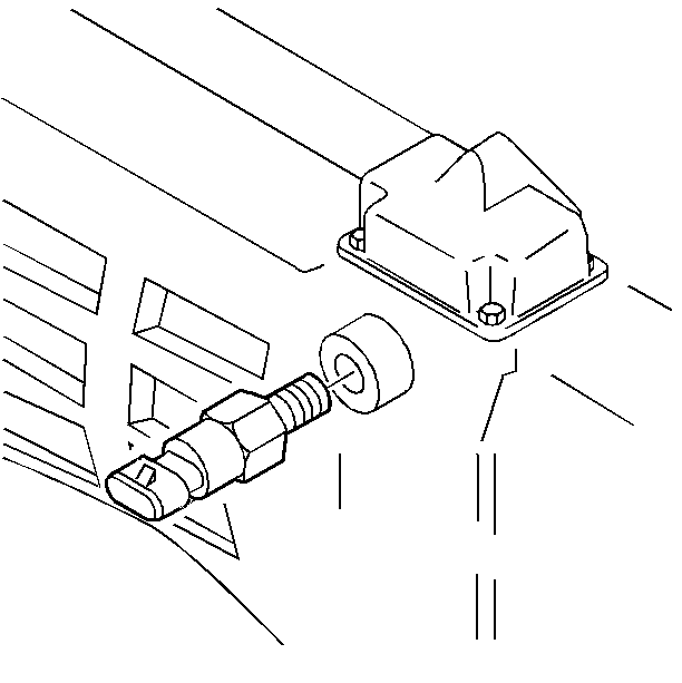
- Remove the computer aided gear select solenoid.
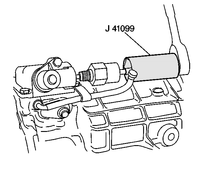
- Remove the reverse lockout solenoid from the reverse lockout body. Use the
J 41099
.
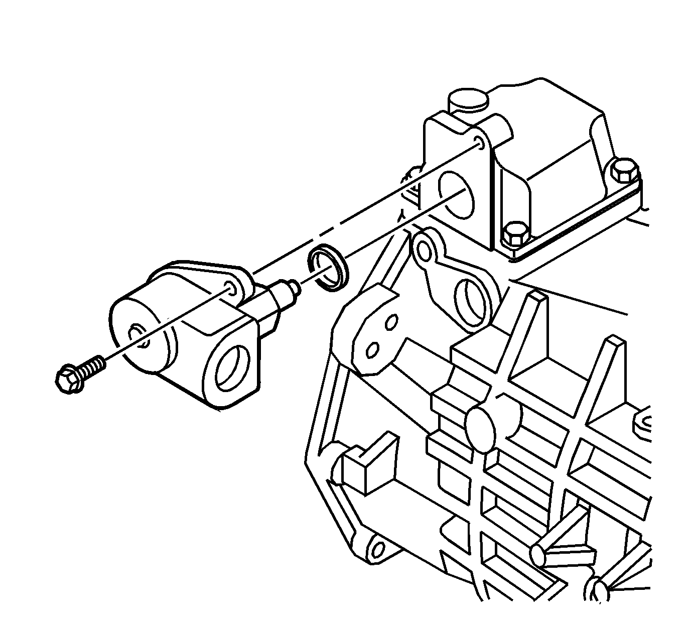
- Remove the reverse lockout assembly bolt, reverse lockout body, and O-ring.
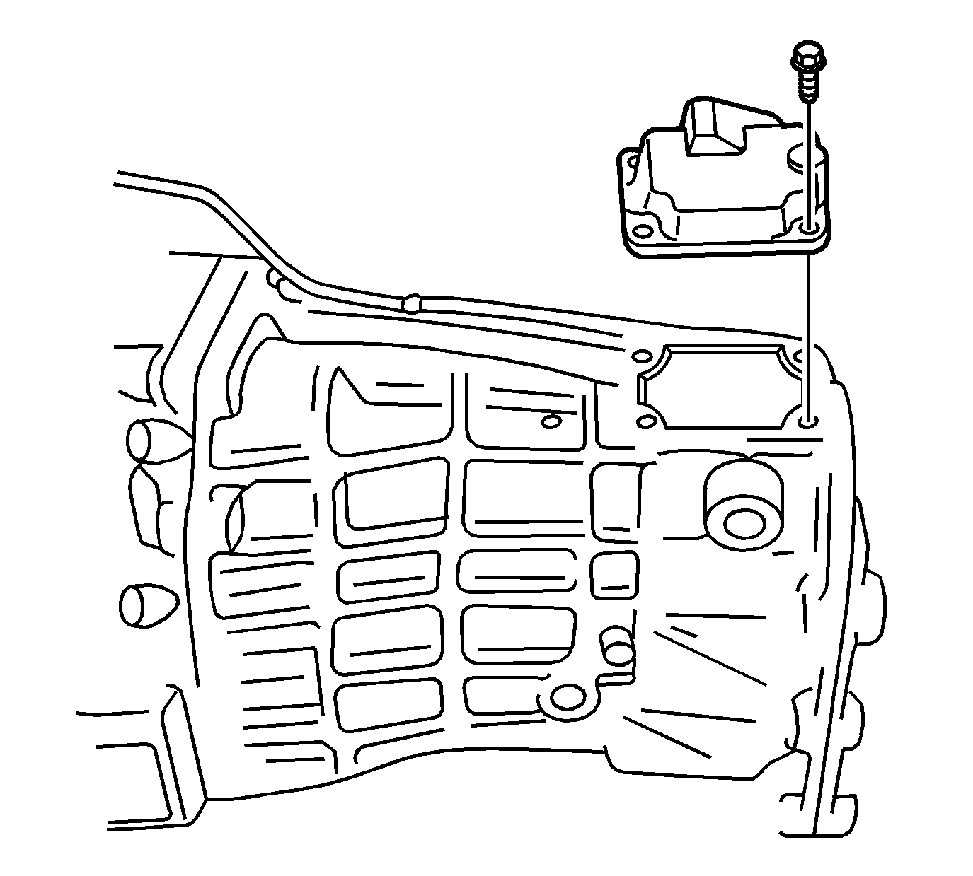
- Remove the shifter cover plate retainer bolts.
- Remove the shifter cover plate.

- Remove the shift detent assembly.
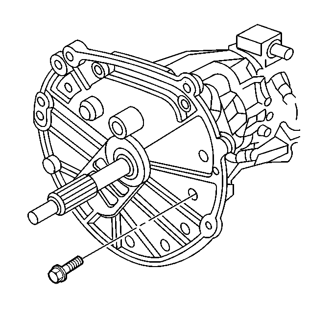
- Remove 9 of the 11 adapter plate to transmission case bolts.
- Rotate the transmission into the vertical position.
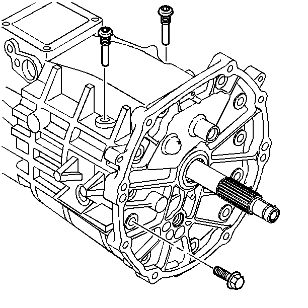
- Remove the last 2 adapter plate to transmission case bolts.
- Remove the shift lever guide bolts.
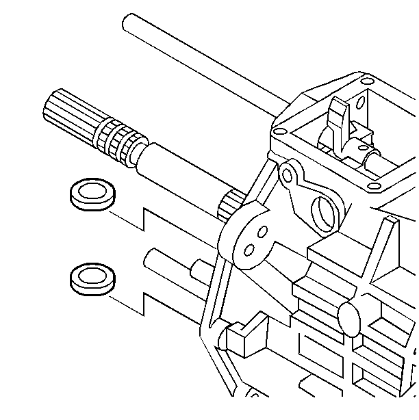
- Remove the magnets from the transmission case.
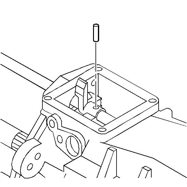
- Remove the offset lever roll pin.
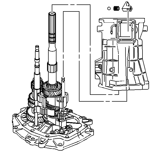
- Remove the transmission case and the offset lever together as follows:
| 13.1. | Slide the transmission case up and off of the gear clusters and the shift shaft components. |
| 13.2. | Hold the offset lever against the guide plate in order to prevent the release of the detent ball and the spring. |
| 13.3. | Remove the offset lever from the transmission case. |
Guide Plate Removal

- Remove the detent guide plate attaching bolts.
- Remove the detent guide plate.
Reverse Lockout Assembly Disassemble
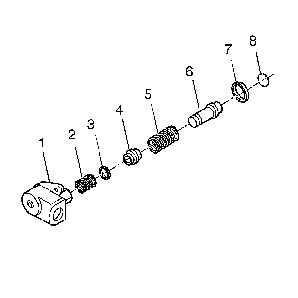
Caution: The reverse lockout assembly is under spring pressure. Exercise caution
when removing the retainer ring, as bodily injury may result.
- Remove the O-ring (8) from the body (1).
- Remove the retainer ring (7) from the body (1).
- Remove the reverse lockout inner spring (2).
- Compress the reverse lockout plunger (6) and the collar (4) in
a vise and remove the retainer ring (3).
- Remove the reverse lockout plunger (6).
- Remove the reverse lockout outer spring (5).
- Remove the reverse lockout collar (4).
Shift Shaft Assemblies and Gear Cluster Removal

- Rotate the 5th/6th and the reverse shift shaft
levers off the shift interlock plate.
- Remove the 5th/6th and the reverse shift shaft assembly.

- Remove the countershaft. Lift up the mainshaft
enough in order to remove the countershaft.

- Remove the mainshaft and the shift shaft components
as an assembly.
Important: When removing the shift shaft be careful not to lose the dowel pin.
- Remove the shift shaft assembly from the mainshaft.

- Remove the input shaft.
Transmission Disassemble Corvette Z06
Extension Housing Removal
Tools Required
| • | J 44395
Transmission Holding Fixture |

- Remove the auxiliary coolant pump bolt (2) (MY6 only).
- Remove the auxiliary coolant pump (1) (MY6 only).

- Remove the adapter plate bolts (1) and (2).

- Install the
J 44395
.
- Mount the transmission on a workbench using the
J 3289-20
.
- Rotate the transmission into a horizontal position.
- Remove the transmission drain plug and drain the transmission fluid.
- Shift the transmission into neutral (N).

- Remove the rear extension housing bolts and the rear extension housing.
Reverse Speed Gear Removal
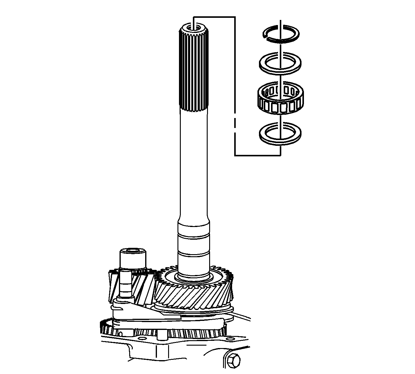
- Remove the rear bearing retainer ring.
- Remove the spacer.
- Remove the mainshaft rear roller bearing.
- Remove the spacer.
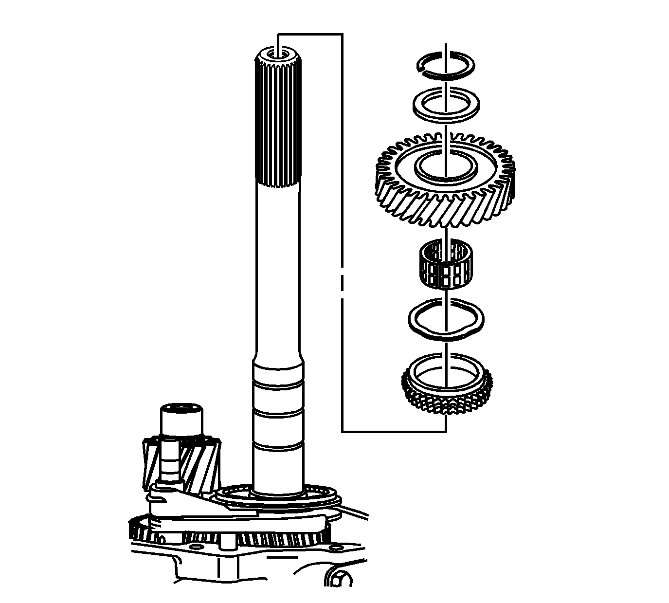
- Remove the retainer ring.
- Remove the reverse gear thrust washer.
- Remove the reverse gear.
- Remove the reverse gear caged needle bearing.
- Remove the wave washer.
- Remove the reverse gear synchronizer blocking ring.
Reverse Shift Fork Removal
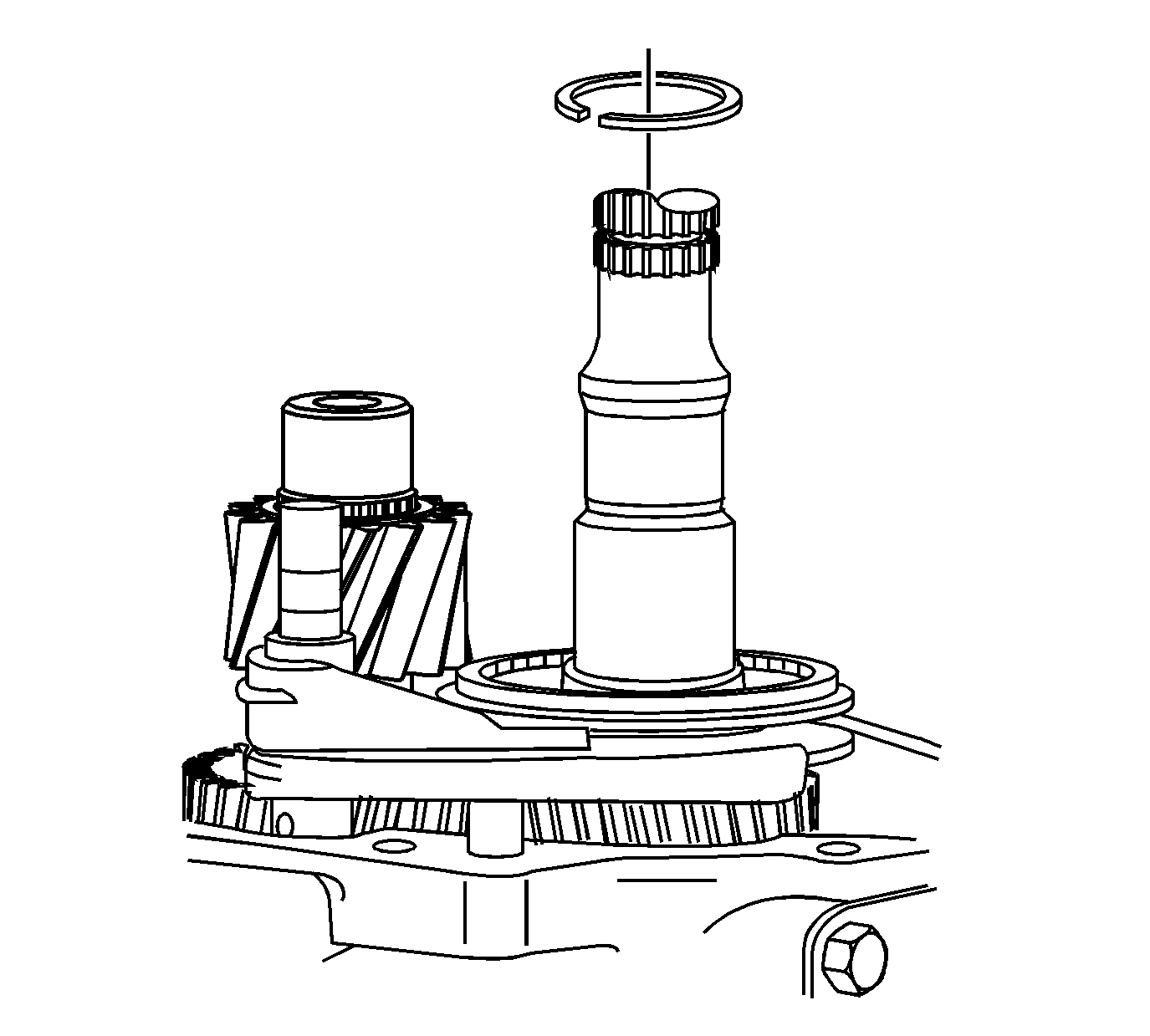
- Remove the reverse synchronizer retainer ring.
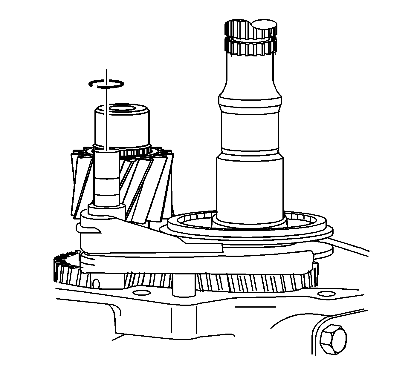
- Remove and discard the reverse shift fork retainer ring.

- Scribe a mark on the synchronizer hub and on the sleeve. This will help you to reinstall the parts in the same
position.
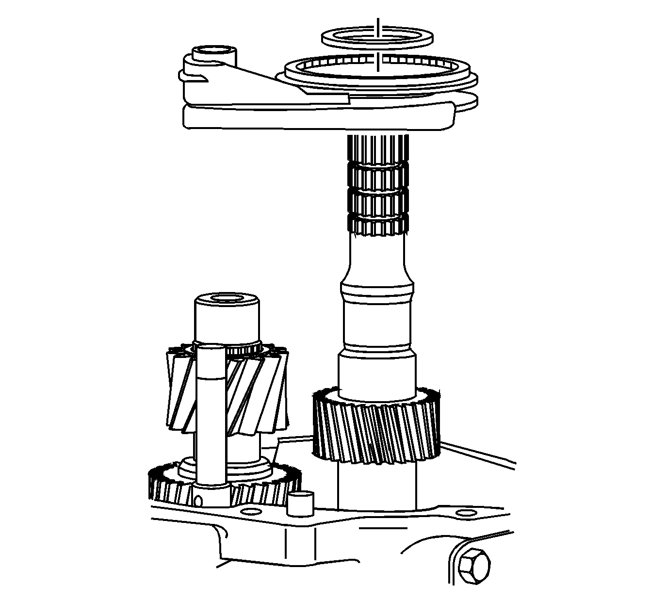
- Remove the following parts in order:
| 4.2. | The reverse synchronizer assembly and the shift fork |
5th/6th Speed Driven Gear Removal
Tools Required
| • | J 8433
Universal Bridge Puller |
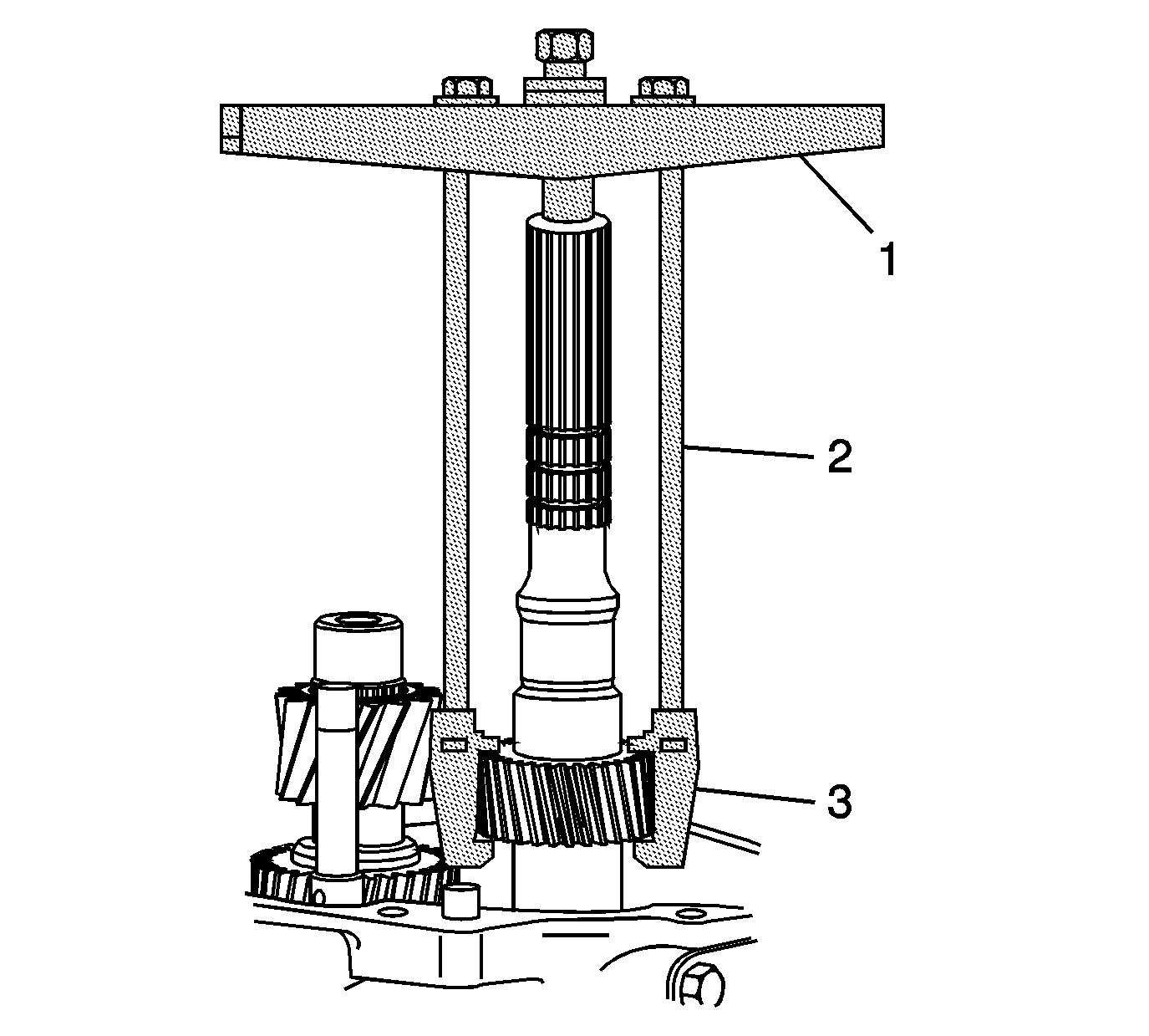
Remove the 5th/6th speed driven gear. Use the
J 8433
(1) , the
J 39431
(3) and the J 39431-4 (2).
Countershaft Gear Removal
Tools Required
J 25031-A
Three Jaw Puller
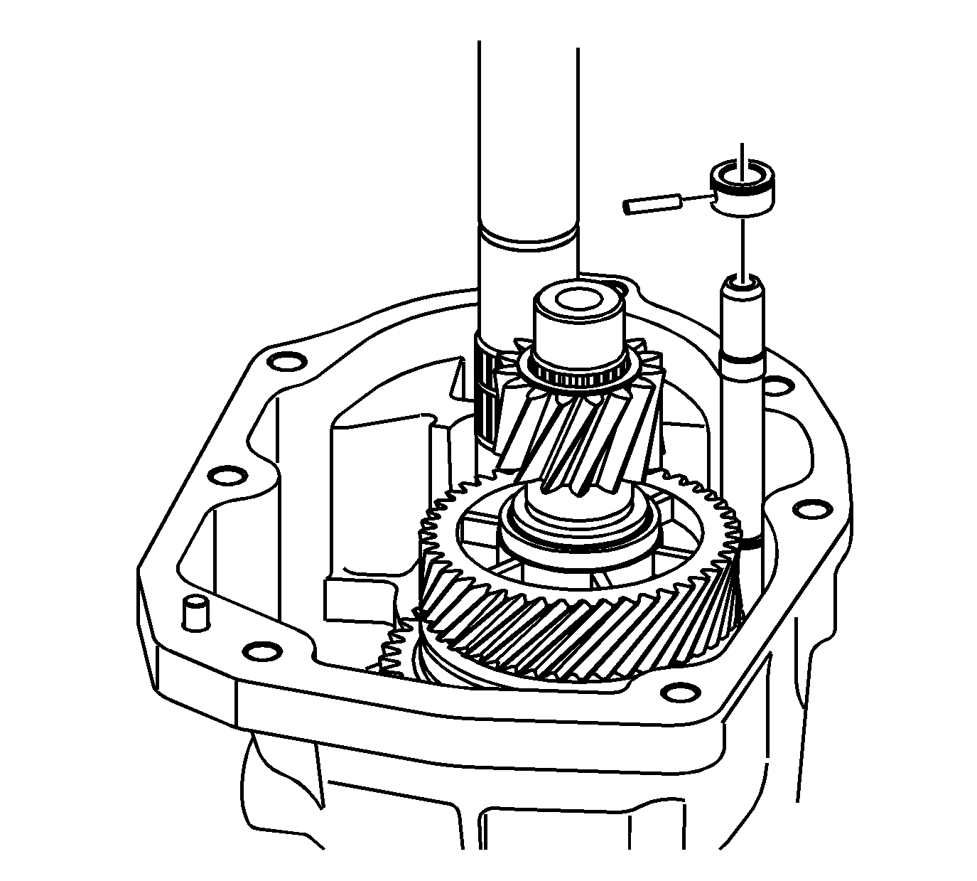
- Remove the reverse shift shaft pin and collar. Remove the countershaft retainer clip.
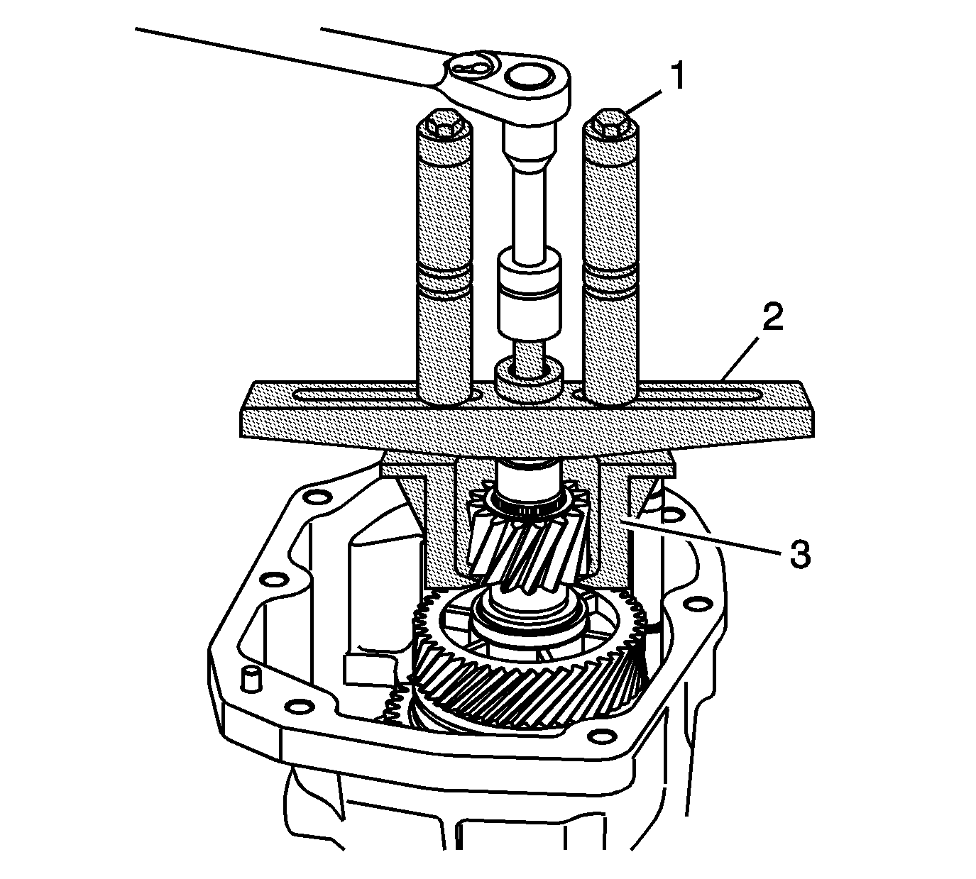
- Attach the
J 8433
(2) , the
J 39431
(3) and the J 39431-4 (1).
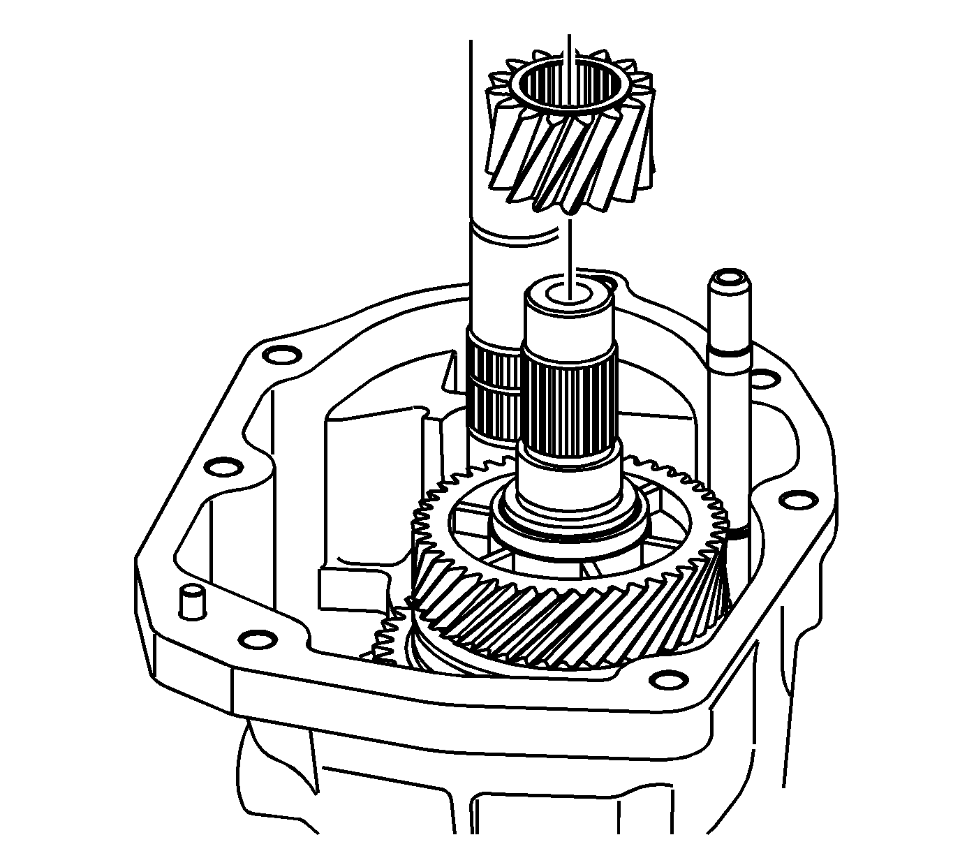
- Remove the countershaft gear.
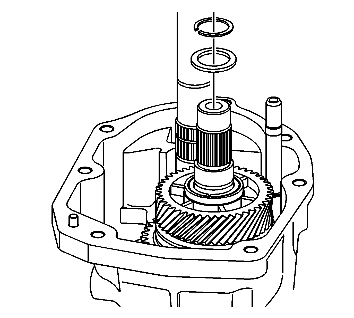
- Remove the countershaft retainer and spacer.
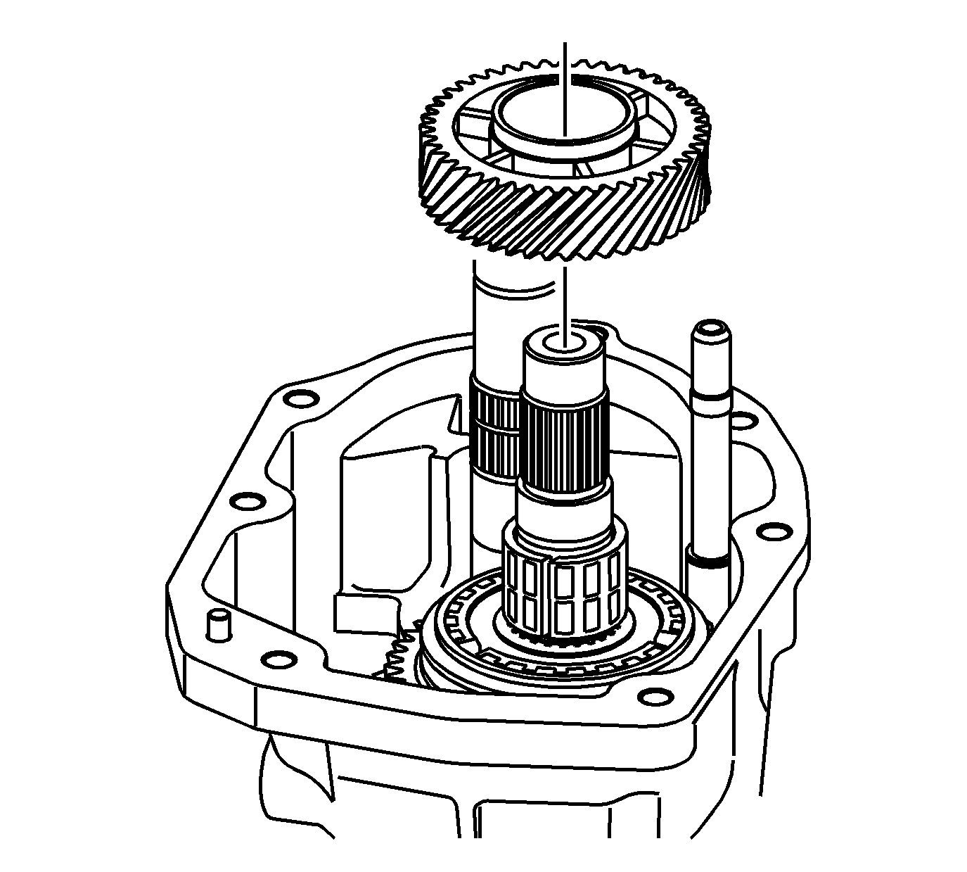
- Remove the gear from the countershaft.
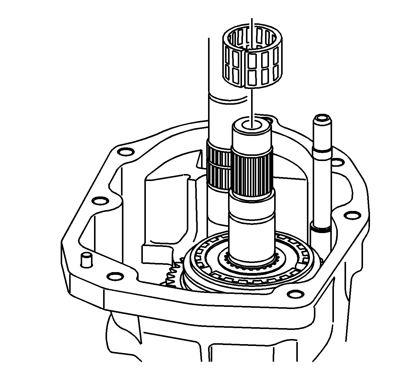
- Remove the needle bearing from the countershaft.
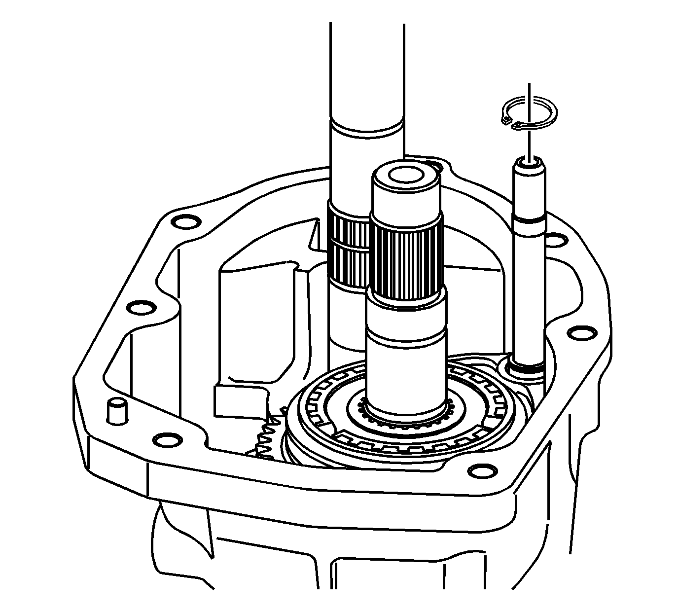
- Remove the 5th/6th speed shift fork retainer ring.
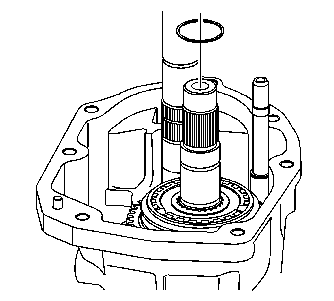
- Remove the spacer from the countershaft.
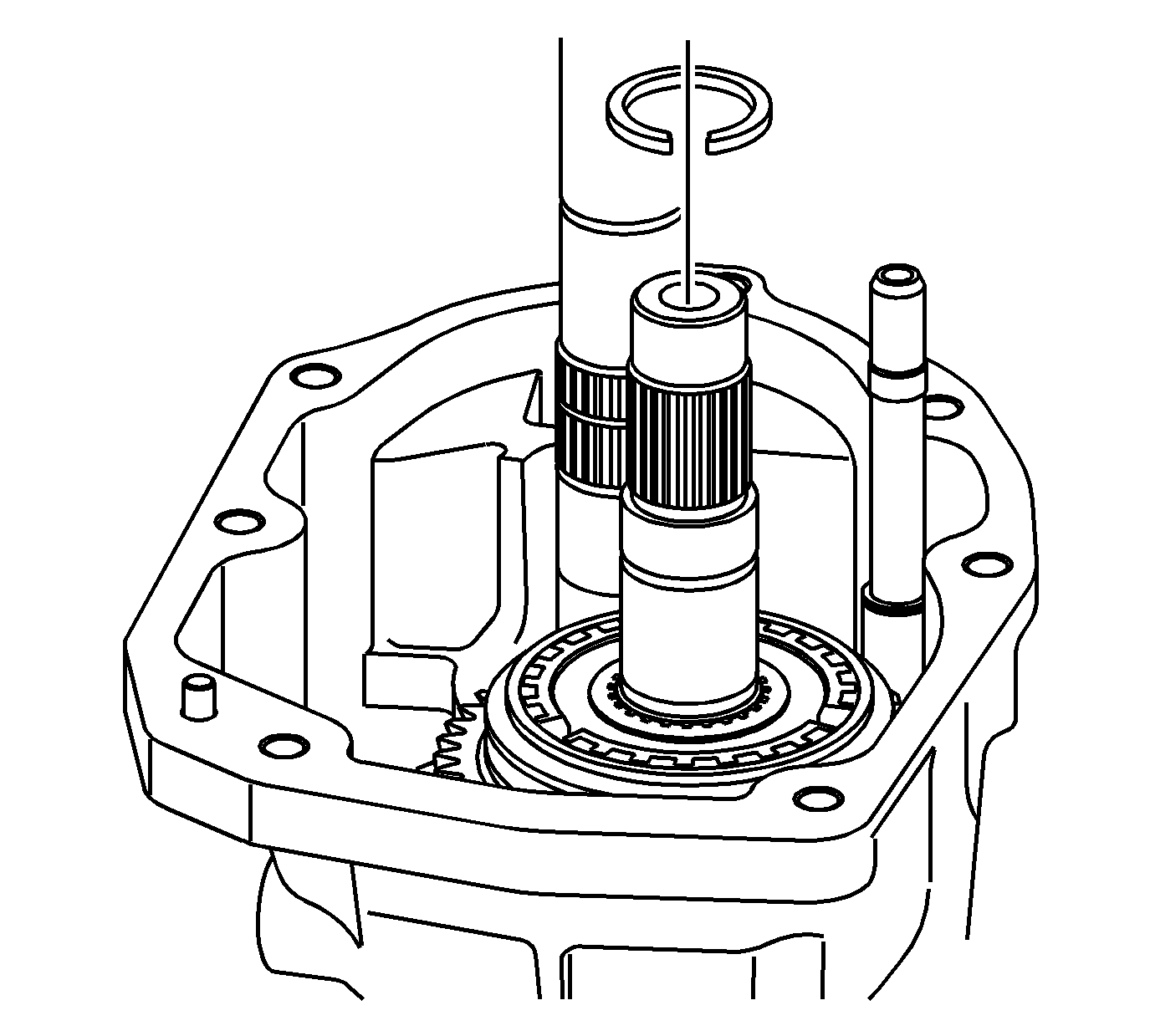
- Remove the retainer clip from the countershaft.
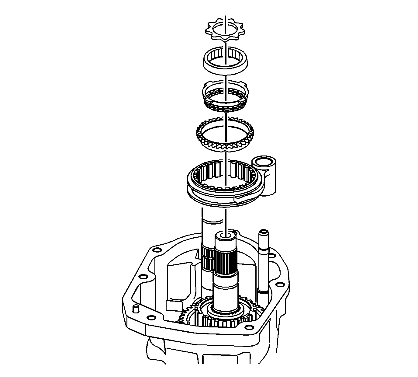
- Remove the 5th/6th shift fork, synchronizer sleeve, speed drive gear synchronizer blocking ring, speed drive
gear friction cone, speed drive gear inner cone, speed drive gear thrust washer.
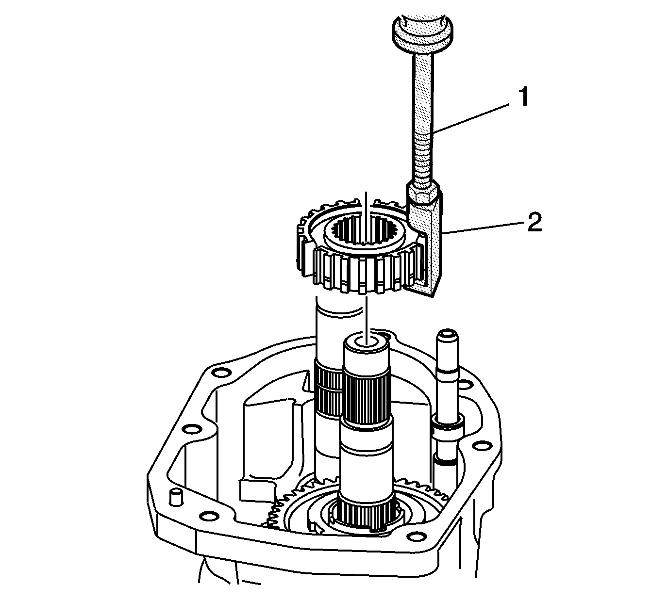
- Install the
DT-49139
between the synchronizer hub
assembly and synchronizer blocking ring.
- Remove the synchronizer hub assembly with
J 6125-1B
.
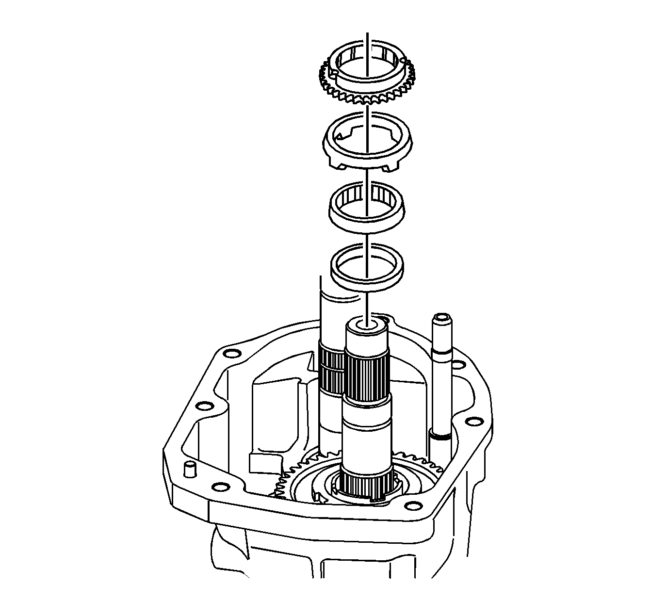
- Remove the 5th/6th shift fork, synchronizer sleeve, speed drive gear synchronizer
blocking ring, speed drive gear friction cone, speed drive gear inner cone, speed drive gear thrust washer.
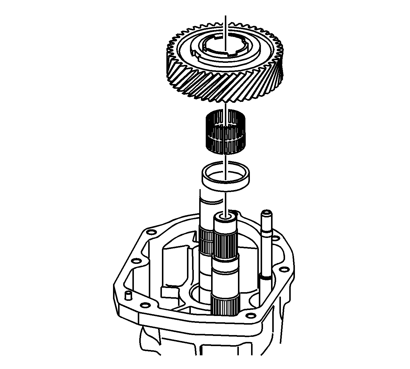
- Remove the 6th driven gear, caged needle bearing, and spacer.
Transmission Case Removal
Tools Required
J 41099
Skip Shift Sensor Remover/ Installer

- Remove the computer aided gear select solenoid.

- Remove the reverse lockout solenoid from the reverse lockout body. Use the
J 41099
.

- Remove the reverse lockout assembly bolt and the reverse lockout body.

- Remove the shifter cover plate retainer bolts.
- Remove the shifter cover plate.

- Remove the shift detent assembly.

- Remove 9 of the 11 adapter plate to transmission case bolts.
- Rotate the transmission into the vertical position.

- Remove the last 2 adapter plate to transmission case bolts.
- Remove the shift lever guide bolts.

- Remove the magnets from the transmission case.

- Remove the offset lever roll pin by using a punch to push the pin through the shift shaft.
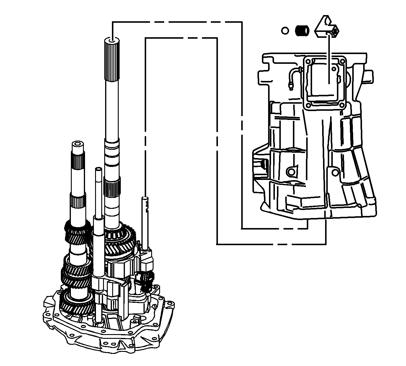
- Remove the transmission case and the offset lever together as follows:
| 13.1. | Slide the transmission case up and off of the gear clusters and the shift shaft components. |
| 13.2. | Hold the offset lever against the guide plate in order to prevent the release of the detent ball and the spring. |
| 13.3. | Remove the offset lever from the transmission case. |
Guide Plate Removal

- Remove the detent guide plate attaching bolts.
- Remove the detent guide plate.
Reverse Lockout Assembly Disassemble

Caution: The reverse lockout assembly is under spring pressure. Exercise caution
when removing the retainer ring, as bodily injury may result.
- Remove the O-ring (8) from the body (1).
- Remove the retainer ring (7) from the body (1).
- Remove the reverse lockout inner spring (2).
- Compress the reverse lockout plunger (6) and the collar (4) in a vise and remove the retainer ring (3).
- Remove the reverse lockout plunger (6).
- Remove the reverse lockout outer spring (5).
- Remove the reverse lockout collar (4).
Shift Shaft Assemblies and Gear Cluster Removal
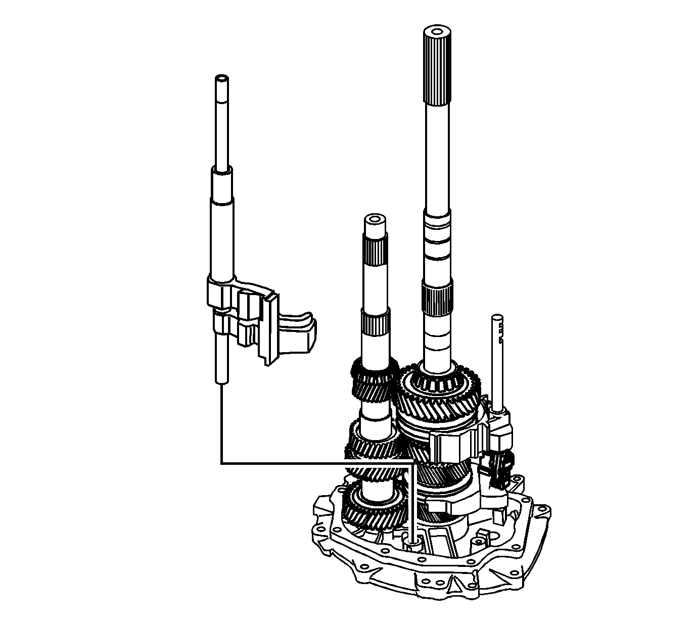
- Rotate the 5th/6th and the reverse shift shaft levers off the shift interlock plate.
- Remove the 5th/6th and the reverse shift shaft assembly.
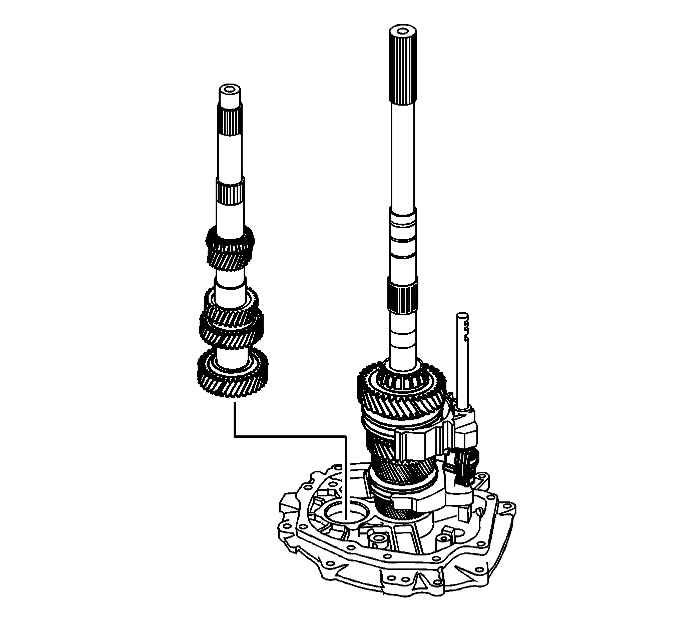
- Remove the countershaft. Lift up the mainshaft enough in order to remove the countershaft.

- Remove the mainshaft and the shift shaft components as an assembly.
Important: When removing the shift shaft be careful not to lose the dowel pin.
- Remove the shift shaft assembly from the mainshaft.

- Remove the input shaft.
Transmission Disassemble SSR M10
Extension Housing Removal
Tools Required
| • | J 39430
Transmission Holding Fixture |

- Remove the adapter plate bolts (1) and (2).

- Install the
J 39430
(2).
- Mount the transmission on a workbench using the
J 3289-20
(1).
- Rotate the transmission into a horizontal position.
- Remove the transmission drain plug and drain the transmission fluid.
- Shift the transmission into NEUTRAL (N).

- Remove the shifter cover plate bolts.
- Remove the shifter cover plate.

- Remove the propshaft connector bolt.
- Remove the propshaft.

- Remove the rear extension housing bolts and the rear extension housing.
Reverse Speed Gear Removal

- Remove the shift guide rollpins.
- Remove the shift guide.
- Remove the shift shaft extension.

- Remove the following parts in order:

- Remove the rear bearing retainer ring.
- Remove the spacer.
- Remove the mainshaft rear roller bearing.
- Remove the spacer.

- Remove the retainer ring.
- Remove the reverse gear thrust washer.
- Remove the reverse gear.
- Remove the reverse gear caged needle bearing.
- Remove the wave washer.
- Remove the reverse gear synchronizer blocking ring.
Reverse Shift Fork Removal

- Remove the reverse synchronizer retainer ring.

- Remove and discard the reverse shift fork retainer ring.

- Scribe a mark on the synchronizer hub and on the sleeve. This will help you to reinstall the parts in the same
position.

- Remove the following parts in order:
| 4.2. | The reverse synchronizer assembly and the shift fork |
5th/6th Speed Driven Gear Removal
Tools Required
| • | J 8433
Universal Bridge Puller |

Remove the 5th/6th speed driven gear. Use the
J 8433
, the
J 39431
and the J 39431-4.
Countershaft Gear Removal
Tools Required
J 25031-A
Three Jaw Puller

- Remove the reverse shift shaft pin and collar. Remove the countershaft retainer clip.

- Attach the
J 8433
(2) , the
J 39431
(3) and the J 39431-4 (1).

- Remove the countershaft gear.

- Remove the countershaft retainer and spacer.

- Remove the gear from the countershaft.

- Remove the needle bearing from the countershaft.

- Remove the 5th/6th speed shift fork retainer ring.

- Remove the spacer from the countershaft.

- Remove the retainer clip from the countershaft.

- Remove the 5th/6th shift fork, synchronizer sleeve, speed drive gear synchronizer blocking ring, speed drive
gear friction cone, speed drive gear inner cone, speed drive gear thrust washer.
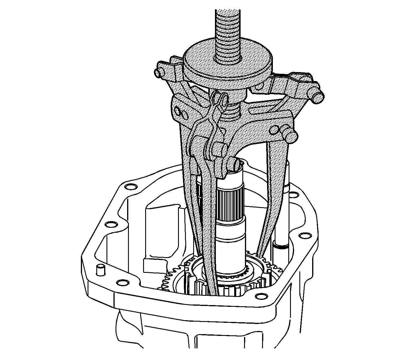
- Install the
J 25031-A
to the synchronizer hub assembly.
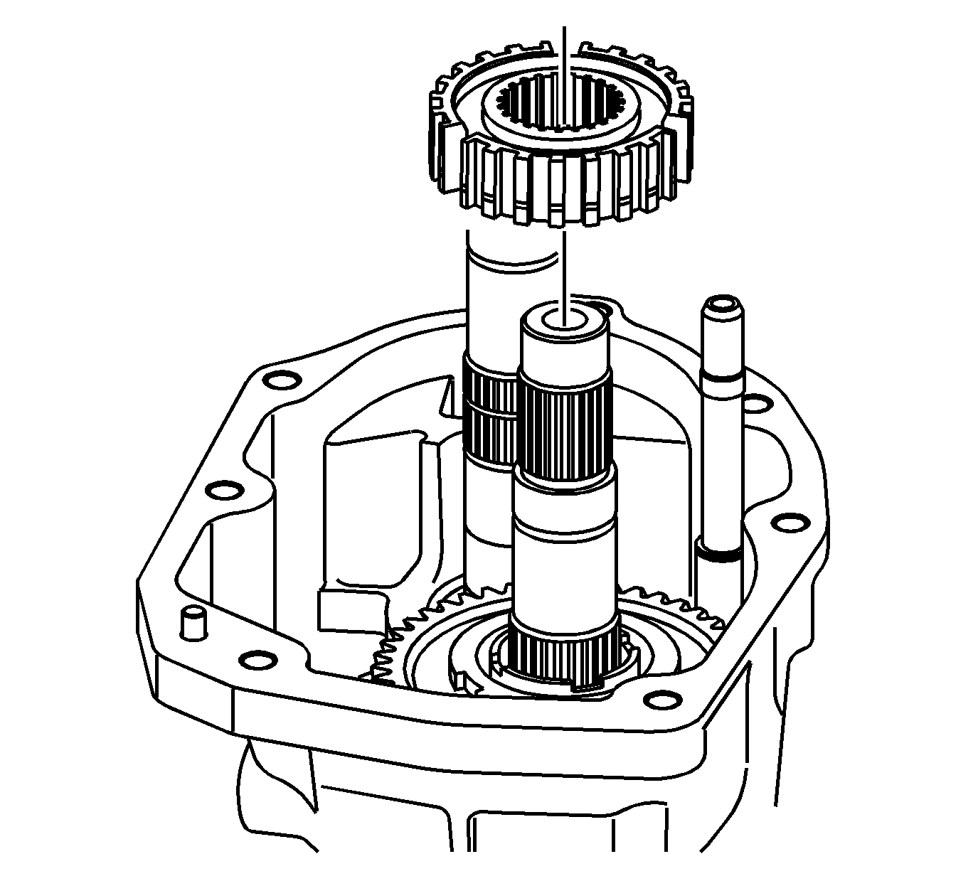
- Remove the synchronizer hub assembly.

- Remove the 5th/6th shift fork, synchronizer sleeve, speed drive gear synchronizer
blocking ring, speed drive gear friction cone, speed drive gear inner cone, speed drive gear thrust washer.

- Remove the 6th driven gear, caged needle bearing, and spacer.
Transmission Case Removal
Tools Required
J 41099
Skip Shift Sensor Remover/ Installer

- Remove the computer aided gear select solenoid.

- Remove the shift detent assembly.

- Remove the shift detent plug, spring, and ball.

- Remove 9 of the 11 adapter plate to transmission case bolts.
- Rotate the transmission into the vertical position.

- Remove the last 2 adapter plate to transmission case bolts.
- Remove the shift lever guide bolts.

- Remove the magnets from the transmission case.
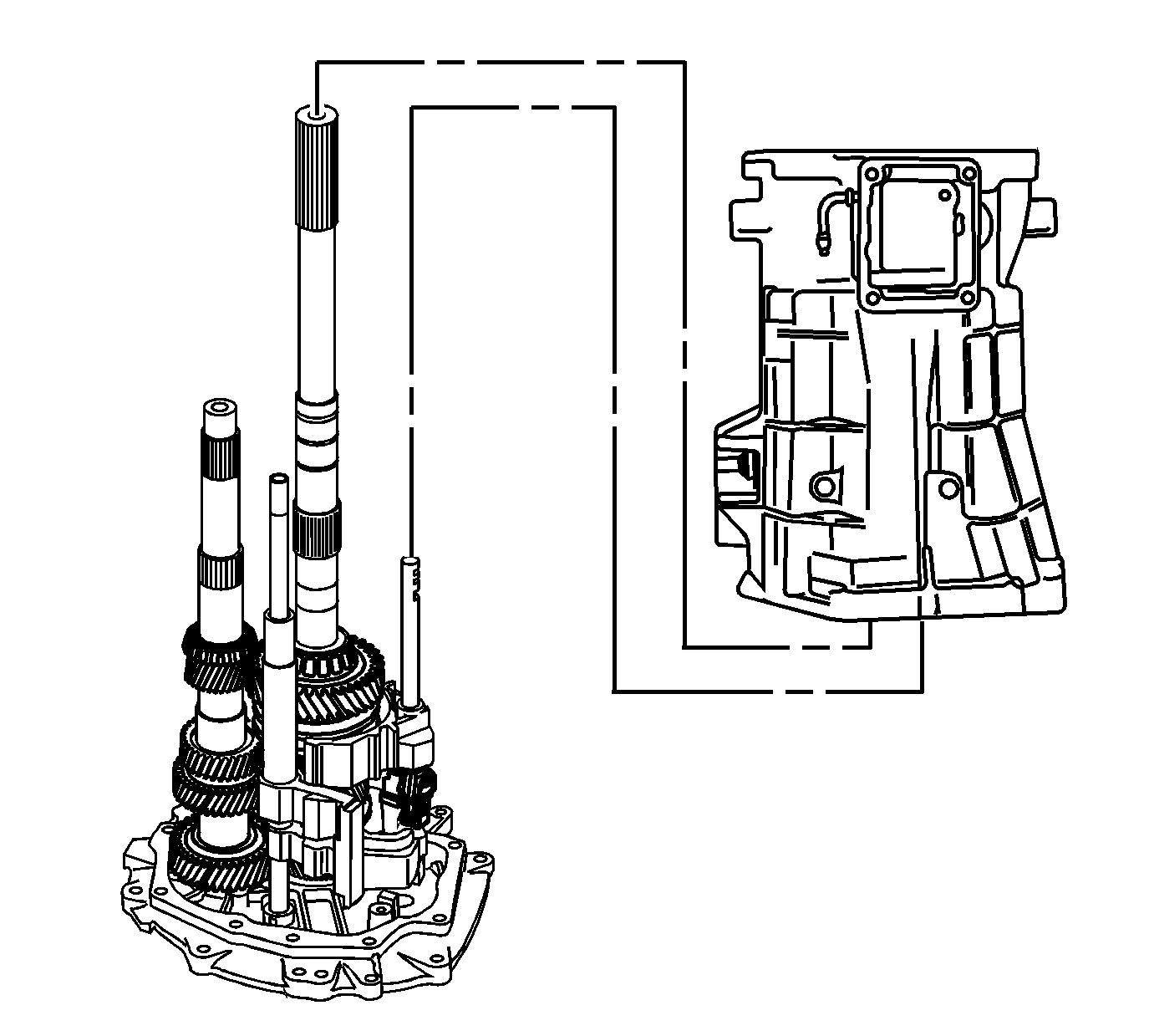
- Remove the transmission case and the offset lever together as follows:
| 9.1. | Slide the transmission case up and off of the gear clusters and the shift shaft components. |
| 9.2. | Hold the offset lever against the guide plate in order to prevent the release of the detent ball and the spring. |
| 9.3. | Remove the offset lever from the transmission case. |
Guide Plate Removal

- Remove the detent guide plate attaching bolts.
- Remove the detent guide plate.
Shift Shaft Assemblies and Gear Cluster Removal

- Rotate the 5th/6th and the reverse shift shaft levers off the shift interlock plate.
- Remove the 5th/6th and the reverse shift shaft assembly.

- Remove the countershaft. Lift up the mainshaft enough in order to remove the countershaft.

- Remove the mainshaft and the shift shaft components as an assembly.
Important: When removing the shift shaft be careful not to lose the dowel pin.
- Remove the shift shaft assembly from the mainshaft.

- Remove the input shaft.


