CAMPAIGN:FUEL FEED AND RETURN HOSE/PIPE ASSEMBLIES

MODELS AFFECTED: Certain 1987 Grand Am Models With 2.5L L68 (VIN Code U) Engines and MT2 Five- Speed Manual Transaxles
The National Traffic and Motor Vehicle Safety Act, as amended, provides that each vehicle which is subject to a recall campaign of this type, must be adequately repaired within a reasonable time after the owner has tendered it for repair. A failure to adequately repair within sixty days after tender of a vehicle is prima facie evidence of failure to repair within a reasonable time.
If the condition is not adequately repaired within a reasonable time the owner may be entitled to an identical or reasonable equivalent vehicle at no charge or to a refund of the purchase price, less a reasonable allowance for depreciation.
To avoid having to provide these burdensome solutions, every effort must be made to promptly schedule an appointment with each owner and to repair their vehicle as soon as possible. As you will see in reading the attached copy of the letter which is being sent to owners, the owners are being instructed to contact the Pontiac Customer Assistance Center if their dealer does not remedy the condition within five days of the mutually agreed upon service date. If the condition is not remedied within a reasonable time, owners are instructed on how to contact the National Highway Traffic Safety Administration.
CONDITION INVOLVED
General Motors has determined that a defect which relates to motor vehicle safety may exist in some 1987 Grand Am models equipped with 2.5L engines and five-speed manual transaxles. The fuel feed or fuel return hose at the engine may rub against a shift lever on the 5-speed transaxle. With time, a hole could be rubbed through the hose and fuel could leak into the engine compartment. Under certain circumstances, this could result in an underhood fire.
DEALER ACTION
To prevent the possibility of the aforementioned condition occurring on the vehicles involved, dealers are to replace the Fuel Feed and Return Hose Pipe Assemblies in accordance with the Vehicles Involved and Service Procedure section of this bulletin.
VEHICLES INVOLVED
Involved are certain Pontiac Grand Am models equipped with 2.5L L68 (VIN Code U) engines and MT2 Five-speed Manual Transaxles within the following VIN breakpoints:
Model/Year Plant Beginning Up to and Including ---------- ----- --------- ------------------- Grand AM/1987 Lansing HC700001 HC917871
Involved vehicles have been identified by Vehicle Identification Number computer listings. Computer listings contain the complete Vehicle Identification Number, owner name and address data, and are furnished to the involved dealers with the campaign bulletin. Owner name and address data furnished will enable dealers to follow up with owners involved in this campaign.
These listings may contain owner names and addresses obtained from State Motor Vehicle Registration Records. The use of such motor vehicle registration data for any other purpose is a violation of law in several states. Accordingly, you are urged to limit the use of this listing to the follow up necessary to complete this campaign. Any dealer not receiving a computer listing with the campaign bulletin has no involved vehicles currently assigned.
OWNER NOTIFICATION
Owners will be notified of this campaign on their vehicles by Pontiac Division (see copy of Owner Letter included with this bulletin).
DEALER CAMPAIGN RESPONSIBILITY
Dealers are to service all vehicles subject to this campaign at no charge to owners, regardless of mileage, age of vehicle, or ownership from this time forward.
Whenever a vehicle subject to this campaign is taken into your new or used vehicle inventory, or it is in your dealership for service in the future, you should take the steps necessary to be sure the campaign correction has been made before reselling or releasing the vehicle.
Owners of vehicles recently sold from your new vehicle inventory are to be contacted by the dealer, and arrangements made to make the required modification according to instructions contained in this bulletin.
PARTS INFORMATION
Parts required to complete this campaign are to be obtained from General Motors Service Parts Operation (GMSPO). To insure that these parts are obtained as soon as possible they should be ordered on a C.I.O. order with no special instruction code, but on advise code (2).
Description Part Number Quantity Per Vehicle ----------- ----------- -------------------- Hose - Fuel Feed Front 10101301 1
Hose - Fuel Return Front 10101315 1
Seal, Fuel Feed Pipe 22514722 Max. 2, As Required (0-Ring)
Seal, Fuel Return Pipe 22516256 Max. 2, As Required (0-Ring)
SERVICE PROCEDURE
1. Place car on hoist. Open and prop hood. Install fender covers on both fenders.
2. CAUTION: To reduce the risk of fire and personal injury, it is necessary to relieve fuel system pressure before servicing fuel system components. To do this:
- Remove "Fuel Pump" fuse (25 amp. at position # 12) from fuse block in passenger compartment.
- Crank engine. Engine will start and run until fuel supply remaining in fuel lines has been consumed. Engage starter for three (3) seconds to assure relief of any remaining pressure.
- Unless this procedure is followed before servicing fuel lines or connections, fuel spray could occur.
3. Disconnect negative cable at battery.
4. At air cleaner, disconnect hoses and electrical connector to Manifold Absolute Pressure (MAP) sensor. Remove air cleaner and air inlet hose.
5. Disconnect electrical connectors at Manifold Air Temperature (MAT) sensor and at lower throttle body. Move the wiring harness back toward the cowl. Do not remove the connector to the injector in the top of the throttle body.
6. Using a 19 mm extended socket, remove the MAT sensor and set aside for later reinstallation.
7. Loosen mounting bolts of power steering pump to provide clearance when the fuel lines are removed and replaced later. It is not necessary to remove the pump from the engine.
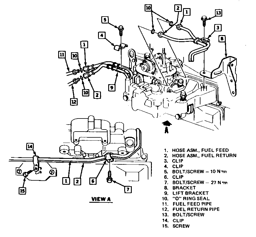
8. Unbolt clips (3) and (4) which retain the Fuel Feed and Fuel Return Hose/ Pipe Assemblies to the top side of the engine (see illustration). Save the bolts and clamps for reuse.
9. Disconnect the Fuel Feed and Fuel Return Hose/Pipe Assembly fittings at the throttle body and at the chassis lines. Refer to illustration. Use a backup wrench while loosening fittings.
10. Hoist vehicle. Unbolt clip (6) from underside of intake manifold. Unscrew clip (14) from bracket which is bolted on the push rod cover. Save clips and bolts/screws for reuse.
11. Lower vehicle.
12. Remove both the Fuel Feed and Fuel Return Hose Assemblies, moving power steering pump as required for clearance.
13. Examine the fittings on the Hose/Pipe Assemblies and the chassis pipes for missing or damaged O-rings. If O-rings need replacing, use part number indicated in the parts information section.
14. Thread new Fuel Feed Hose/Pipe Assembly (part number 10101301) from area of power steering pump under the intake manifold and over the lift bracket, (9) in illustration:
- At the lift bracket, the fuel hose must pass UNDER the spark plug wires, UNDER the wire to coolant temperature sensor, and UNDER the engine wiring harness (harness to starter and cooling fan).
- In the area under the intake manifold, the fuel pipe must pass ABOVE all hoses and wires.
- Move the power steering pump as necessary to permit connecting the fuel pipe to the throttle body fitting.
15. Repeat step 14 with the new Fuel Return Hose/Pipe Assembly (part number 10101315).
16. Install the pipe fittings to the throttle body and the chassis pipes finger tight. Do not torque at this time.
17. Loosely install clip (4) and screw (5) at lift bracket (9) as shown in the illustration.
- Loosely install clip (3) and bolt (13) as shown in the illustration.
18. Raise the vehicle and reinstall clip (6) as shown in the illustration, torque bolt (7) to 27 N.m (20 lbs. ft.).
- Reinstall clip (14) as shown in illustration, torque screw (15) securely.
19. Lower the vehicle and torque screw (5) to 10 N.m (90 lbs. in.). Torque bolt (13) securely.
20. Torque the pipe fittings at the throttle body to 27 N.m (20 lbs. ft.). Use a backup wrench.
21. Torque the hose fittings to the chassis fuel pipes at 27 N.m. (20 lbs. ft.). Use a backup wrench and take care not to twist the hoses.
22. Inspect both hose/pipe assemblies to assure the following conditions:
- They MUST clear the shift lever on the transaxle by at least 10 mm. (3/8 inch) in every gear position.
- They do not contact the transaxle Fluid LeveT Indicator.
- They do not contact the brake pipes.
The chassis fuel pipes should be vertical at the engine compartment rail.
23. Refer to the 1987 Pontiac Grand Am Chassis Service Manual and torque power steering pump mounting bolts as shown on page 3B3-3. Adjust belt tension per chart on page 3B3-2.
24. Reinstall the MAT sensor.
25. Reinstall the electrical connectors at the MAT sensor and lower throttle body.
26. Reinstall air cleaner and air inlet hose. Reinstall electrical connector to MAP and hoses to air cleaner.
27. Reconnect negative cable at battery.
28. Reinstall the "Fuel Pump" fuse.
29. Start the engine and check the fuel hose/pipe fittings at the chassis lines and the throttle body for leaks.
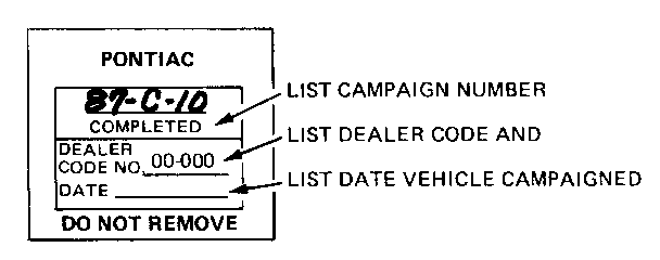
30. Turn off engine and install a campaign label.
31. Remove fender covers and close hood.
CAMPAIGN IDENTIFICATION LABEL (Figure 1)
Each vehicle modified in accordance with the instructions outlined in this Product Campaign Bulletin will require a "Campaign Identification Label." Each label provides a space to include the campaign number, the five digit dealer code of the dealer performing the campaign service, and the date the vehicle was campaigned. This information may be inserted with a typewriter or ball point pen. Install the label only on a clean, dry surface of the radiator baffle where it is readily visible. (Additional campaign labels are available on stationery order as Form 7901-709).
CLAIM INFORMATION
A separate repair order must be used for each vehicle. A completed warranty claim is to be kept as a permanent record of completion.
DEALERS SHOULD SUBMIT WARRANTY CLAIMS FOR CREDIT IN THEIR NORMAL MANNER WHEN THEY PERFORM THE SERVICE AS FOLLOWS:
Other * Failure Labor Labor Labor Operation Code Operation Hours Hours --------- ---- --------- ----- ----- Replace Fuel Feed and Return Hose/Pipe Assembly 96 V4500 1.0 .1
* In addition dealerships will receive 0.1 hours credit for dealer administrative services associated with this campaign. The 0.1 hours allowance is to be entered in the "Other Labor Hours" field with each campaign repair listed for credit. This entry will not require authorization.
FAILURE CODE 96 MUST BE USED WITH THE LABOR OPERATION.
Parts required are to be listed in your warranty claim in the normal manner. Parts will be credited at dealer net plus 30% dealer handling allowance.
Dealers will be credited via Warranty Document or Terminal Transmission, whichever is their normal method of submission for payment. Claim must contain all information required and should list the labor operation as outlined.
RECORDING COMPLETION
Repairs submitted for vehicles not involved in the campaign will not be paid.
Campaign completion will be recorded from "PROPERLY COMPLETED AND PAID WARRANTY CLAIMS." Owners are being asked to present the owner reply card for identification to their dealer at the time they bring in their vehicle to have the campaign performed.


General Motors bulletins are intended for use by professional technicians, not a "do-it-yourselfer". They are written to inform those technicians of conditions that may occur on some vehicles, or to provide information that could assist in the proper service of a vehicle. Properly trained technicians have the equipment, tools, safety instructions and know-how to do a job properly and safely. If a condition is described, do not assume that the bulletin applies to your vehicle, or that your vehicle will have that condition. See a General Motors dealer servicing your brand of General Motors vehicle for information on whether your vehicle may benefit from the information.
