UPDATE-MISSING SCHEMATIC DIAGNOSTIC/REVISED PAGES

Models Affected: 1988 GRAND AM
The UW4 speaker and amplifier system available on the 1988 Pontiac Grand Am was omitted from Section 8A-150 of the service manual. Please add/replace the following pages to your copy of the service manual.
Old Pages New Pages --------- --------- Year Service Manual Remove Add ---- -------------- ------ --- 1988 Pontiac Grand Am 8A-150-OA 8A-150-OB 8A-150-1 8A-150-1 8A-150-2 8A-150-2 8A-150-4A 8A-150-4B 8A-150-5 8A-150-5
Note: If a component location Page-Figure reference is not given, see the 1989 Grand AM Service Manual for component location Page-Figure references.
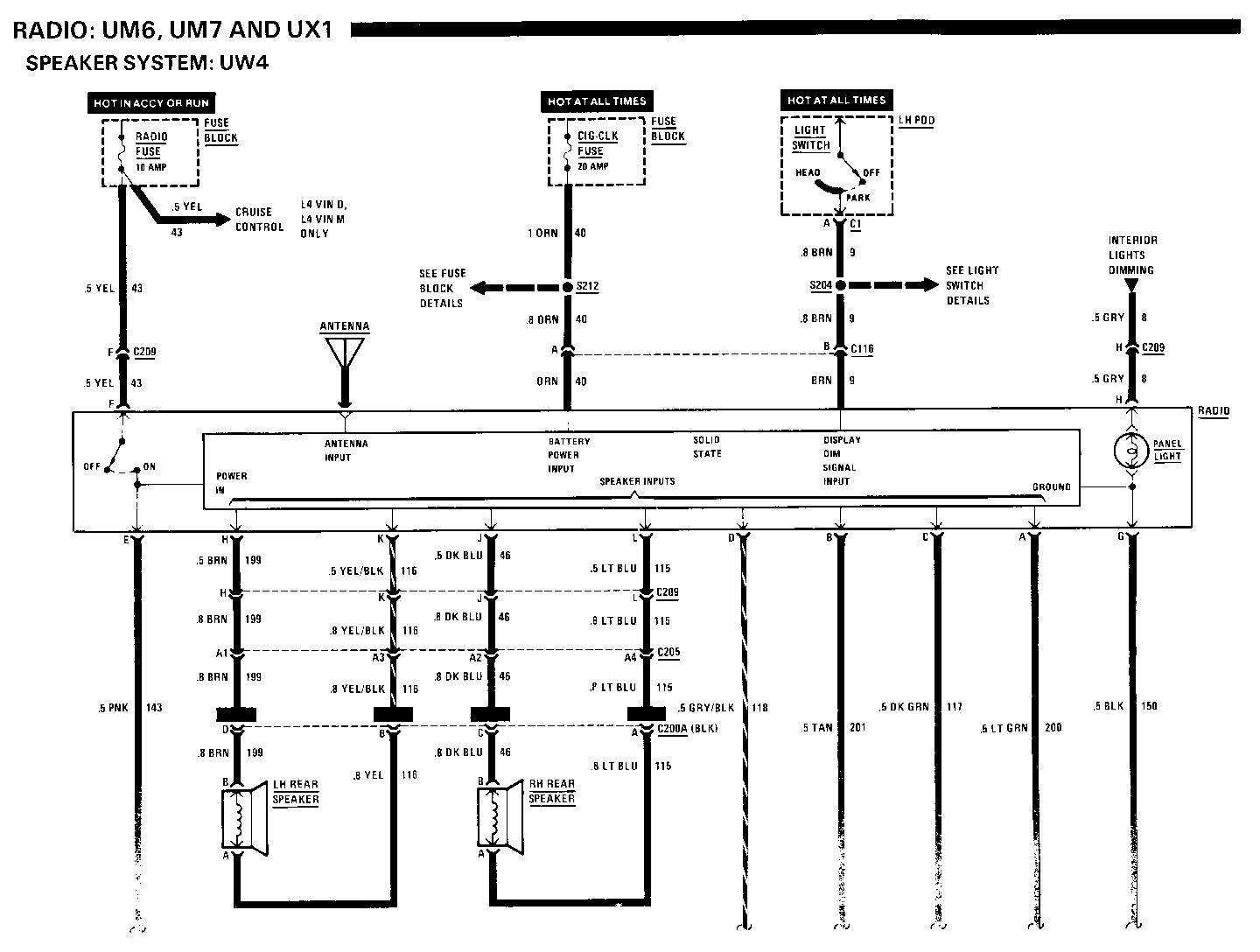
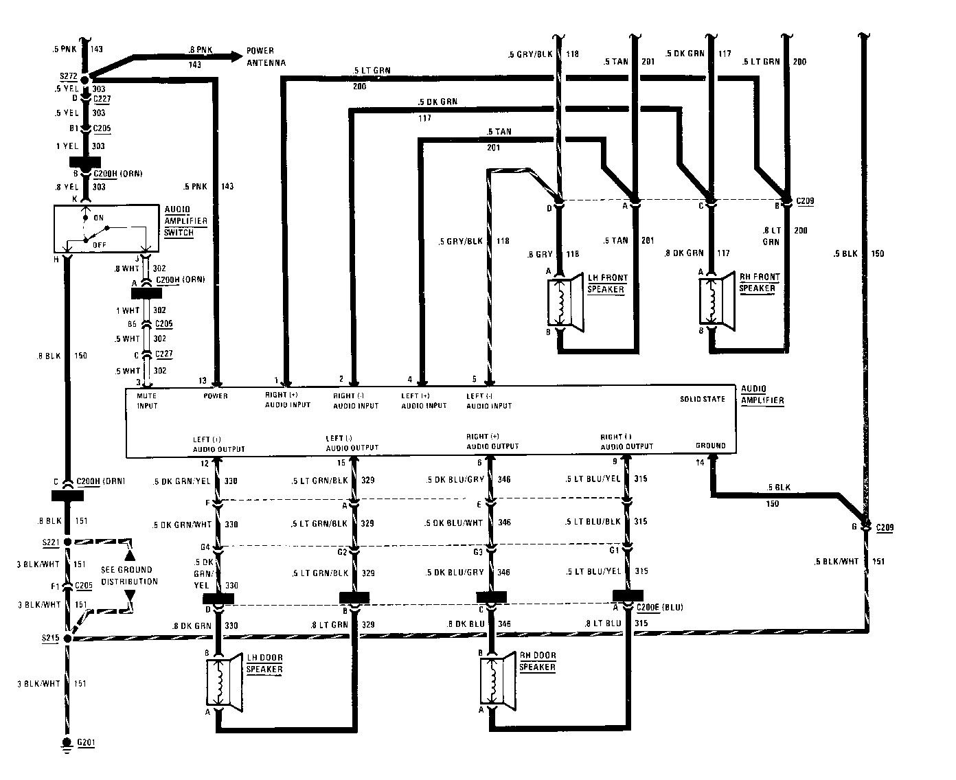
COMPONENT LOCATION Page-Figure ------------------ ----------- Audio Amplifier......Underneath front of console.................. Fuse Block...........Under LH side of I/P.........................201- 9-A C200 (39 cavities)...In console, behind gear selector.............201-10-D C205 (30 cavities)...Behind center of I/P, beneath radio..........201-10-D C209 (12 cavities)...Behind center of I/P, near radio............. C227 (6 cavities) ...Center of I/P, behind radio.................. G201 ................Behind I/P, near bottom of steering column...201- 8-A S204 ................I/P harness, behind center of I/P............201- 8-A S212 ................I/P harness, RH side of I/P..................201- 8-A S215 ................I/P harness, behind radio....................201-10-D S221 ................Console harness, forward of shifter.......... S254 ................Radio speaker harness, behind radio.......... S272 ................Radio speaker harness, behind radio..........
TROUBLESHOOTING HINTS
Try the following checks before doing the System Check.
1. Check the RADIO Fuse.
2. Check the CIG-CLK Fuse by operating the Cigar Lighter.
3. Check that the Antenna connector and coaxial cable are properly connected.
4. Adjusting Radio controls will change the operation of the sound system. Consult the Delco Sound Service Guide for information regarding the operation of these controls.
5. Before troubleshooting a suspect Speaker, check all connections to that Speaker.
6. For proper noise diagnosis, take the car out-side where signals are strong. Close hood, and keep away from metal buildings or sources of radio interference.
7. Ignition noise on FM may indicate a defective Ignition System.
8. Coated screws or bolts can cause a poor ground connection. Scrape ground screws or bolts clean of any paint or varnish.
Go to System Check for a guide to normal operation.
Go to System Diagnosis for diagnostic tests.
SYSTEM CHECK
Use the System Check Table as a guide to normal operation. Refer to System Diagnosis for a list of symptoms and diagnostic steps.
SYSTEM CHECK TABLE
ACTION NORMAL RESULT ------- ------------- With Ignition The display comes on Switch in RUN, turn
the Radio on The Digital Clock operates
Sound comes from all four Speakers
Turn Light Switch The Panel Light comes on to PARK
The Digital Display dims
Operate Radio Consult Section 9A controls
SYSTEM DIAGNOSIS
Do the tests listed for your symptom in the Symptom Table below.
Tests follow the Symptom Table.
SYMPTOM TABLE
SYMPTOM DO TEST ------- ------- Radio does not A: Radio Power appear to work (no Input Test display lights, no sound)
Panel Light does not B: Panel Light Test come
Display Dimming C: Display Dimming function does not Test operate
No sound or D: Speaker Test distorted sound comes from a speaker
Excessive noise E: Noise Diagnosis comes from all Test speakers
The LH and RH F: Audio Amplifier Door Speakers do Voltage Test not operate (with Audio Amplifier)
The LH or RH Door H: Audio Input Test Speaker does not operate (with Audio Amplifier)
A: RADIO POWER INPUT TEST (TABLE 1)
Measure:VOLTAGE
At: RADIO CONNECTOR (Disconnected)
Condition:
Ignition Switch: RUN
Measure Correct For Diagnosis Between Voltage ------------- ------- ------- F (YEL) & Battery See 1 Ground F (YEL) & G Battery See 2 (BLK)
If voltages are correct, go to Table 2.
1. Check YEL (43) wire for an open (see schematic).
2. Check BLK (150) wire for an open to ground (see schematic).
A: RADIO POWER INPUT TEST (TABLE 2)
Measure: VOLTAGE
At: RADIO CONNECTOR C116 (Disconnected)
Measure Correct For Diagnosis Between Voltage ------------- ------- ------- A (ORN) & Battery See 1 Ground
If voltage is correct, remove Radio for service.
1. Check ORN (40) wire for an open (see schematic).
B: PANEL LIGHT TEST
Measure: VOLTAGE
At: RADIO CONNECTOR (Disconnected)
Conditions:
Light Switch: PARK
Dimming Switch: BRIGHT
Measure Correct For Diagnosis Between Voltage ------------- ------- ------- H (GRY) & Battery See 1 Ground
If voltage is correct, remove Radio for service.
1. Check GRY (8) wire for an open (see schematic).
C: DISPLAY DIMMING TEST
Measure: VOLTAGE
At: RADIO CONNECTOR C116 (Disconnected)
Condition:
Light Switch: HEAD or PARK
Measure Correct For Diagnosis Between Voltage ------------- ------- ------- B (BRN) & Battery See 1 Ground
If voltage is correct, remove Radio for service.
1. Check BRN (9) wire for an open (see schematic).
RADIO
F: AUDIO AMPLIFIER VOLTAGE TEST
Measure: VOLTAGE
At: AUDIO AMPLIFIER CONNECTOR (Disconnected) Conditions:
Ignition Switch: RUN Radio: ON Audio Amplifier Switch: ON
Measure Correct For Diagnosis Between Voltage ------------- ------- ------- (WHT) & Battery See 1 Ground 13 (PNK) & Battery See 2 Ground 13 (PNK) & 14 Battery See 3 (BLK)
Audio Amplifier Switch: OFF
13 (PNK) & 3 Batte (WHT)
If all voltages are correct, go to Test H: Audio Input Test.
1. Go to Test G: Audio Amplifier Switch Test.
2. Check PNK (143) wire for an open (see schematic).
3. Check BLK (150) and BLK/WHT (151) wires for an open (see schematic).
G: AUDIO AMPLIFIER SWITCH TEST (TABLE 1)
Measure: VOLTAGE
At: AUDIO AMPLIFIER SWITCH (Disconnected)
Conditions:
Ignition Switch: RUN Radio: ON
Measure Correct For Diagnosis Between Voltage -------------- ------- ------- K (YEL) & Battery See 1 Ground K (YEL) & H Battery See 2 (BLK)
If both voltages are correct, go to Table 2.
1. Check YEL (303) and PNK (143) wires for an open (see schematic).
2. Check BLK (150), BLK (151), and BLK/WHT (151) wires for an open (see schematic).
G: AUDIO AMPLIFIER SWITCH TEST (TABLE 2)
Connect: FUSED JUMPER At: AUDIO AMPLIFIER SWITCH CONNECTOR (Disconnected)
Conditions:
Ignition Switch: RUN Radio: ON
Jumper Correct Result For Diagnosis Between -------------- ------------- ------- Audio can be K(YEL) & J heard at RH (WHT) and LH Door See 1 Speakers
If the result is correct, replace Audio Amplifier Switch.
1. Check WHT (302) wire for an open. If OK, remove Audio Amplifier for repair.
RADIO
H: AUDIO INPUT TEST
Measure: A/C VOLTAGE
At: AUDIO AMPLIFIER CONNECTOR (Disconnected)
Conditions:
Ignition Switch: RUN Radio: ON (High Volume)
Measure Correct For Diagnosis Between Voltage ------------- ------- ------- 1 (LT GRN) & Varying 2 (DK GRN) around 1 volt See 1 A/C 4 (TAN) & 5 Varying (GRY/BLK) around 1 volt See 1 A/C
If voltages are correct, go to Test 1.
1. Repair wires between Audio Amplifier and Radio (see schematic).
I: AUDIO OUTPUT TEST (TABLE 1)
Notice: Do not leave 1.5 volt battery connected for more than one second. Prolonged connection could damage speaker.
1. Disconnect suspect speaker connection and connect a known good 1.5 volt battery across the speaker terminals.
If Speaker "pops ", go to Table 2.
If Speaker does not "pop", replace faulty Speaker.
I: AUDIO OUTPUT TEST (TABLE 2)
Measure: A/C VOLTAGE
At: AUDIO AMPLIFIER OUTPUT FOR SUSPECT SPEAKER
Conditions:
Ignition Switch: RUN Radio: ON (High Volume)
Measure Correct For Diagnosis Between Voltage ------------- ------- ------- 12 (DK GRN/ YEL) & 15 (LT Varying GRN/BLK) between 0 and See 1 for LH 10 volts A/C Speaker
6 (DK BLU/ GRY) & 9 (LT Varying BLU/YEL) for between 0 and See 1 RH Speaker 10 volts A/C
If the voltages are correct, repair wires between the Audio Amplifier and the suspect Speaker.
1. Replace Audio Amplifier.
IGNITION NOISE
Try the following checks in the given order.
1. Check for loose or defective spark plug wires.
2. Check for defective spark plug.
3. Move all wiring away from HEI and spark plug wires.
4. Reroute spark plug wires laying against anything that could possibly transmit noise to the Radio (car wiring or sensor leads that travel into the passenger compartment).
5. Replace distributor cap and rotor.
6. Check the ground from engine to firewall; install a braided ground strap if necessary.
7. Install a braided ground strap on the hood.
8. Check heater core ground; clean or install braided ground strap if necessary.
9. Check air conditioner accumulator ground; clean or install a braided ground strap if necessary.
CIRCUIT OPERATION
The RADIO Fuse provides main power to the Radio and the Power Antenna. With the Ignition Switch in ACCY or RUN, voltage is applied through the RADIO Fuse and the YEL wire to the On-Off Switch in the Radio. The circuit is grounded at G201. With the On-Off Switch closed, voltage is applied to the Solid State Radio circuits to ground. Two wires connect each Speaker to the Radio.
The ETR model is an AM/FM Radio that changes stations electronically. The frequencies of pre-selected stations can be stored in the electronic memory. The ETR model also provides a digital display of time or station frequency. As in other models, the Light Switch controls panel light dimming. In the ETR model, dimming is also controlled by the Radio itself by means of the Display Dim Signal Input.
The ETR model's Clock memory and Radio memory functions are powered at all times through the CIG-CLK Fuse. If power to the ETR is cut off by disconnecting the Battery, for example the operator must reset the memory functions when power is restored.
AUDIO AMPLIFIER SYSTEM
The Audio Amplifier System uses an Audio Amplifier to drive two Door Speakers.
Battery voltage to the Audio Amplifier is supplied directly through the Radio On-Off Switch and through the Audio Amplifier Switch, which must be turned to the ON position for the Audio Amplifier to work.
The Audio Amplifier Switch applies voltage or ground to the Audio Amplifier. When the Audio Amplifier Switch is in the OFF position, ground is applied to the Mute Input of the Audio Amplifier. The Audio Amplifier will mute the RH and LH Door Speakers. When the Audio Amplifier Switch is in the ON position, voltage is provided at the Mute Input of the Audio Amplifier. This allows the Audio Amplifier to operate, and audio will be heard at the RH and LH Door Speakers.
The Audio Amplifier has four audio inputs fed from the Radio. These signals are amplified and sent to the four audio outputs of the Audio Amplifier, which drive the RH and LH Door Speakers.
General Motors bulletins are intended for use by professional technicians, not a "do-it-yourselfer". They are written to inform those technicians of conditions that may occur on some vehicles, or to provide information that could assist in the proper service of a vehicle. Properly trained technicians have the equipment, tools, safety instructions and know-how to do a job properly and safely. If a condition is described, do not assume that the bulletin applies to your vehicle, or that your vehicle will have that condition. See a General Motors dealer servicing your brand of General Motors vehicle for information on whether your vehicle may benefit from the information.
