SERVICE MANUAL UPDATE-SEC. 6E DTC 43 - CHT. C-5/OBD SYS. CHK

SUBJECT: SERVICE MANUAL UPDATE - SECTION 6E. DTC 43, CHART C-5 AND OBD SYSTEM CHECK
VEHICLES AFFECTED: 1993 "N AND L" MODELS WITH 2.3L ENGINES (VIN D,A,3/RPO LD2,LGO,L40)
This bulletin updates Section 6E3 of the 1993 "N" body with the 2.3L (VIN D, A and 3) Engine and the 1993 Chevrolet "L" body with the 2.3L (VIN A) Engine. The updated pages represent engineering changes in the Knock Sensor (KS) System. Included with these pages are enhanced diagnostic charts. The pages are as follows:
1993 "N" body
o A-9 On-board Diagnostic (OBD) System Check, Tech 1 Data
o A-66 DTC 43 Knock Sensor (KS) Circuit Facing Page
o A-67 DTC 43 Knock Sensor (KS) Circuit Chart
o C5-2 Chart C-5 Knock Sensor (KS) System Check Facing Page
o C5-3 Chart C-5 Knock Sensor (KS) System Check
1993 Chevrolet "L" body
o A-10 On-board Diagnostic (OBD) System Check, Tech 1 Data
o A-68 DTC 43 Knock Sensor (KS) Circuit Facing Page
o A-69 DTC 43 Knock Sensor (KS) Circuit Chart
o C5-2 Chart C-5 Knock Sensor (KS) System Check Facing Page
o C5-3 Chart C-5 Knock Sensor (KS) System Check
Please update your Service Manuals accordingly.
ON-BOARD DIAGNOSTIC (OBD) SYSTEM CHECK
The On-Board Diagnostic (OBD) system check is an organized approach to identifying a problem created by an electronic engine control system malfunction. It must be the starting point for any driveability complaint diagnosis, because it directs the service technician to the next logical step in diagnosing the complaint.
The Tech 1 data listed in the table may be used for comparison, after completing the OBD system check and finding the on-board diagnostics functioning properly and no diagnostic trouble codes displayed. The "Typical Values" are an average of display values recorded from normally operating vehicles and are intended to represent what a normally functioning system would typically display.
A SCAN TOOL THAT DISPLAYS FAULTY DATA SHOULD NOT BE USED, AND THE PROBLEM SHOULD BE REPORTED TO THE MANUFACTURER. THE USE OF A FAULTY SCAN CAN RESULT IN MISDIAGNOSIS AND UNNECESSARY PARTS REPLACEMENT.
Only the parameters listed below are used in this manual for diagnosing. If a scan reads other parameters, the values are not recommended by General Motors for use in diagnosing. For more description on the values and use of the scan to diagnosis ECM inputs, refer to the applicable diagnosis section in Section "C". If all values are within the range illustrated, refer to "Symptoms," Section "B".
TECH 1 DATA
Idle/Upper Radiator Hose Hot/Closed Throttle/Park or Neutral/"Closed Loop/Acc."OFF
Scan Position Units Displayed Typical Data Value Refer To ------------- --------------- ------------------ -------- Engine Speed RPM + 100 RPM from desired RPM (+ 50 in drive)
Desired Idle RPM ECM idle command (varies with calibration temp.)
Eng. Coolant Temp. Celsius/Fahrenheit 85 degrees-115 degrees Celsius
Intake Air Temp. Celsius/Fahrenheit 10 degrees-80 degrees Celsius (depends on underhood temp.)
MAP kPa,V 1-3 volts (depends on vacuum & baro pressure)
BARO kPa,V 3-5 volts (depends on altitude & baro pressure)
Throt Position Volts .200-.900 (up to 5.0 at C2 wide open throttle)
Throttle Angle 0-100% 0% (up to 100% at wide C2 open throttle)
O2S mV 1-1000 and varying
Injector Pulse Width m Sec. 1-4 and varying C2
Spark Advance # of degrees Varies C4
Lo Oct. Knock Ret. # of degrees Varies
S.T. Fuel Trim Counts Varies
L.T. Fuel Trim Counts 58-198 (see Section "C2")
Loop Status Open/Closed "Closed Loop" (may go open C2 with extended idle)
Fuel Trim Cell Cell Number 18-21 at idle (depends on air flow, RPM, P/N & A/C)
Knock Retard Degrees of Retard 0 C5
Knock Signal Yes/No No C5
KS Activity 0-255 Counts 35-50 (usable for DTC 43) C5
7x Resync Counter 0-255 Counts 0 (usable for DTC 19)
Ign. Control 7x Ref. 0-255 Counts 0-255 (usable for DTC 19)
Ign Control 7x Syn. "ON/OFF" "ON" (usable for DTC 19 and for misfire diagnosis)
Idle Air Control Counts (steps) 5-60 C2
Park/Neutral Position PN and RDL P-N--(or-R-DL manual only)
VSS Mph and km/h 0 C8
TCC/Shift Light "ON/OFF" "OFF" ("ON," with TCC C8 commanded)
System Voltage Volts 13.5 - 14.5 C2
2nd Gear Yes/No N/A L40 only) No (yes in 2nd or 3rd gear) or yes (man. trans. only)
3rd Gear Yes/No (N/A L40 only) No (yes in 3rd gear) or yes (man. trans. only)
A/C Request Yes/No No (yes, with A/C requested, C10 ie: selector "ON")
A/C Clutch "ON/OFF" "OFF" ("ON," with A/C C10 commanded "ON")
A/C Clutch "ON/OFF" "OFF" ("ON," with A/C C10 commanded "ON
A/C Ref. Pressure psi/Volts 0-450 psi (varying with high side refrigerant pressure)
Cool Fan Relay "ON/OFF" "OFF" ("ON, " with A/C "ON" C12 or hot eng)
Fuel EVAP Purge % 0-100% C3
QDM A Low/Hi Low
QDM B Low/Hi Low
QDM C Low/Hi Low
QDM D Low/Hi Low
Calibration ID # Production ECM/Calibration ID (not usable)
Time From Start Min/Sec Varies (engine run time since start)
Circuit Description:
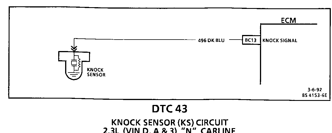
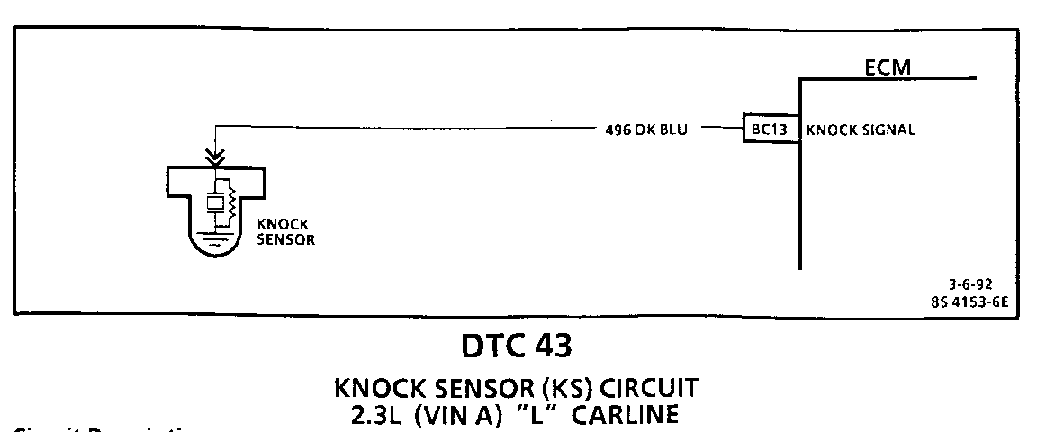
The knock sensor detects engine detonation and the Engine Control Module (ECM) retards the electronic spark timing based on the signal being received. The knock sensor produces an AC signal which is used for knock detection. The amplitude and signal frequency are dependent upon the knock level.
The ECM performs two tests on this circuit to determine if it is operating correctly. If either of the tests fail, a DTC 43 will be set.
o If there is an indication of knock for more than 4.54 seconds over a 5 second interval with the engine running.
o If ECM terminal "BC13" does not indicate increasing Knock Sensor (KS) activity with engine speed.
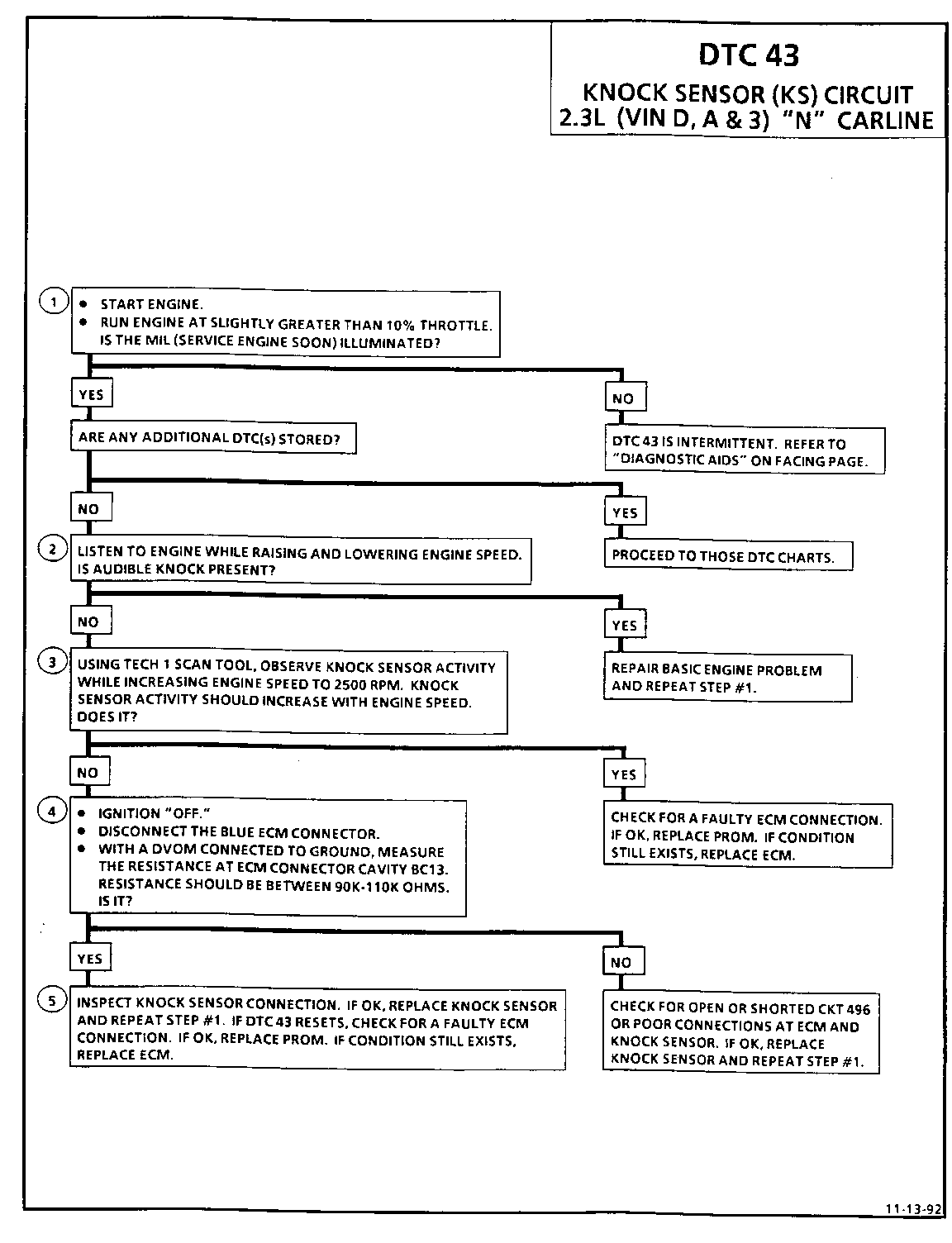
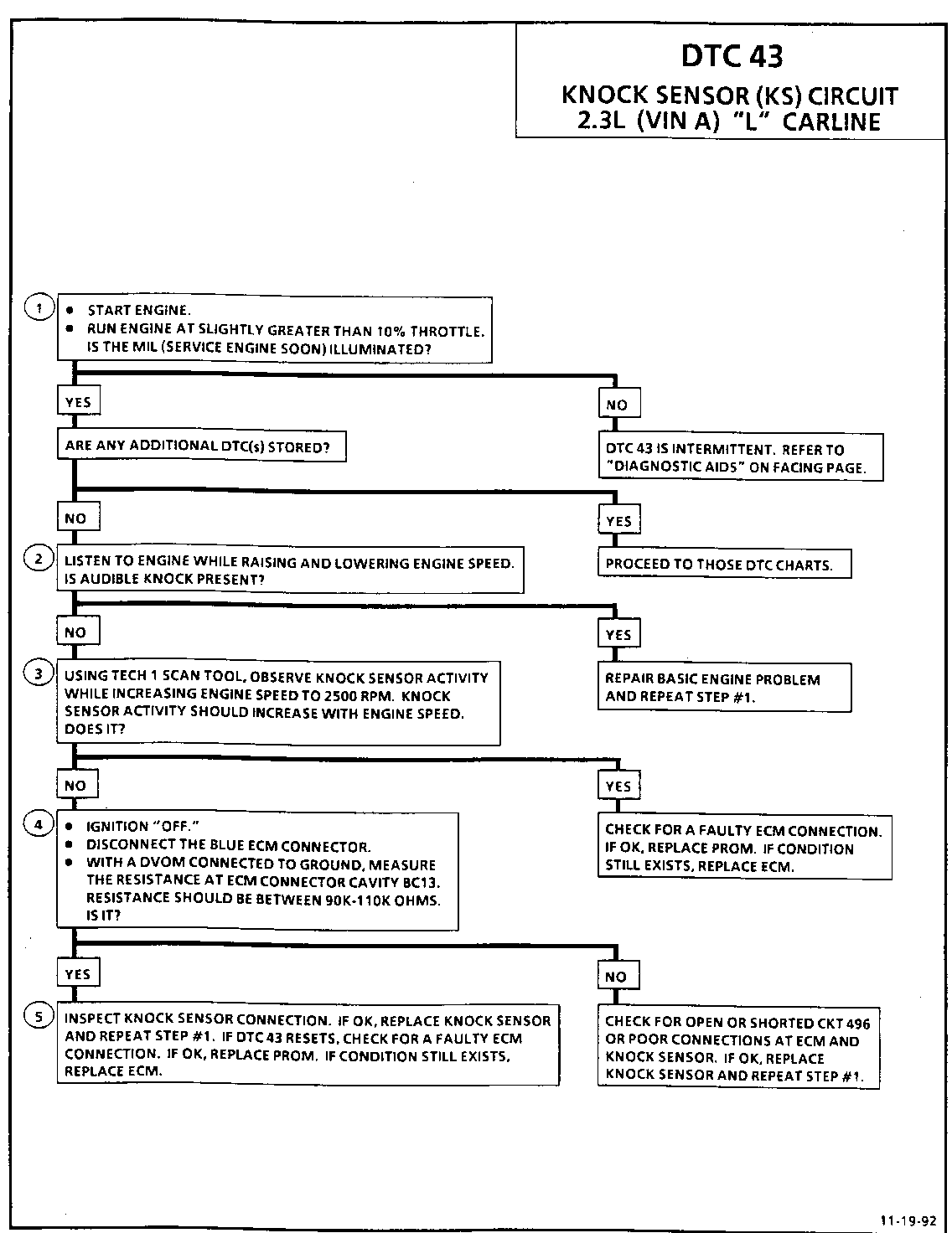
Test Description: Number(s) below refer to circled number(s) on the ----------------- diagnostic chart.
1. If the conditions for the test as described above are met, DTC 43 will be currently set and the MIL (Service Engine Soon) will be illuminated.
2. If the engine has an internal problem which is creating a knock, the knock sensor may be responding to the mechanical noise.
3. The Tech 1 scan tool displays knock sensor activity in counts approximately 35-50 at idle. The counts should rise when engine speed increases or fall when engine speed decreases. This step checks knock sensor activity.
4. This step checks that the internal resistance of knock sensor is within an acceptable range.
5. Check to knock sensor connections for loose terminals or corrosion. A faulty connection will set a DTC 43. If connections are OK, a faulty component will also set a DTC 43.
Diagnostic Aids:
Check CKT 496 for a potential open or short to ground.
Also check for proper installation of the PROM.
Refer to "Intermittents" in "Symptoms," Section "6E3-B".
An "Intermittent" problem may be caused by a poor connection, rubbed through wire insulation, or a wire that is broken inside the insulation.
Any circuitry, that is suspected as causing the intermittent complaint, should be thoroughly checked for backed out terminals, improper mating, broken locks, improperly formed or damaged terminals, poor terminal to wiring connections or physical damage to the wiring harness.
Mechanical engine knock can cause a knock sensor signal. Abnormal engine noise must be corrected before using this chart.
Circuit Description:
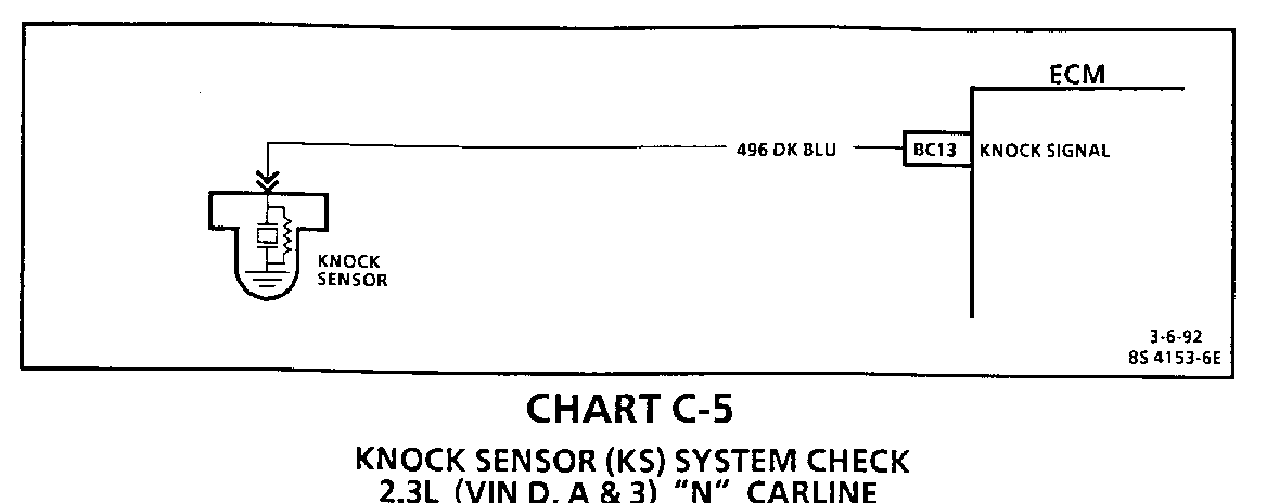
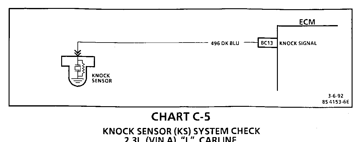
The knock sensor is used to detect engine detonation and the Engine Control Module (ECM) will retard the electronic spark timing based on the signal being received. The knock sensor produces an AC signal. The amplitude and frequency are dependent upon the knock level.
The PROM used with this engine contains the functions which were part of remotely mounted Knock Sensor (KS) modules used on other GM vehicles. The KS portion of the PROM then sends a signal to other parts of the ECM which adjusts the spark timing to retard the spark and reduce the detonation.
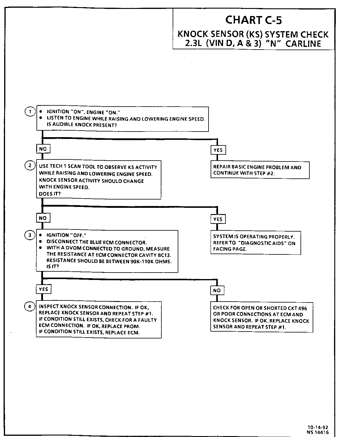
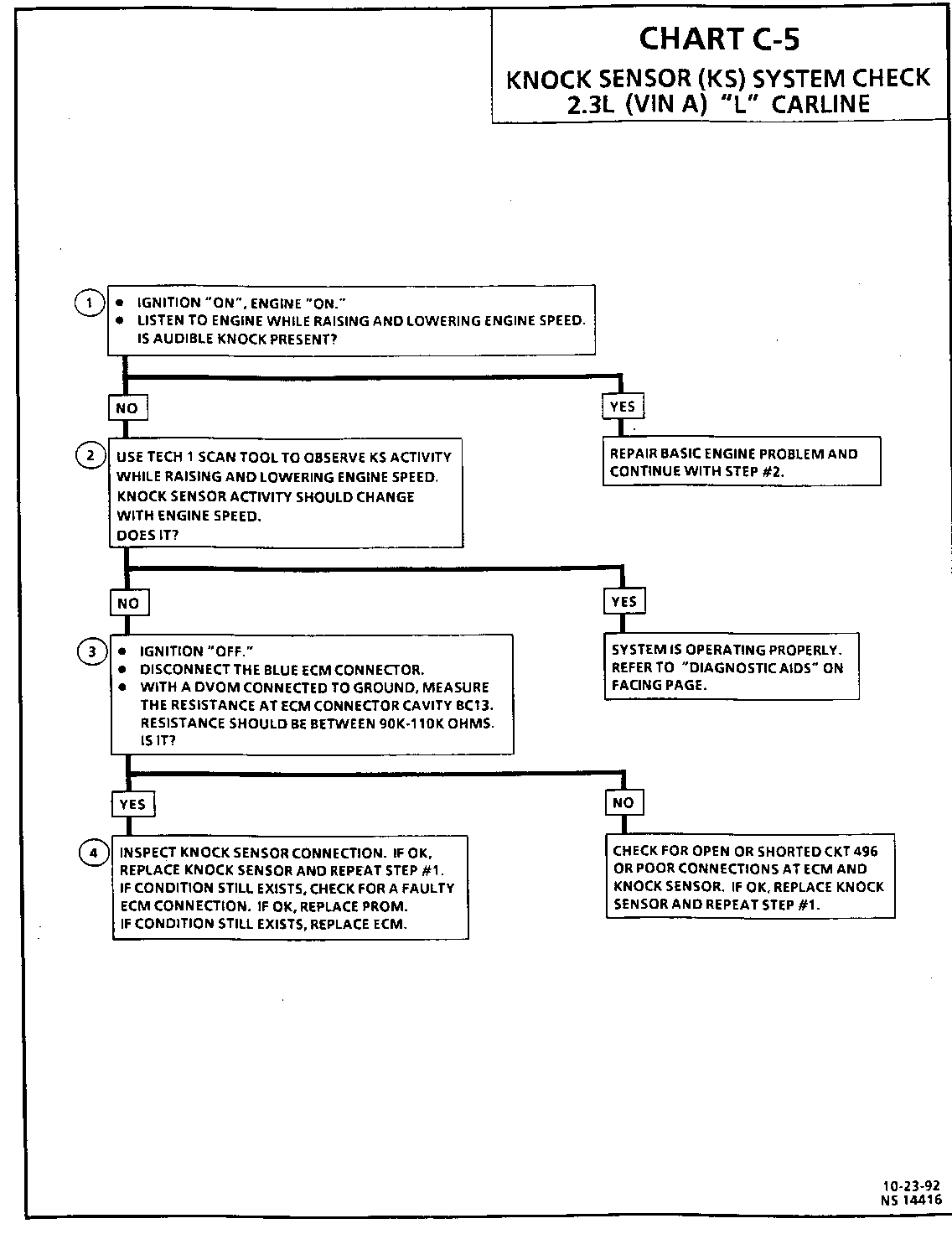
Test Description: Number(s) below refer to circled number(s) on the ----------------- diagnostic chart.
1. If the engine has an internal problem which is creating a knock, the knock sensor may be responding to the mechanical noise.
2. The Tech 1 scan tool displays knock sensor activity in counts approximately 35-50 at idle. The counts should rise when engine speed increases or fall when engine speed decreases. This step checks knock sensor activity.
3. This step checks that the internal resistance of knock sensor is within an acceptable range.
4. Check the knock sensor connections for loose terminals or corrosion. A faulty connection may cause erratic operation. If the connections are OK, check the components for erratic operation.
Diagnostic Aids:
While observing knock signal on the Tech 1 scan tool, there should be an indication that knock is present when detonation can be heard. Detonation is most likely to occur under high engine load conditions.
ON-BOARD DIAGNOSTIC (OBD) SYSTEM CHECK
The On-Board Diagnostic (OBD) system check is an organized approach to identifying a problem created by an electronic engine control system malfunction. It must be the starting point for any driveability complaint diagnosis, because it directs the service technician to the next logical step in diagnosing the complaint.
The Tech 1 data listed in the table may be used for comparison, after completing the OBD system check and finding the on-board diagnostics functioning properly and no diagnostic trouble codes displayed. The "Typical Values" are an average of display values recorded from normally operating vehicles and are intended to represent what a normally functioning system would typically display.
A SCAN TOOL THAT DISPLAYS FAULTY DATA SHOULD NOT BE USED, AND THE PROBLEM SHOULD BE REPORTED TO THE MANUFACTURER. THE USE OF A FAULTY SCAN CAN RESULT IN MISDIAGNOSIS AND UNNECESSARY PARTS REPLACEMENT.
Only the parameters listed below are used in this manual for diagnosing. If a scan reads other parameters, the values are not recommended by General Motors for use in diagnosing. For more description on the values and use of the scan to diagnosis ECM inputs, refer to the applicable diagnosis section in Section "C". If all values are within the range illustrated, refer to "Symptoms," Section "B".
TECH 1 DATA
Idle/Upper Radiator Hose Hot/Closed Throttle/Park or Neutral/"Closed Loop"/ Acc. "OFF"
Scan Position Units Displayed Typical Data Value Refer ------------- --------------- ------------------ to ----- Engine Speed RPM 100 RPM from desired RPM (+/- 50 in drive)
Desired Idle RPM ECM idle command (varies with calibration. temp.)
Eng. Coolant Temp. Celsius/Fahrenheit 85 degrees-115 degrees Celsius
Intake Air Temp. Celsius/Fahrenheit 100-80 degrees Celsius (depends on underhood temp.)
MAP kPa, V 1-3 volts (depends on vacuum & baro pressure)
BARO kPa, V 3-5 volts (depends on altitude & baro pressure)
Throt Position Volts .200-.900 (up to 5.0 at C2 wide open throttle)
Throttle Angle 0-100% 0% (up to 100% at wide C2 open throttle)
O2S mV 1-1000 and varying
Injector Pulse Width m Sec. 1-4 and varying C2
Spark Advance # of Degrees Varies C4
Lo Oct. Knock Ret. # of Degrees Varies
S.T. Fuel Trim Counts Varies
L.T. Fuel Trim Counts 58-198 (see Section "C2")
Loop Status Open/Closed "Closed Loop" (may go open C2 with extended idle)
Fuel Trim Cell Cell Number 18-21 at idle (depends on airflow, RPM, P/N & A/C)
Knock Retard Degrees of Retard 0 C5
Knock Signal Yes/No No C5
KS Activity 0-255 Counts 35-50 (usable for DTC 43) C5
7x Resync Counter 0-255 Counts 0 (usable for DTC 19)
Ign. Control 7x Ref. 0-255 Counts 0-255 (usable for DTC 19)
Ign. Control 7x Syn. "ON/OFF" "ON" (usable for DTC 19 and for misfire diagnosis)
Idle Air Control Counts (steps) 5-60 C2
Park/Neutral Position PN and RDL P-N-- (or-R-DL manual only)
VSS Mph and km/h 0 C8
TCC/Shift Light "ON/OFF" "OFF" ("ON," with TCC ) C8 commanded
System Voltage Volts 13.5 - 14.5 C2
2nd Gear Yes/No (N/A L40 only) No (yes in 2nd or 3rd gear) or yes (man. trans. only)
3rd Gear Yes/No (N/A L40 only) No (yes in 3rd gear) or yes (man. trans. only)
A/C Request Yes/No No (yes, with A/C C10 requested, ie: selector "ON")
A/C Clutch "ON/OFF" "OFF" ("ON," with A/C C10 commanded "ON")
A/C Clutch "ON/OFF" "OFF" ("ON," with A/C C10 commanded "ON")
A/C Ref. Pressure psi/Volts 0-450 psi (varying with high side refrigerant pressure)
Cool Fan Relay "ON/OFF" "OFF" ("ON," with A/C "ON" C12 or hot eng)
Fuel EVAP Purge % 0-100% C3
QDM A Low/Hi Low
QDM 8 Low/Hi Low
QDM C Low/Hi Low
QDM D Low/Hi Low
Calibration ID # Production ECM/Calibration ID (not usable)
Time From Start Min/Sec Varies (engine run time since start)
Circuit Description:
The knock sensor detects engine detonation and the Engine Control Module (ECM) retards the electronic spark timing based on the signal being received. The knock sensor produces an AC signal which is used for knock detection. The amplitude and signal frequency are dependent upon the knock level.
The ECM performs two tests on this circuit to determine if it is operating correctly. If either of the tests fail, a DTC 43 will be set.
o If there is an indication of knock for more than 4.54 seconds over a 5 second interval with the engine running.
o If ECM terminal "BC13" does not indicate increasing Knock Sensor (KS) activity with engine speed.
Test Description: Number(s) below refer to circled number(s) on the ----------------- diagnostic chart.
1. If the conditions for the test as described above are being met, DTC 43 will be currently set and the MIL (Service Engine Soon) will be illuminated.
2. If the engine has an internal problem which is creating a knock, the knock sensor may be responding to the mechanical noise.
3. The Tech 1 scan tool displays knock sensor activity in counts approximately 35-50 at idle. The counts should rise when engine speed increases or fall when engine speed decreases. This step checks knock sensor activity.
4. This step checks that the internal resistance of knock sensor is within an acceptable range.
5. Check the knock sensor connections for loose terminals or corrosion. A faulty connection will set a DTC 43. If connections are OK, a faulty component will also set a DTC 43.
Diagnostic Aids:
Check CKT 496 for a potential open or short to ground.
Also check for proper installation of the PROM.
Refer to "Intermittents" in "Symptoms," Section "6E3-B".
An "Intermittent" problem may be caused by a poor connection, rubbed through wire insulation, or a wire that is broken inside the insulation.
Any circuitry, that is suspected as causing the intermittent complaint, should be thoroughly checked for backed out terminals, improper mating, broken locks, improperly formed or damaged terminals, poor terminal to wiring connections or physical damage to the wiring harness.
Mechanical engine knock can cause a knock sensor signal. Abnormal engine noise must be corrected before using this chart.
Circuit Description:
The knock sensor is used to detect engine detonation and the Engine Control Module (ECM) will retard the electronic spark timing based on the signal being received. The knock sensor produces an AC signal. The amplitude and frequency are dependent upon the knock level.
The PROM used with this engine contains the functions which were part of remotely mounted Knock Sensor (KS) modules used on other GM vehicles. The KS portion of the PROM then sends a signal to other parts of the ECM which adjusts the spark timing to retard the spark and reduce the detonation.
Test Description: Number(s) below refer to circled number(s) on the ----------------- diagnostic chart.
1. If the engine has an internal problem which is creating a knock, the knock sensor may be responding to the mechanical noise.
2. The Tech 1 scan tool displays knock sensor activity in counts approximately 35-50 at idle. The counts should rise when engine speed increases or fall when engine speed decreases. This step checks knock sensor activity.
3. This step checks that the internal resistance of knock sensor is within an acceptable range.
4. Check the knock sensor connections for loose terminals or corrosion. A faulty connection may cause erratic operation. If the connections are OK, check the components for erratic operation.
Diagnostic Aids:
While observing knock signal on the Tech 1 scan tool, there should be an indication that knock is present when detonation can be heard. Detonation is most likely to occur under high engine load conditions.
General Motors bulletins are intended for use by professional technicians, not a "do-it-yourselfer". They are written to inform those technicians of conditions that may occur on some vehicles, or to provide information that could assist in the proper service of a vehicle. Properly trained technicians have the equipment, tools, safety instructions and know-how to do a job properly and safely. If a condition is described, do not assume that the bulletin applies to your vehicle, or that your vehicle will have that condition. See a General Motors dealer servicing your brand of General Motors vehicle for information on whether your vehicle may benefit from the information.
