For 1990-2009 cars only
End Plate and Rotating Group Replacement Belt Drive
Disassembly Procedure
Tools Required
J 7728 Shaft Oil Seal Installer
- Remove the retaining ring (2) by using a punch (1) in the access hole (3).
- Remove the following internal components from the pump housing (3) by gently pushing on the drive shaft (2):
- Remove the O-ring (11) from the pump housing (3)
- Remove the dowel pins (1).
- Remove the drive shaft seal (4).
- Remove the following components from the pressure plate (10):
- Remove the following components from the drive shaft (2):
- Clean all the parts in power steering fluid. Dry the parts thoroughly.
- Inspect the following components for scoring, pitting or chatter marks. Replace the components as needed:
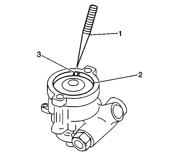
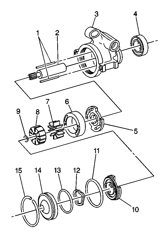
| 2.1. | The pressure plate sub-assembly which consists of the following parts: |
| • | The end cover (14) |
| • | The O-ring seal (13) |
| • | The pressure plate spring (12) |
| • | The pressure plate (10) |
| 2.2. | The drive shaft sub-assembly which consists of the following parts: |
| • | The pump rotor (8) |
| • | The thrust plate (5) |
| • | The drive shaft (2) |
| • | The shaft retaining ring (9) |
| • | The pump ring (6) and the vanes (7) |
| 6.1. | The end cover (14) |
| 6.2. | The pressure plate spring (12) |
| 6.3. | The O-ring (13) |
| 7.1. | The shaft retaining ring (9) |
| 7.2. | The pump rotor (8) |
| 7.3. | The thrust plate (5) |
| • | The pressure plate |
| • | The pump ring |
| • | The rotor |
| • | The vanes |
| • | The thrust plate |
| • | The drive shaft |
Assembly Procedure
- Lubricate the new drive shaft seal (4) with power steering fluid.
- Install the drive shaft seal (4) into the pump housing (3) using J 7728 .
- Install the pump ring dowel pins (1) into the pump housing (3).
- Install the following components onto the drive shaft (2):
- Install the drive shaft sub-assembly into the pump housing (3).
- Install the vanes (7) into the pump rotor (8).
- Install the pump ring (6) in the pump housing (3). Be sure to position the holes in the pump ring (6) correctly onto the dowel pins (1).
- Lubricate a new O-ring (11) with power steering fluid.
- Install the O-ring (11) into the groove in the pump housing (3).
- Install the pressure plate (10).
- Install the pressure plate spring (12).
- Lubricate a new O-ring (13) with power steering fluid.
- Install the O-ring (13) into the end cover (14).
- Lubricate the outer edge of the end cover (14) with power steering fluid.
- Press the end cover (14) into the pump housing (3).
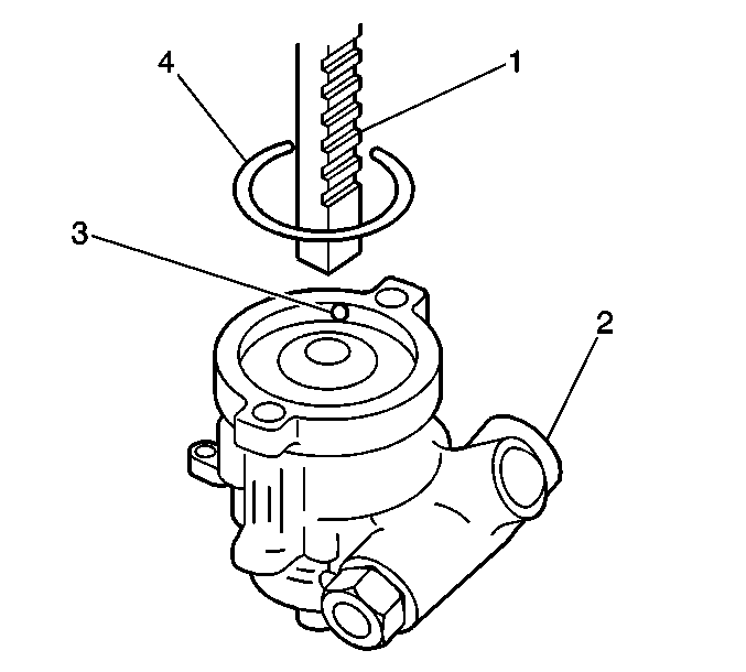
- Install the retaining ring (4) into the groove in the pump housing (2) with the ring opening (1) near the access hole (3).

| 4.1. | The thrust plate (5) |
| 4.2. | The pump rotor (8) |
| 4.3. | A new shaft retaining ring (9) |
End Plate and Rotating Group Replacement Direct Drive
Disassembly Procedure
- Remove the retaining ring (9) by using a punch in the access hole.
- Remove the following internal components from the pump housing (3) by gently pushing on the drive shaft (2):
- Remove the O-ring from the pump housing.
- Remove the dowel pins (1).
- Remove the following components from the pressure plate (10):
- Remove the following components from the drive shaft (2):
- Clean all the parts in power steering fluid. Dry the parts thoroughly.
- Inspect the following components for scoring, pitting or chatter marks. Replace the components as needed:
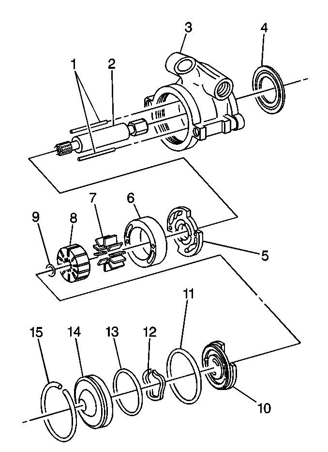
| 2.1. | The pressure plate sub-assembly which consists of the following parts: |
| • | The end cover (14) |
| • | The O-ring seal (13) |
| • | The pressure plate spring (12) |
| • | The pressure plate (10) |
| 2.2. | The drive shaft sub-assembly which consists of the following parts: |
| • | The pump rotor (8) |
| • | The thrust plate (5) |
| • | The drive shaft (2) |
| • | The shaft retaining ring (9) |
| • | The pump ring (6) and the vanes (7) |
| 5.1. | The end cover (14) |
| 5.2. | The pressure plate spring (12) |
| 5.3. | The O-ring (13) |
| 6.1. | The shaft retaining ring (9) |
| 6.2. | The pump rotor (8) |
| 6.3. | The thrust plate (5) |
| • | The pressure plate |
| • | The pump ring |
| • | The rotor |
| • | The vanes |
| • | The thrust plate |
| • | The drive shaft |
Assembly Procedure
- Install the pump ring dowel pins (1) into the pump housing (3).
- Install the following components onto the drive shaft (2):
- Install the drive shaft sub-assembly into the pump housing (3).
- Install the pump ring (6) in the pump housing (3). Be sure to position the holes in the pump ring (6) correctly onto the dowel pins (1).
- Install the vanes (7) into the pump rotor (8).
- Lubricate a new O-ring (11) with power steering fluid.
- Install the O-ring (11) into the groove in the pump housing (3).
- Install the pressure plate (10).
- Install the pressure plate spring (12).
- Lubricate a new O-ring (13) with power steering fluid.
- Install the O-ring (13) into the end cover (14).
- Lubricate the outer edge of the end cover (14) with power steering fluid.
- Press the end cover (14) into the pump housing (3).
- Install the retaining ring (1) into the groove in the pump housing with the ring opening near the access hole (2).

| 2.1. | The thrust plate (5) |
| 2.2. | The pump rotor (8) |
| 2.3. | A new shaft retaining ring (9) |
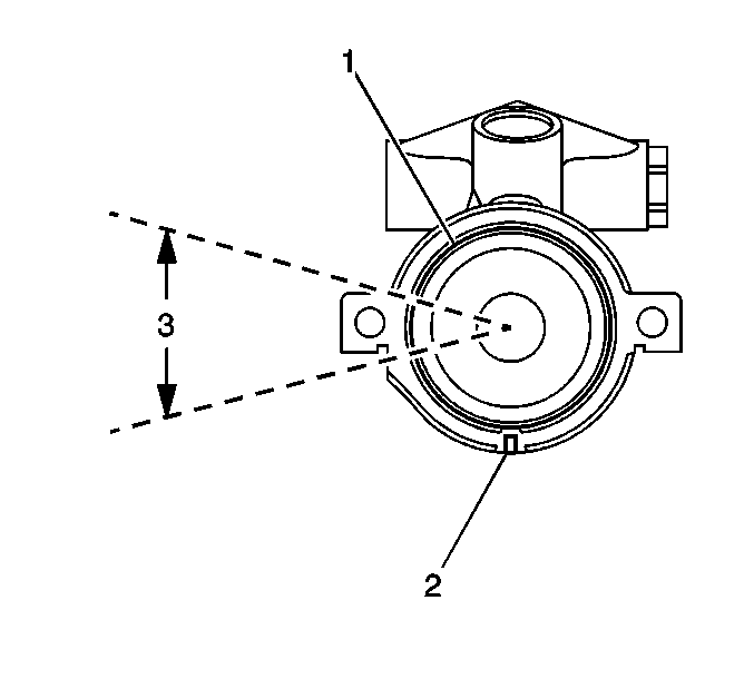
Important: The retaining ring opening (3) must be located next to the mounting boss.
