Removal Procedure
Tools Required
J 22610 Service Boot Clamp Installer
- Remove the rack and pinion steering assembly from the vehicle.
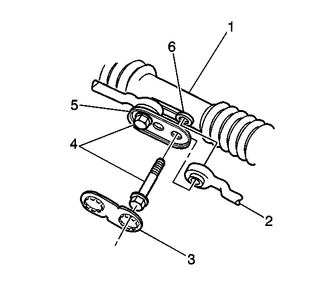
- Remove the lock plate (3) from the inner tie rod bolts (4) and dispose of the lock plate.
- Remove the inner tie rod bolts (4).
- Remove the bolt support plate (5).
- Remove the inner tie rods (2).
- Disconnect the cylinder lines (1) with the attached O-ring seals (2) from the rack and pinion steering assembly (3).
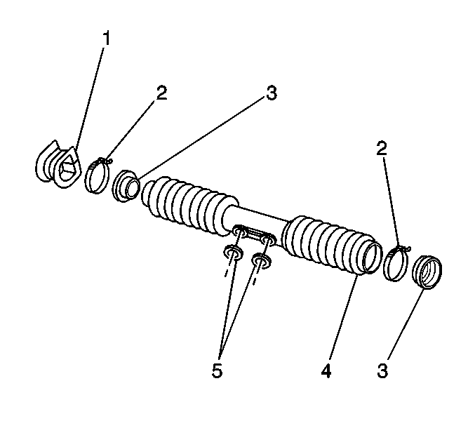
- Cut through the mounting grommets (1) and boot clamps (2) in order to remove them.
- Slide the boot retaining bushings (3) from the rack and pinion boot (4).
- Slide the boot assembly from the rack and pinion housing for removal. The boot assembly consists of the following components captured in the rack and pinion boot (4):


| • | The rack and pinion boot (4) |
| • | The boot retaining bushing (3) |
| • | The center housing cover washers (5) |
Installation Procedure
- Slide the boot retaining bushings (3) from the rack and pinion boot (4).
- Slide the new boot clamps (2) onto rack and pinion boot (4).
- Coat the inner lip of the boot retaining bushings (3) with grease for easier installation.
- Slide the boot retaining bushings (3) back into the rack and pinion boot (4).
- Slide the boot assembly onto the rack and pinion housing.
- Ensure the center housing cover washers (5) are in place in the rack and pinion boot (4).
- Install the inner tie rod bolts (4) through the center housing cover washers (6) and insert into the rack guide.
- Lightly thread the bolts into the rod and rack assembly in order to keep the components properly aligned.
- Install the boot retaining bushing (3) onto the cylinder tube of the rack and pinion housing.
- Slide the new boot clamps (2) over the cylinder end of the rack and pinion housing, then position on the rack and pinion boot (4).
- Slide the rack and pinion boot (4) and the boot retaining bushings (3) until seated in the bushing groove in the housing.
- Position the boot clamps (2) on the rack and pinion boot (4). Use the J 22610 in order to crimp the clamps (2).
- With the O-rings (2) in position, connect the cylinder lines (1) to the rack and pinion housing assembly (3).
- Install the inner tie rod bolts (4) in the following manner:
- Install the new lock plate (3) with the notches in the proper position over the flats of the inner tie rod bolts (4).


Slide these components into the end of the rack and pinion boot (4).

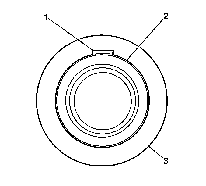
Important: The bridge of the boot clamp (1) must be crimped over the split in the boot retaining bushing (2) in order to ensure proper sealing.

Notice: Use the correct fastener in the correct location. Replacement fasteners must be the correct part number for that application. Fasteners requiring replacement or fasteners requiring the use of thread locking compound or sealant are identified in the service procedure. Do not use paints, lubricants, or corrosion inhibitors on fasteners or fastener joint surfaces unless specified. These coatings affect fastener torque and joint clamping force and may damage the fastener. Use the correct tightening sequence and specifications when installing fasteners in order to avoid damage to parts and systems.
Tighten
| • | Tighten the fittings at the valve end of the housing to 18 N·m (14 lb ft). |
| • | Tighten the fittings at the cylinder end to 28 N·m (20 lb ft). |

| 14.1. | Through the holes in the bolt support plate (5) |
| 14.2. | Through the inner pivot bushing that is part of the inner tie rod (2) |
| 14.3. | Through the center housing cover washer (6) |
| 14.4. | Insert into the rack guide and into the threaded hole in the rod and rack assembly |
Tighten
Tighten the inner tie rod bolts to 90 N·m (65 lb ft).
