For 1990-2009 cars only
Removal Procedure
Tools Required
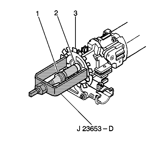
J 23653-D SIR Lock Plate Compressor
- Remove the steering wheel module coil. Allow the SIR coil assembly to hang freely. Refer to the following procedures:
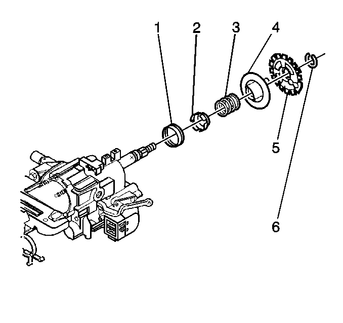
- Remove the shaft lock bearing retainer (1) using the J 23653-D in order to push down the shaft lock (2).
- Remove the shaft lock (5).
- Remove the turn signal cancel cam assembly (4).
- Remove the upper bearing spring (3).
- Remove the upper bearing inner race seat.
- Remove the inner race (1).

Dispose of the bearing retainer (1).

Installation Procedure
Tools Required
J 23653-D SIR Lock Plate Compressor
- Install the inner race (1).
- Install the upper bearing inner race seat.
- Install the upper bearing spring (3).
- Install the turn signal cancel cam assembly (4).
- Install the shaft lock (5). Align the inner block tooth of the lock plate to the block tooth of the race and upper shaft assembly.
- Install the new shaft lock bearing retainer (1). Use the J 23653-D in order to push down the shaft lock.
- Firmly seat the new shaft lock bearing retainer in the groove on the race and upper shaft assembly.
- Install the steering wheel module coil. Refer to the following procedures:

Lubricate the shaft lock with synthetic grease.

