Caution: Do not move the vehicle until a firm brake pedal is obtained. Air in
the brake system can cause loss of brakes with possible personal injury.
Caution: Use only SUPREME 11 or equivalent DOT 3 brake fluid from a clean, sealed
container. Do not use fluid from an open container that may be contaminated
with water. Improper or contaminated fluid will result in damage to components
or loss of braking, with possible personal injury.
Caution: Do not overfill the brake fluid reservoir. Overfilling the brake fluid
reservoir may cause the brake fluid to overflow onto the engine exhaust components
during brake system service. The brake fluid is flammable and
may cause a fire and personal injury if the brake fluid contacts the engine
exhaust system components.
Notice: If any brake component is repaired or replaced such that air is allowed
to enter the brake system, the entire bleeding procedure must be followed.
Notice: Avoid spilling brake fluid on any of the vehicle's painted surfaces,
wiring, cables, or electric connectors. Brake fluid will damage the paint
and the electrical connections. If any fluid is spilled on the vehicle, flush
the area to lessen the damage.
Notice: Prior to bleeding the brakes, the front and rear displacement cylinder
pistons must be returned to the topmost position. The preferred method uses
a Scan Tool to perform the rehoming procedure. If a Scan Tool
is not available, the second procedure may be used, but it is extremely important
that the procedure be followed exactly as outlined.
A bleeding operation is necessary in order to remove air
when air is introduced into the hydraulic brake system.
Bleed the hydraulic system at all four brakes if air has been introduced
through a low fluid level or by disconnecting brake pipes at the master cylinder.
If a brake hose or brake pipe is disconnected at one wheel, bleed
only that one wheel caliper. If brake pipes or hoses are disconnected
at any fitting located between the master cylinder and the brakes,
then only bleed the brake system served by the disconnected pipe or
hose.
With Scan Tool (Preferred Method)
- Using a scan tool, select the Motor Rehome under special functions.
The Motor Rehome function cannot be performed if current DTCs are present.
If DTCs are present, repair the vehicle fault and clear the DTCs before
performing the Motor Rehome function.
- Bleed the entire brake system.
Without Scan Tool
Notice: This method can only be used if the amber ABS warning indicator is not
illuminated and no DTCs are present.
Important: Do not place your foot on the brake pedal through this entire procedure
unless specifically directed to do so.
- Remove foot from the brake pedal.
- Start the engine. Allow the engine to run for at least 10 seconds
while observing the amber ABS warning indicator.
- If the amber ABS warning indicator turns on and stays on after
10 seconds, stop the bleeding procedure. Use a scan tool in order to
diagnose the ABS malfunction.
- If the amber ABS warning indicator turns on for approximately
3 seconds, then turns off and stays off, turn the ignition off.
- Repeat the previous 4 steps again.
- Bleed the entire brake system.
Pressure Bleeding
Tools Required
| • | J 29532 Diaphragm
Type Brake Bleeder |
| • | J 35589 Compact
Brake Bleeder Adapter |
Notice: Pressure bleeding equipment must be of the diaphragm type. It must have
a rubber diaphragm between the air supply and the brake fluid to prevent air,
moisture, and other contaminants from entering the hydraulic system.
- Remove the battery. Refer to
Battery Replacement
in Engine Electrical.
- Remove the bolts from the battery tray.
- Remove the battery tray.
- Clean the brake fluid reservoir cover and the surrounding area.
- Remove the brake fluid reservoir cover.
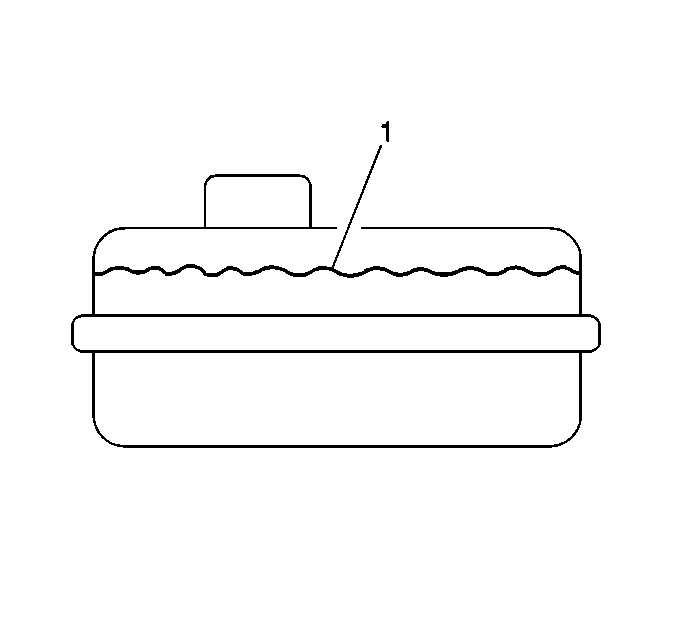
- Inspect the brake fluid
reservoir level. Refer to
Master Cylinder Reservoir Filling
. Add clean brake fluid as required.
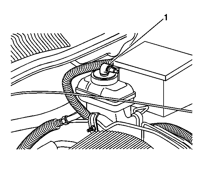
- Connect the J 35589
to the brake fluid reservoir.
- Install the J 35589
to the pressure bleeding equipment.
- Adjust the pressure bleed equipment to 242 kPa (35 psi).
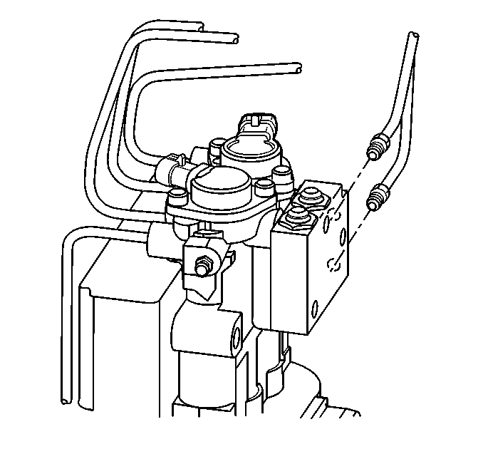
- Bleed the brake pipe connections
on the brake proportioning valve using pressure bleeding equipment that is
connected and pressurized:
| 10.1. | Slowly open the tube nut on the bottom brake pipe on the brake
proportioning valve. Inspect for air in the escaping fluid. |
Notice: Use the correct fastener in the correct location. Replacement fasteners
must be the correct part number for that application. Fasteners requiring
replacement or fasteners requiring the use of thread locking compound or sealant
are identified in the service procedure. Do not use paints, lubricants, or
corrosion inhibitors on fasteners or fastener joint surfaces unless specified.
These coatings affect fastener torque and joint clamping force and may damage
the fastener. Use the correct tightening sequence and specifications when
installing fasteners in order to avoid damage to parts and systems.
| 10.2. | When the air flow
ceases, immediately tighten the tube nut. |
Tighten
Tighten the tube nut to the proportioning valve 23 N·m
(17 lb ft).
| 10.3. | Moving from the bottom to the top, repeat the previous step for
the top brake pipe connection. |
- Complete the following procedures using pressure bleeding equipment
that is connected and pressurized:
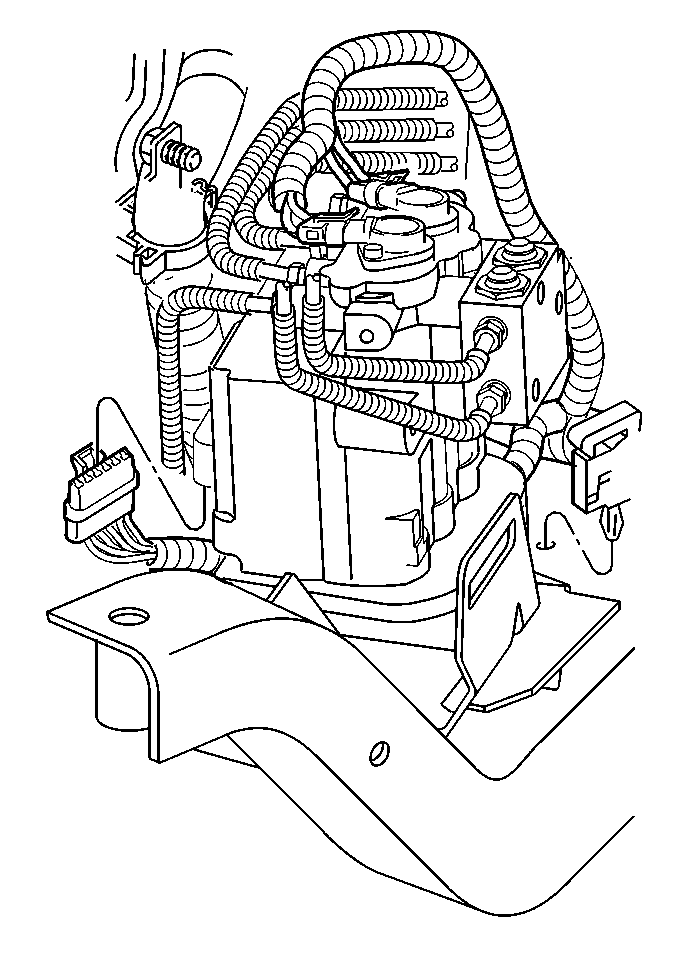
| 11.1. | Attach a clear plastic
bleeder hose to the rearward bleeder valve on the brake modulator. |
| 11.2. | Submerge the opposite hose end in a clean container that is partially
filled with clean brake fluid. |
| 11.3. | Slowly open the bleeder valve. Allow the fluid to flow until no
air is seen in the fluid. |
| 11.4. | Close the valve when the fluid flows without any air bubbles. |
| | Important: Use a shop cloth in order to catch escaping brake fluid. Prevent the
fluid from running down the motor pack case or into the electrical connector.
Do not allow brake fluid to contact any painted surfaces as surface
damage will occur. If brake fluid does contact any surface, flush
the surface with water in order to lessen the damage.
|
| 11.5. | Repeat the previous 4 steps until no air bubbles are present. |
| 11.6. | Relocate the bleeder hose on the forward brake modulator bleeder
valve. |
| 11.7. | Submerge the opposite hose end in a clean container partially
filled with clean brake fluid. |
| 11.8. | Slowly open the bleeder valve. Allow the fluid to flow until no
air is seen in the fluid. |
Notice: Use the correct fastener in the correct location. Replacement fasteners
must be the correct part number for that application. Fasteners requiring
replacement or fasteners requiring the use of thread locking compound or sealant
are identified in the service procedure. Do not use paints, lubricants, or
corrosion inhibitors on fasteners or fastener joint surfaces unless specified.
These coatings affect fastener torque and joint clamping force and may damage
the fastener. Use the correct tightening sequence and specifications when
installing fasteners in order to avoid damage to parts and systems.
| 11.9. | Close the valve
when the fluid flows without any air bubbles. |
Tighten
Tighten the ABS modulator bleeder valves to 9 N·m (80 lb in).
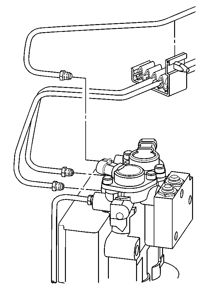
- Bleed the brake modulator
brake pipe connections using pressure bleeding equipment that is connected
and pressurized:
| 12.1. | Slowly open the tube nut on the forward brake pipe on the brake
modulator. Inspect for air in the escaping fluid. |
| 12.2. | When the air flow ceases, immediately tighten the tube nut. |
Tighten
Tighten the tube nut to modulator 23 N·m (17 lb ft).
| 12.3. | Moving from the front to the rear, repeat the previous 2 steps
for the remaining 3 brake pipe connections. |
- Raise and suitably support the vehicle. Refer to
Lifting and Jacking the Vehicle
in General Information.
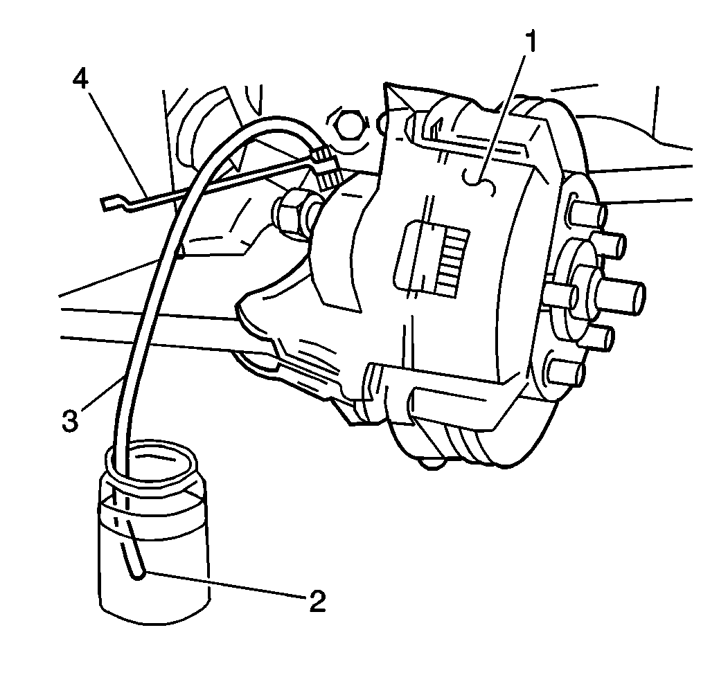
- Use the following bleed
sequence in order to bleed the system:
- Bleed the wheel brakes in the sequence shown above:
Important: Ensure that the bleeder valves do not leak.
- Complete the following steps in order to bleed the brakes:
| 15.1. | Attach a clear plastic bleeder hose (3) to the bleeder
valve at the wheel. |
| 15.2. | Submerge the opposite hose end in a clean container (2)
partially filled with clean brake fluid. |
| 15.3. | Slowly open the bleeder valve and allow the fluid to flow. |
| 15.4. | Close the valve when the fluid begins to flow without any air
bubbles. Tap lightly on the caliper (1) or backing plate in order to
dislodge any trapped air bubbles. |
Tighten
| • | Tighten the front caliper bleeder valves to 13 N·m
(115 lb in). |
| • | Tighten rear caliper bleeder valves to 7 N·m (62 lb in). |
| • | Tighten the rear wheel cylinder bleeder valves to 7 N·m
(62 lb in). |
- Lower the vehicle.
- Remove the pressure bleeding equipment, including the J 35589
.

- Inspect the brake fluid
level in the reservoir (1). Fill the reservoir to the proper level
if necessary.
- Reinstall the brake fluid reservoir cap.
- Install the battery tray.
- Install the battery. Refer to
Battery Replacement
in Engine Electrical.
- Cycle the ignition to the ON then OFF position. Do not start the
engine.
- Apply the brake pedal with moderate force and hold the brake pedal.
Note the pedal travel and feel.
- If the pedal feels firm and constant and pedal travel is not excessive,
start the engine. With the engine running, re-check the pedal travel.
- If the pedal travel is still firm and constant and pedal travel
is not excessive, perform a road test on the vehicle. Make several normal
(non-ABS) stops from a moderate speed in order to ensure proper brake
system function. Allow adequate cooling time between stops.
- If pedal travel feels soft or has excessive travel either initially
or after the engine start, use the following procedure:
| 26.1. | Using the scan tool, release then apply each motor 2-3 times
and cycle each solenoid 5-10 times. |
| 26.2. | When finished, perform the motor rehome procedure to ensure the
pistons are in the upmost position. |
| 26.3. | If a scan tool is not available, remove your foot from the brake
pedal. Start the engine and allow the engine to run for at least 10 seconds
in order to initialize the ABS. Do not drive the vehicle. |
| 26.4. | After 10 seconds, turn the ignition off. |
| 26.5. | Repeat the initialization procedure 5 times in order to
ensure that any trapped air has been dislodged. Repeat the pressure bleeding
procedure starting at Step 1. |
- Perform a road test on the vehicle. Make several normal (non-ABS)
stops from a moderate speed in order to ensure proper brake system function.
Allow adequate cooling time between stops.
Manual Bleeding
Important: In the following procedure, use a suitable container and/or shop cloths
in order to catch and prevent the brake fluid from contacting any painted
surfaces.
- Remove the bolts from the battery tray.
- Remove the battery. Refer to
Battery Replacement
in Engine Electrical.
- Remove the battery tray.
- Remove the bolts from the battery tray.

- Clean the brake fluid
reservoir cover and the surrounding area.
- Remove the brake fluid reservoir cover.
- Inspect the brake fluid level (1). Fill the reservoir to
the correct level if necessary.
- Install the brake fluid reservoir cover.

- Bleed the brake proportioning
valve brake pipe connections:
| 9.1. | Slowly open the tube nut on the bottom brake pipe on the brake
proportioning valve. |
| 9.2. | Depress the brake pedal and hold the pedal until the fluid begins
to flow. |
Tighten
Tighten the tube nut to proportioning valve 23 N·m (17 lb ft).
| 9.4. | Moving from the bottom to the top, repeat the previous step for
the top brake pipe connection. |

- Attach the bleeder hose
to the rearward bleeder valve.
- Submerge the opposite hose end in a clean container partially
filled with clean brake fluid.
- Slowly open the rearward bleeder valve.
- Depress the brake pedal and hold the pedal until the fluid begins
to flow.
- Close the valve and release the brake pedal.
Important: Once the fluid is visibly flowing from both modulator bleeder valves,
the ABS brake modulator assembly is sufficiently full of fluid. The assembly
may not be completely purged of air. At this point, move to the wheel
brakes and bleed the brakes. This ensures that the lowest points in
the system are completely free of air.
- Repeat the previous 3 steps until air bubbles are no longer present.
- Relocate the bleeder hose to the forward brake modulator bleeder
valve.
- Submerge the opposite hose end in a clean container partially
filled with clean brake fluid.
- Slowly open the forward bleeder valve.
- Depress the brake pedal and hold the pedal until the fluid begins
to flow.
- Close the valve and release the brake pedal.
- Repeat the previous 3 steps until air bubbles are no longer
present.
Tighten
Tighten the ABS brake modulator bleeder valves to 9 N·m
(80 lb in).

- Use the following bleed
sequence to bleed the system
- Bleed the wheel brakes in the sequence shown above:
Important: Ensure that the bleeder valves do not leak.
- Complete the following steps in order to bleed the brakes:
| 23.1. | Attach a clear plastic bleeder hose (3) to the bleeder
valve at the wheel. |
| 23.2. | Submerge the opposite hose end in a clean container (2)
partially filled with clean brake fluid. |
| 23.3. | Slowly open the bleeder valve and allow the fluid to flow. |
| 23.4. | Close the valve when the fluid begins to flow without any air
bubbles. Tap lightly on the caliper (1) or backing plate in order to
dislodge any trapped air bubbles. |
Tighten
| • | Tighten the front caliper bleeder valves to 13 N·m
(115 lb in). |
| • | Tighten rear caliper bleeder valves to 7 N·m (62 lb in). |
| • | Tighten the rear wheel cylinder bleeder valves to 7 N·m
(62 lb in). |
- Lower the vehicle.

- Remove the brake fluid
reservoir cover.
- Inspect the brake fluid level in the reservoir (1). Fill
the reservoir to the correct level if necessary.
- Install the brake fluid reservoir cover.
- Install the battery tray bolts.
Tighten
Tighten the bolts to 6 N·m (53 lb in).
- Install the battery tray.
- Install the battery. Refer to
Battery Replacement
in Engine Electrical.
- Cycle the ignition to the ON then OFF position. Do not start the
engine. Apply the brake pedal with moderate force and hold the pedal. Note
the pedal travel and feel.
- If the pedal feels firm and constant and pedal travel is not excessive,
start the engine. With the engine running, recheck the pedal travel.
- If the pedal feel is still firm and constant and pedal travel
is not excessive, perform a vehicle road test. Make several normal (non-ABS)
stops from a moderate speed in order to ensure proper brake system
function.
- If pedal feel is soft or has excessive travel either initially
or after engine start, use the following procedure:
| 34.1. | Using the scan tool, release then apply each motor 2-3 times
and cycle each solenoid 5-10 times. |
| 34.2. | When finished, perform the motor rehome procedure in order to
ensure the pistons are in the upmost position. Do not drive the vehicle. |
| 34.3. | If a scan tool is not available, remove your foot from the brake
pedal, then start the engine. Allow the engine to run for at least 10 seconds
in order to initialize the ABS. Do not drive the vehicle. |
| 34.4. | After 10 seconds, turn off the ignition. |
- Repeat the initialization procedure 5 times in order to
dislodge any air in the system.
- Repeat the manual bleeding procedure, starting at Step 1.
- Perform a vehicle road test. Make several normal (non-ABS) stops
from a moderate speed in order to ensure proper brake system function.


