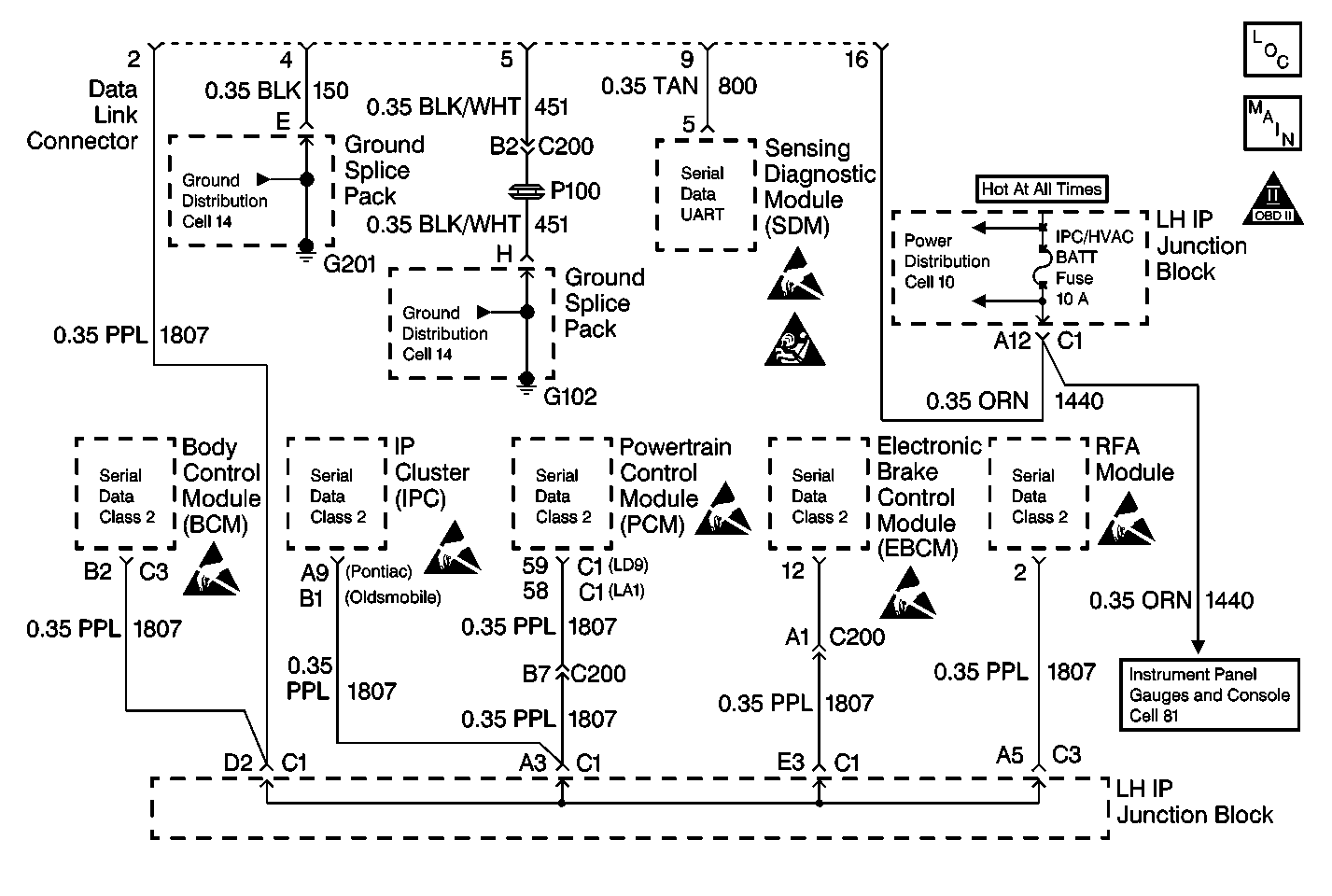
Circuit Description
The serial data link is a communication line between the PCM, Instrument Cluster and the EBCM.
Conditions for Setting the DTC
DTC C1267 sets along with DTC U1300.
DTC C1267 can be set any time the ignition is ON.
A malfunction exists if CKT 1807 is shorted to ground resulting in no communication to the PCM or any other controller.
Action Taken When the DTC Sets
| • | A malfunction DTC stores. |
| • | ABS and ETS remain functional. |
| • | No action towards the electronic brake control relay is taken. |
| • | No action towards the ABS warning indicator is taken. |
Conditions for Clearing the DTC
| • | The condition for DTC C1267 is no longer present. |
| • | The use of the scan tool CLEAR DTCs function. |
| • | DTC C1267 clears after 100 drive cycles with no DTCs detected. A drive cycle consists of starting the vehicle, driving the vehicle over 16 km/h (10 mph), stopping and then turning the ignition OFF. |
Diagnostic Aids
| • | Perform the Powertrain OBD System Check before beginning this DTC table. This eliminates the PCM as a possible source of the malfunction. |
| • | The following conditions may cause an intermittent malfunction: |
| - | Rubbed-through wire insulation. |
| - | Refer to Diagnostic Starting Point in Data Link Communications for serial data line diagnosis. |
| • | Use the enhanced diagnostic function of the scan tool in order to check the frequency of the malfunction. Refer to Scan Tool Diagnostics . |
The malfunction may be intermittent. Try performing the tests shown while "wiggling" wiring and connectors, this can often cause the malfunction to appear. PCM DTCs will likely be set along with DTC C1267.
DTC U1300 will only be able to be read as a history code since the scan tool uses the same serial data circuit. If CKT 1807 is shorted to ground, no communication with the scan tool will be possible.
Step | Action | Value(s) | Yes | No |
|---|---|---|---|---|
1 | Was the ABS Diagnostic System Check performed? | -- | Go to Step 2 | |
2 |
Is the measured resistance within the specified value? | OL (Infinite) | Go to Diagnostic Starting Point in Data Link Communications | Go to Step 3 |
3 | Repair short to ground in CKT 1807. Is the repair complete? | -- | -- |
