For 1990-2009 cars only
Removal Procedure
Tools Required
| • | J 38400 Brake Shoe Spanner and Spring Remover |
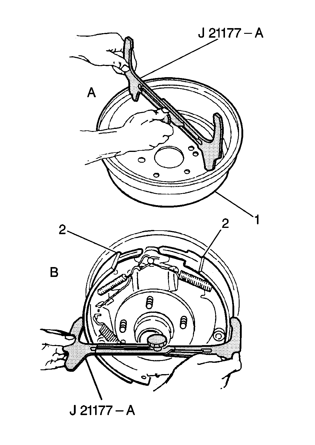
| • | J 21177-A Drum-to-Brake Shoe Clearance |
- Raise the vehicle. Refer to Lifting and Jacking the Vehicle in General Information.
- Remove the brake drums. Refer to Brake Drum Replacement .
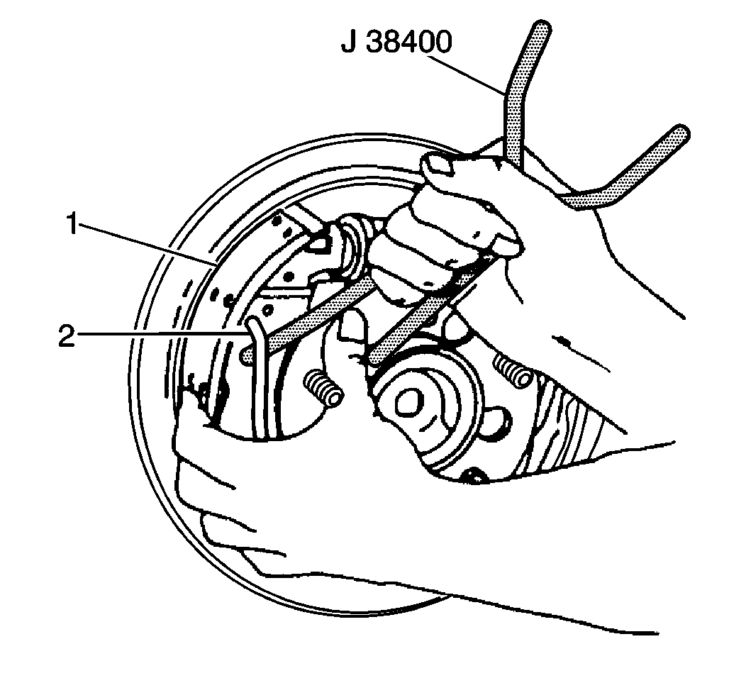
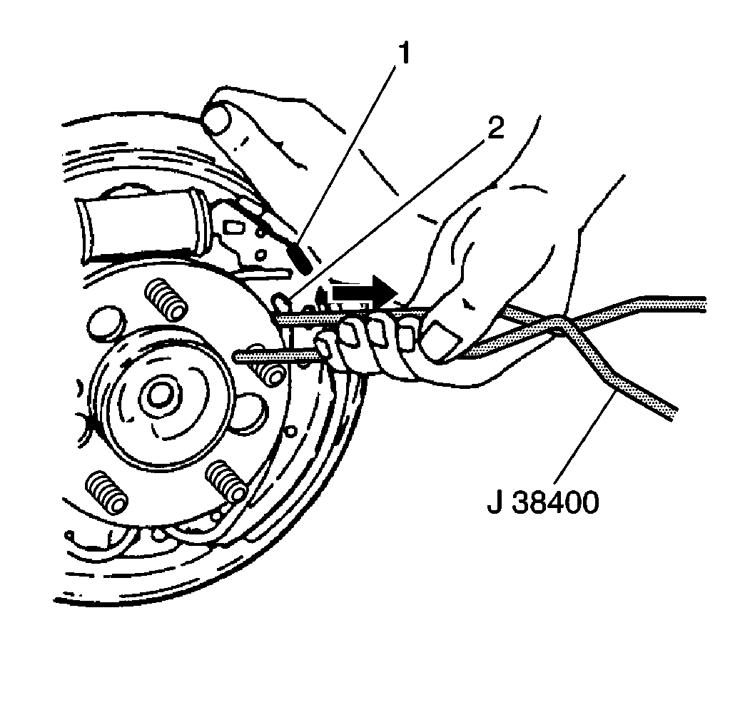
- Remove the adjuster spring (1).
- Use the J 38400 to spread the brake shoes.
- Remove the adjuster assembly.
- Remove the adjuster actuator from the brake shoe.
- Using the hook end of the J 38400 lift or pull the return spring from the brake shoe.
- Remove the brake shoe from the backing plate.
- Using the hook end of the J 38400 lift or pull the return spring from the brake shoe.
- Remove the brake shoe from the backing plate.
- Twist the brake shoe and remove the park brake cable from the lever.
- Mount the brake shoe in a vise.
- Remove the clip and the park brake lever from the brake shoe.
- Remove the return spring from the backing plate. The park brake cable clip will require removal.
- Disassemble the adjuster assembly and clean in denatured alcohol.
- Clean all parts in denatured alcohol.
- Inspect all of the brake system components.
- Replace any brake system components that are worn or damaged.
- Inspect the wheel cylinder for the following conditions. Repair or replace as necessary.
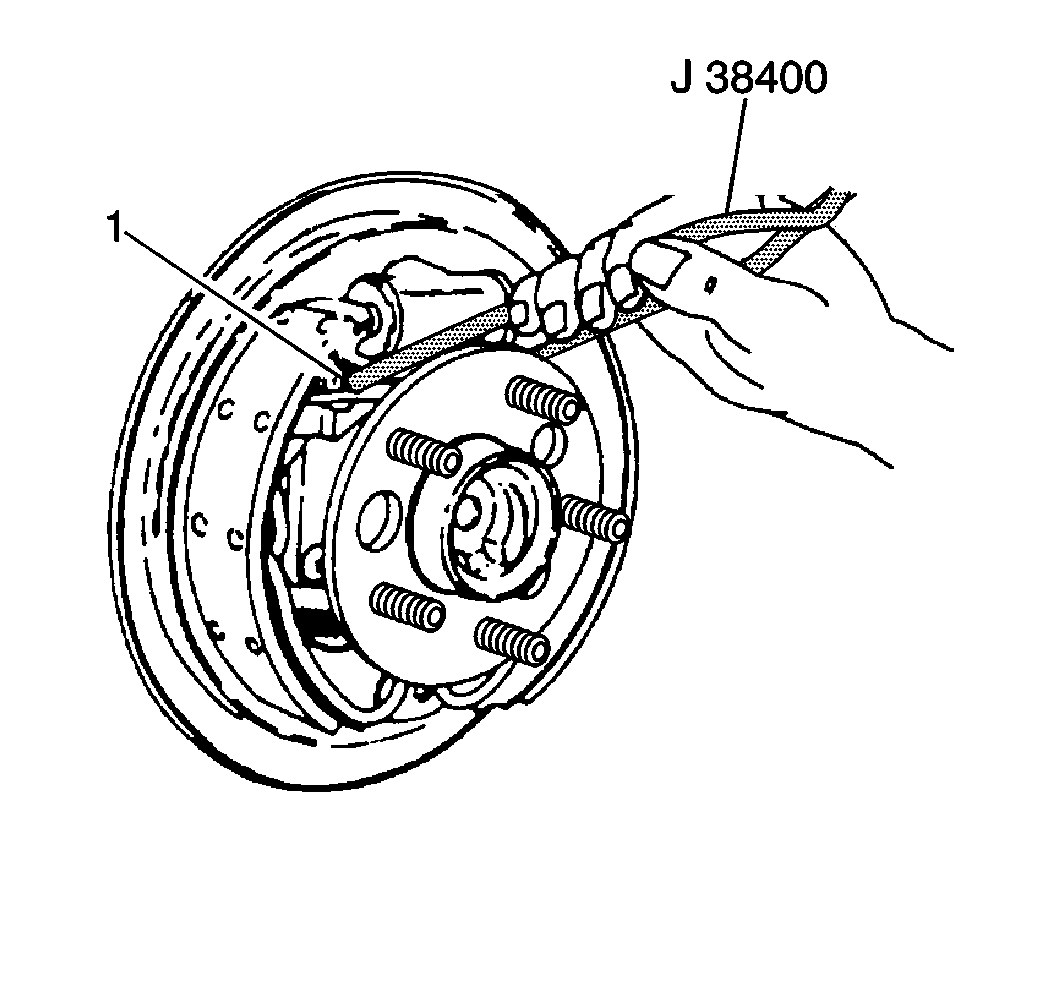
Notice: Do not over stretch the adjuster spring. Damage can occur if the spring is over stretched.
| • | Use the J 38400 in order to pry the loop end of the adjuster spring from the adjuster actuator. |
| • | Disengage the other end of the adjuster spring from the brake shoe. |
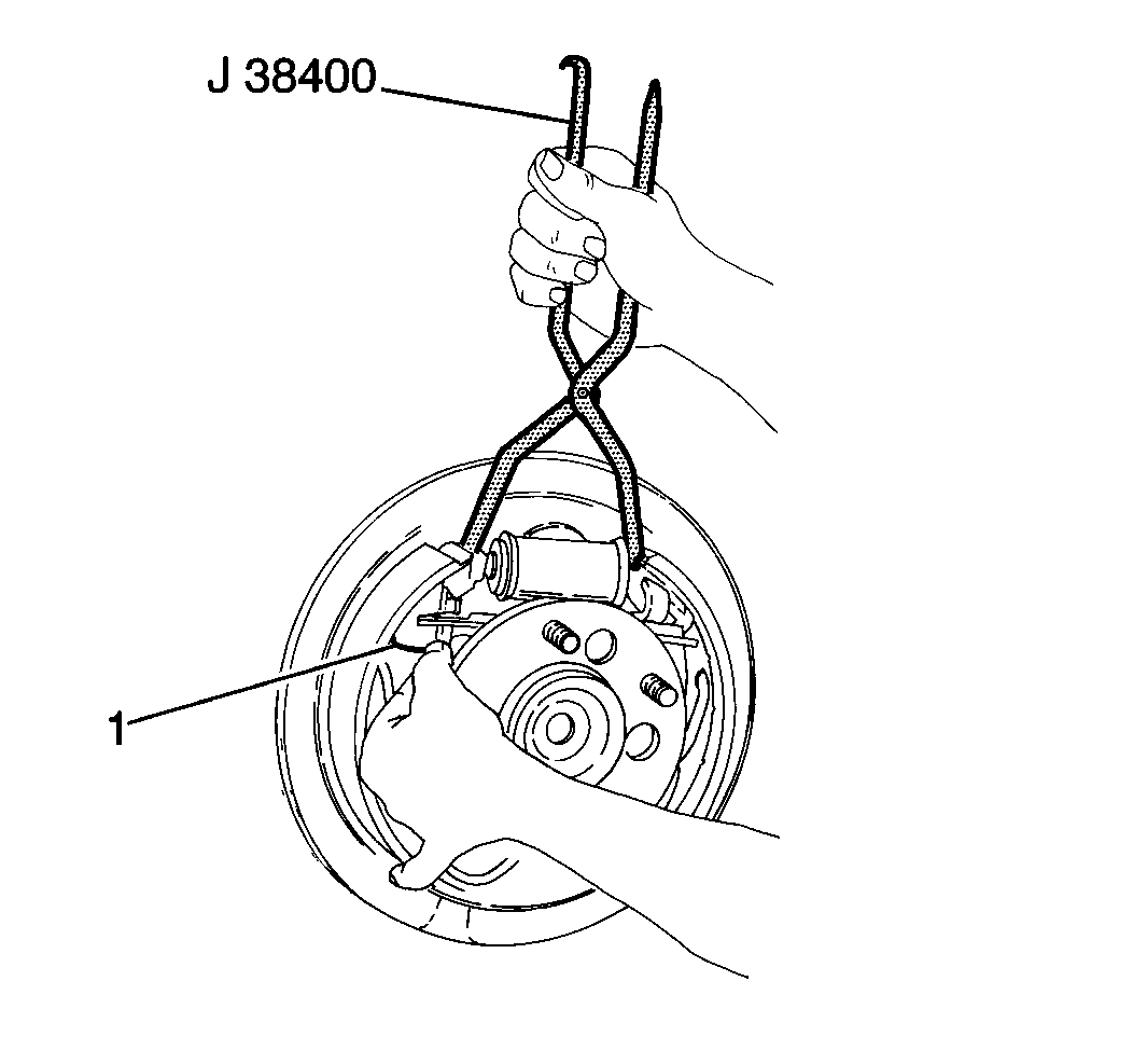
Caution: Keep fingers away from rear brake shoe springs to prevent fingers from being pinched between spring and shoe web or spring and backing plate.
| • | Brake fluid leakage |
| • | Worn or damaged dust boots |
Installation Procedure
- Apply GM P/N 18010908 silicone grease (or equivalent) to the following areas.
- Install the parking brake lever to the brake shoe.
- Install a new parking brake lever clip.
- Install the return spring to the backing plate.
- Install the parking brake cable clip.
- Connect the parking brake cable to the parking brake lever.
- Position the brake shoe in place.
- Using the hook end of the J 38400 lift or pull the return spring and install in the slotted hole on the brake shoe.
- Position the other brake shoe to the backing plate.
- Using the hook end of the J 38400 lift or pull the return spring and install in the slotted hole on the brake shoe.
- Install the adjuster actuator to the brake shoe.
- Use the J 38400 in order to spread the brake shoes.
- Install the adjuster assembly (2).
- Install the adjuster spring in the brake shoe.
- Use the J 38400 and hook the loop end of the adjuster spring on the adjuster actuator.
- Note the following items in order to ensure the proper positioning and function of the adjuster actuator:
- Hold the bottom of the brake shoe with the adjuster actuator. Use the J 38400 and move the brake shoe to the apply direction. Watch for proper rotation of the star wheel.
- Using the J 21177-A measure the brake drum and the brake shoes.
- Adjust the brakes.
- Install the brake drums. Refer to Brake Drum Replacement .
- Lower the vehicle.
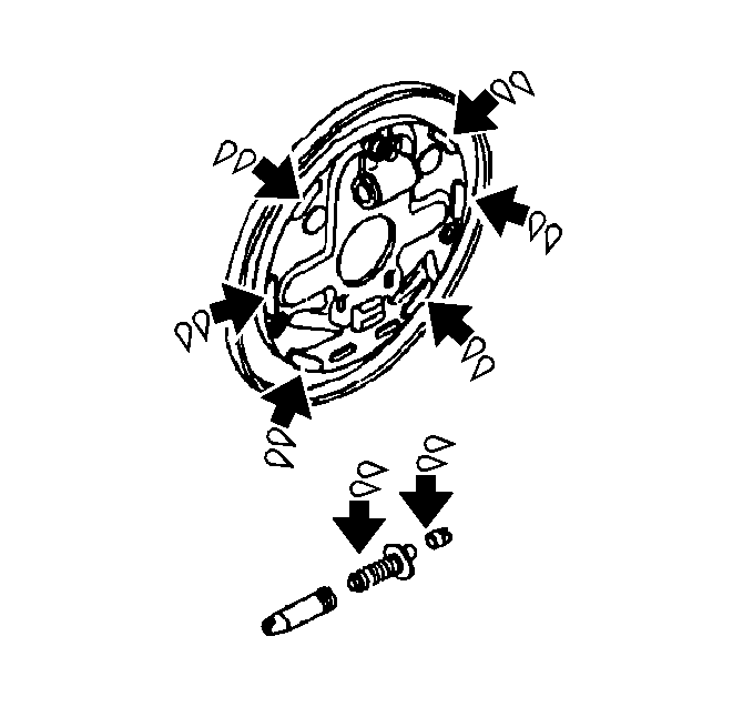
| • | The six brake shoe contact points on the backing plate. |
| • | The adjuster threads |
| • | The inside diameter of the adjuster socket |
| • | The hole and area on the brake shoe for the adjuster actuator |
| • | The pin and the contact area on the park brake lever |
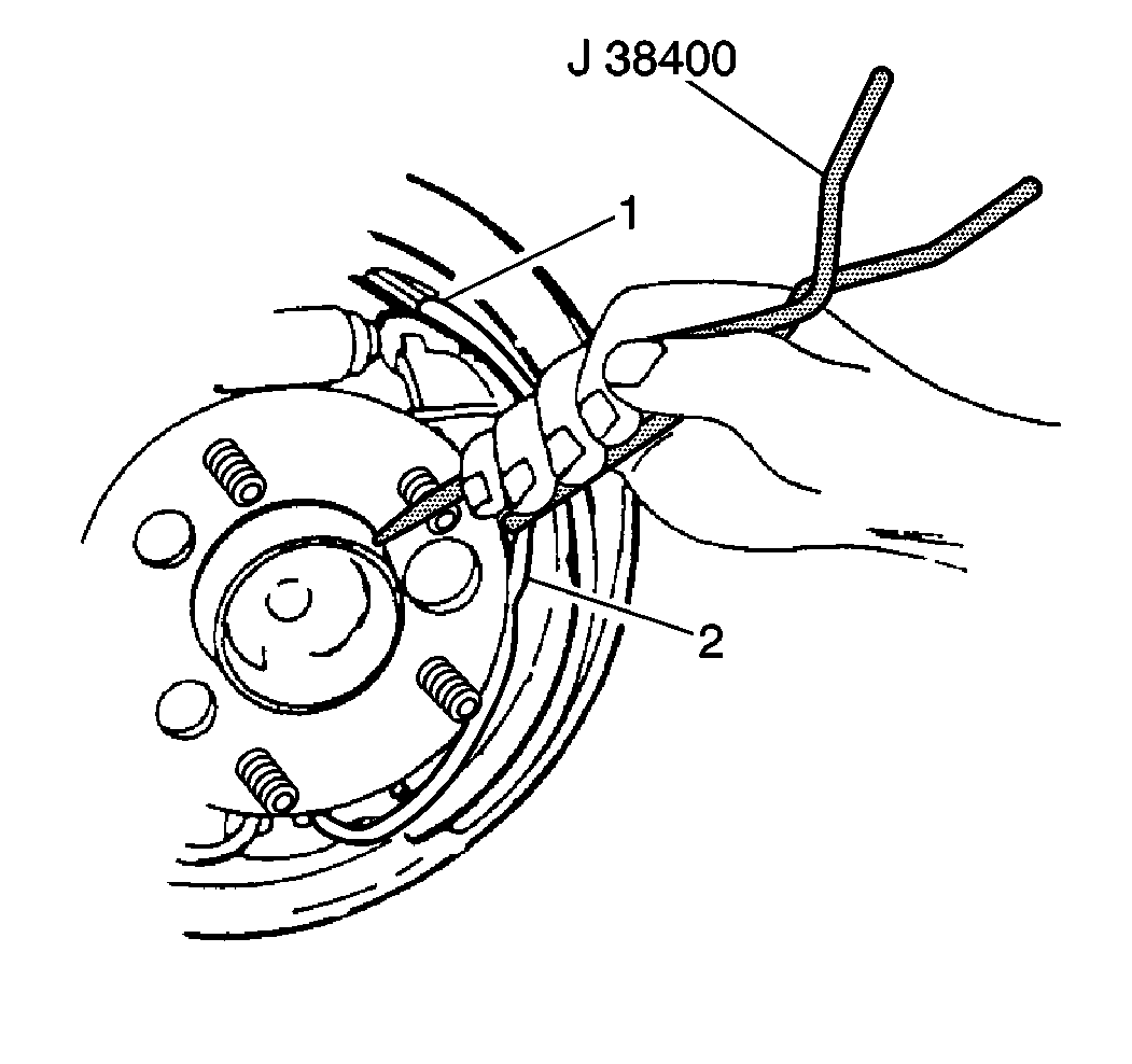
Caution: Keep fingers away from rear brake shoe springs to prevent fingers from being pinched between spring and shoe web or spring and backing plate.


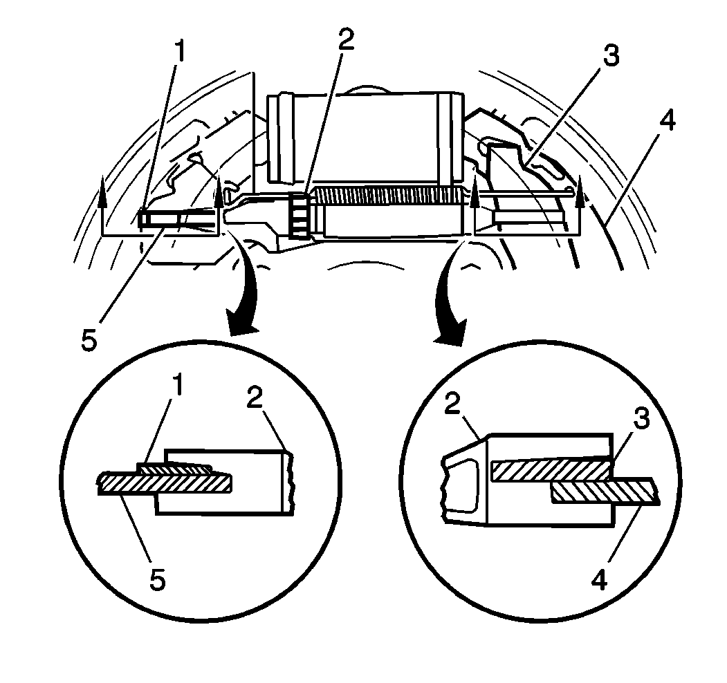
Important: Ensure the adjuster (2) and brake shoe (4) and park brake actuator (3) properly.

Notice: Do not over stretch the adjuster spring. Damage can occur if the spring is over stretched.
| • | The adjuster actuator pivots in the shoe web slot. |
| • | The notch in the adjuster actuator rests on the step in the adjusting screw notch. |
| • | The arm of the adjuster actuator rests freely on the star wheel teeth of the adjuster screw, not trapped under the teeth at a downward angle. |
