Rear Brake Hose Replacement Disc
Removal Procedure
Caution: Refer to Brake Fluid Irritant Caution in the Preface section.
Notice: Refer to Brake Fluid Effects on Paint and Electrical Components Notice in the Preface section.
- Raise and suitably support the vehicle. Refer to Lifting and Jacking the Vehicle in General Information.
- Remove the rear wheel and tire assembly. Refer to Tire and Wheel Removal and Installation in Tires and Wheels.
- Clean the dirt and foreign material from the brake hoses and fittings.
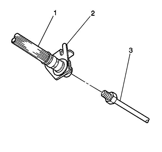
- Remove the rear brake pipe (3) from the brake hose (1), then cap or plug the brake pipe end.
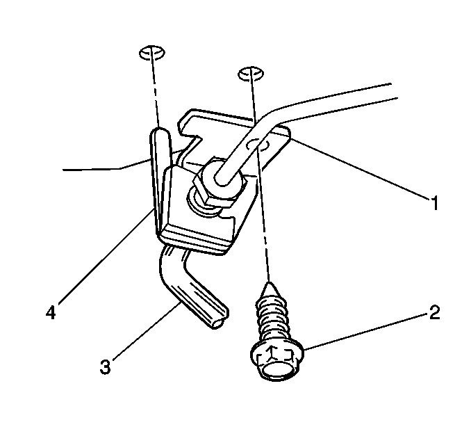
- Remove the retainer clip (4) from the brake hose (3).
- Remove the brake hose (3) from the bracket (1).
- Remove the rear brake hose bracket retaining bolt (2) from the rear brake hose bracket (1).
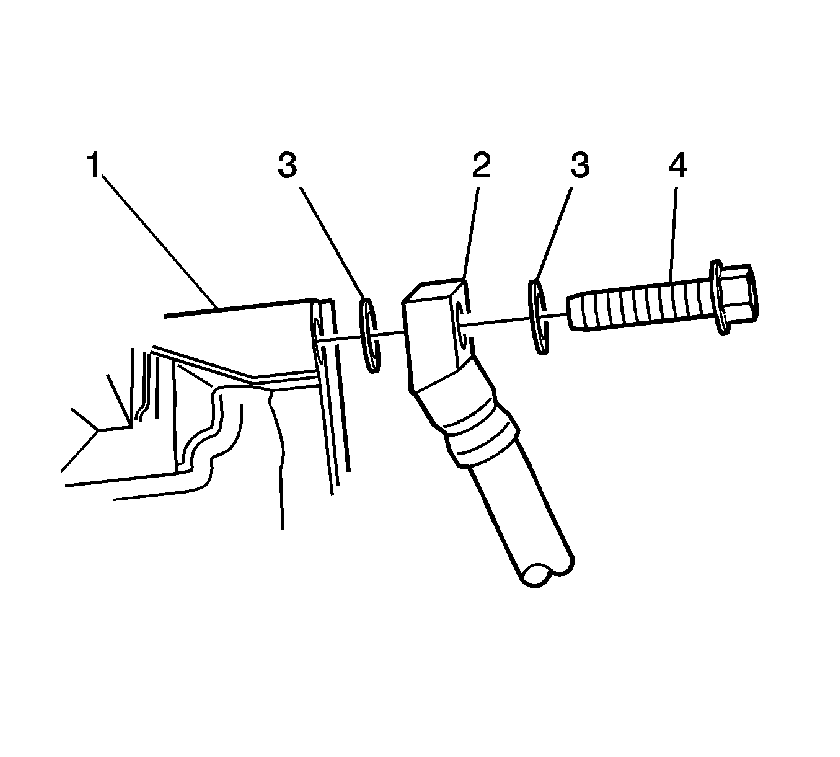
- Remove the rear brake hose banjo bolt (4) from the rear brake hose (2) and caliper (1).
- Discard the 2 copper brake hose gaskets (3) and remove the brake hose (2) from the vehicle.

Important: Install a rubber cap or plug to the exposed brake pipe fitting end to prevent brake fluid loss and contamination.


Installation Procedure
- Assemble the 2 copper brake hose gasket (3) and the rear brake hose banjo bolt (4) to the brake hose (2).
- Install the rear brake hose banjo bolt (4) the copper gaskets (3) and the brake hose (2) to the caliper (1).
- Install the rear brake hose bracket retaining bolt (2) to the rear brake hose bracket (1).
- Install the brake hose (3) to the bracket (1).
- Install the retainer clip (4) to the brake hose (3).
- Remove the rubber cap or plug from the exposed brake pipe end and install the rear brake pipe (3) to the brake hose (1).
- Bleed the brake hydraulic system. Refer to Hydraulic Brake System Bleeding .
- Install the rear wheel and tire assembly. Refer to Tire and Wheel Removal and Installation in Tires and Wheels.
- Visually inspect that the hose does not make contact with any part of the suspension. If the hose makes contact, remove the hose and correct the condition.
- Lower the vehicle.

Notice: Use the correct fastener in the correct location. Replacement fasteners must be the correct part number for that application. Fasteners requiring replacement or fasteners requiring the use of thread locking compound or sealant are identified in the service procedure. Do not use paints, lubricants, or corrosion inhibitors on fasteners or fastener joint surfaces unless specified. These coatings affect fastener torque and joint clamping force and may damage the fastener. Use the correct tightening sequence and specifications when installing fasteners in order to avoid damage to parts and systems.
Tighten
Tighten the rear brake hose banjo bolt to 50 N·m (37 lb ft).

Tighten
Tighten the retaining bolt to 25 N·m (18 lb ft).

Tighten
Tighten thebrake pipe fitting to 23 N·m (17 lb ft).
Rear Brake Hose Replacement Drum
Removal Procedure
Caution: Refer to Brake Fluid Irritant Caution in the Preface section.
Notice: Refer to Brake Fluid Effects on Paint and Electrical Components Notice in the Preface section.
- Raise and suitably support the vehicle. Refer to Lifting and Jacking the Vehicle in General Information.
- Remove the rear wheel and tire assembly. Refer to Tire and Wheel Removal and Installation in Tires and Wheels.
- Clean the dirt and foreign material from the brake hoses and fittings.
- Remove the rear brake pipe (3) from the brake hose (1), then cap or plug the brake pipe end.
- Remove the retainer clip (4) from the brake hose (3).
- Remove the brake hose (3) from the bracket (1).
- Remove the rear brake hose bracket retaining bolt (2) from the rear brake hose bracket (1).
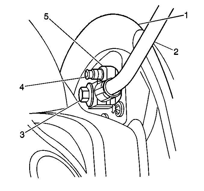
- Remove the rear brake hose banjo bolt (3) from the rear brake hose (2) and wheel cylinder (5).
- Discard the 2 copper brake hose gaskets and remove the brake hose (2) from the vehicle.

Important: Install a rubber cap or plug to the exposed brake pipe fitting end to prevent brake fluid loss and contamination.


Installation Procedure
- Assemble the 2 copper brake hose gaskets and the rear brake hose banjo bolt (3) to the brake hose (2).
- Install the rear brake hose banjo bolt (3) the copper gaskets and the brake hose (2) to the wheel cylinder (5).
- Install the rear brake hose bracket retaining bolt (2) to the rear brake hose bracket (1).
- Install the brake hose (3) to the bracket (1).
- Install the retainer clip (4) to the brake hose (3).
- Remove the rubber cap or plug from the exposed brake pipe end and install the rear brake pipe (3) to the brake hose (1).
- Bleed the brake hydraulic system. Refer to Hydraulic Brake System Bleeding .
- Install the rear wheel and tire assembly. Refer to Tire and Wheel Removal and Installation in Tires and Wheels.
- Visually inspect that the hose does not make contact with any part of the suspension. If the hose makes contact, remove the hose and correct the condition.
- Lower the vehicle.

Notice: Use the correct fastener in the correct location. Replacement fasteners must be the correct part number for that application. Fasteners requiring replacement or fasteners requiring the use of thread locking compound or sealant are identified in the service procedure. Do not use paints, lubricants, or corrosion inhibitors on fasteners or fastener joint surfaces unless specified. These coatings affect fastener torque and joint clamping force and may damage the fastener. Use the correct tightening sequence and specifications when installing fasteners in order to avoid damage to parts and systems.
Tighten
Tighten the rear brake hose banjo bolt to 50 N·m (37 lb ft).

Tighten
Tighten the retaining bolt to 25 N·m (18 lb ft).

Tighten
Tighten the fitting to 23 N·m (17 lb ft).
