Tools Required
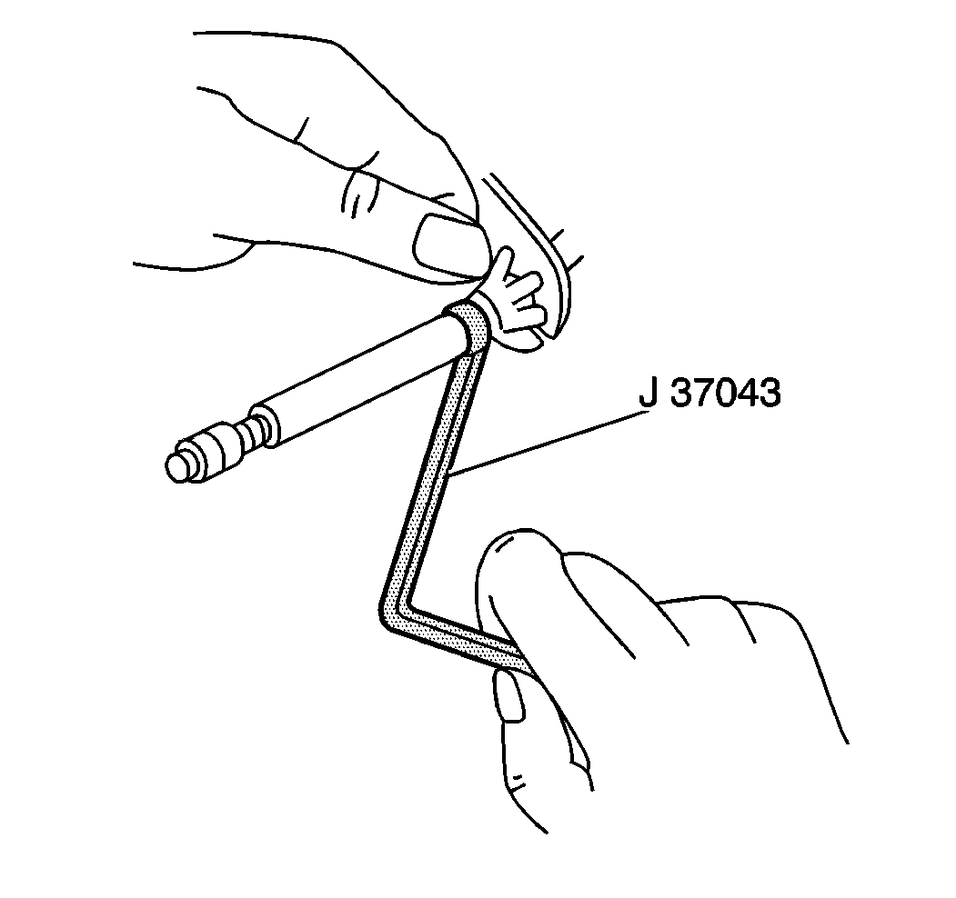
J 37043 Parking Brake Cable Release Tool
Removal Procedure
- Remove the center console. Refer to Front Floor Console Replacement in Instrument Panel, Gages and Console.
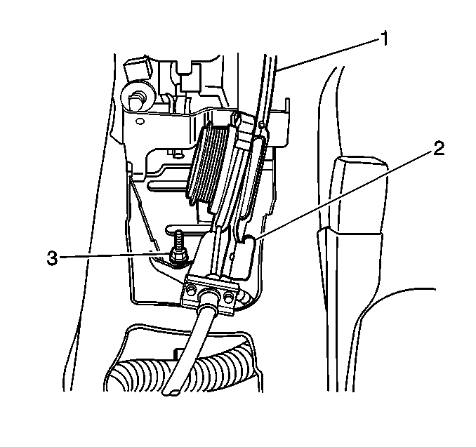
- Remove the parking brake indicator switch (2).
- Raise and suitably support the vehicle. Refer to Lifting and Jacking the Vehicle in General Information.
- Insure that the park brake lever is in the released position.
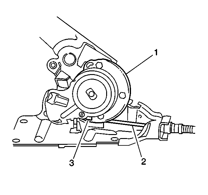
- Rewind the park brake self adjust reel (1) using two 5/16 Allen wrenches. Rewind approximately 270 degrees using 5/16 hex holes on the self adjust reel.
- Press down and hold the latch pawl (3). Release the tension on the cable.
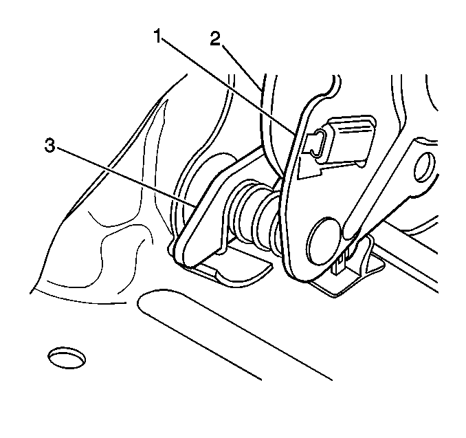
- Remove the cable barrel (3) from the lever reel (1).
- Remove the cable from the lever using the J 37043 .
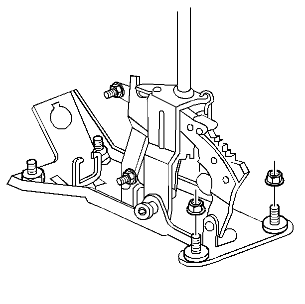
- Remove the shift assembly mounting nuts. Move the shiftier assembly out of the way just enough to allow the park brake assembly to be removed.
- Remove the three parking brake lever assembly nuts (3).
- Remove the parking brake lever assembly (1).

Installation Procedure
- Ensure that the latch pawl is engaged and the cable tension is released.
- Install the parking brake indicator switch.
- Install the parking brake lever assembly (1) and the shiftier assembly.
- Install the mounting nuts.
- Install the parking brake cable (2) to the new parking brake lever assembly reel (1).
- Release the latch pawl.
- Fully apply and release the hand brake 4 to 6 times in order to activate the self adjust system.
- Install the center console. Refer to Front Floor Console Replacement in Instrument Panel, Gages and Console.


Notice: Use the correct fastener in the correct location. Replacement fasteners must be the correct part number for that application. Fasteners requiring replacement or fasteners requiring the use of thread locking compound or sealant are identified in the service procedure. Do not use paints, lubricants, or corrosion inhibitors on fasteners or fastener joint surfaces unless specified. These coatings affect fastener torque and joint clamping force and may damage the fastener. Use the correct tightening sequence and specifications when installing fasteners in order to avoid damage to parts and systems.
Tighten
Tighten the parking brake lever mounting nuts to 25 N·m
(18 lb ft).

Notice: Parking brake adjustment is not necessary. This is a self adjusting system and damage may result from attempting to adjust or modify this system in any way. It may be necessary to adjust the rear brakes to obtain the proper tension in the system.
