UPDATE-SEC.3D-REAR SUSPENSION AUX.SPRING/NEW SPRING TOOL

Models Affected: 1988-89 GRAND PRIX
REAR SUSPENSION AUXILIARY SPRING
The following rear suspension procedures should be used when servicing components that require the removal or installation of the rear suspension auxiliary spring. The rear suspension auxillary spring, and special tool required to service it, have been redesigned. This update applies to the following Service Manuals and pages:
Year Model Pages ---- ----- ----- 1988 Pontiac Grand Prix 3D-3, 3D-8 and 3D-10 1989 Pontiac Grand Prix Delete all reference to auxiliary spring
AUXILIARY SPRING
Procedure:
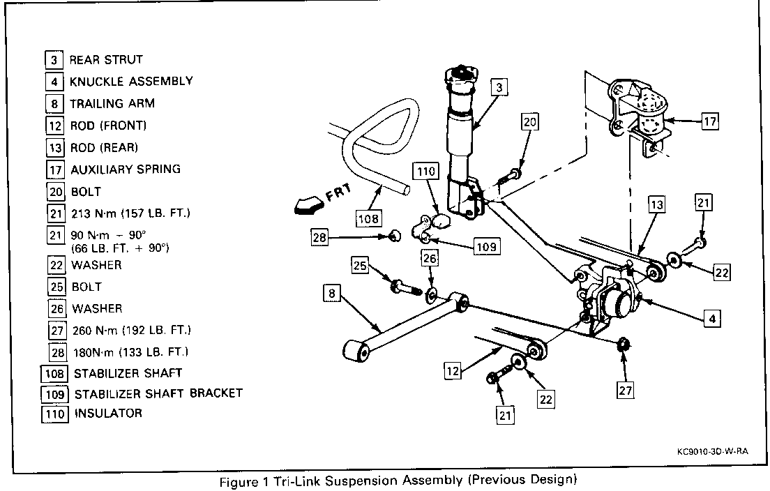
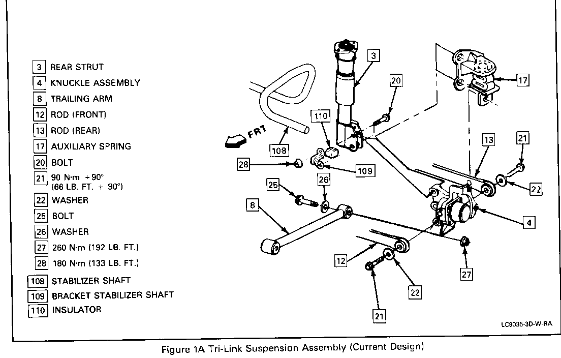
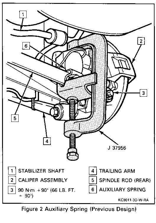
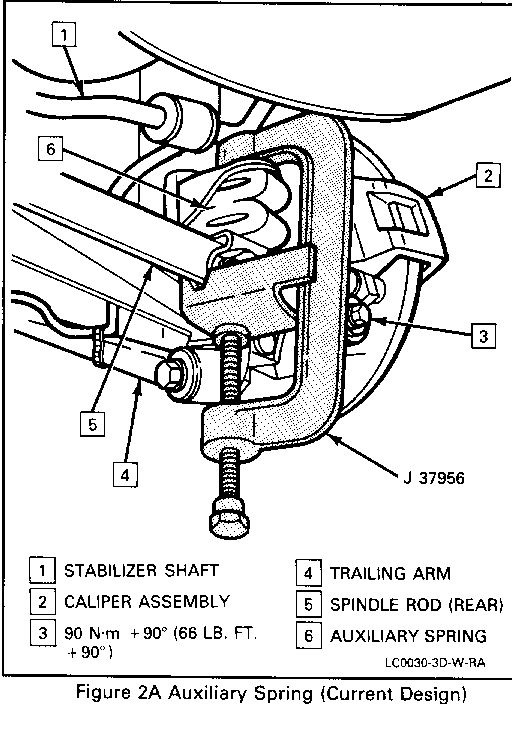
Figures 1, 1A, 2 AND 2A
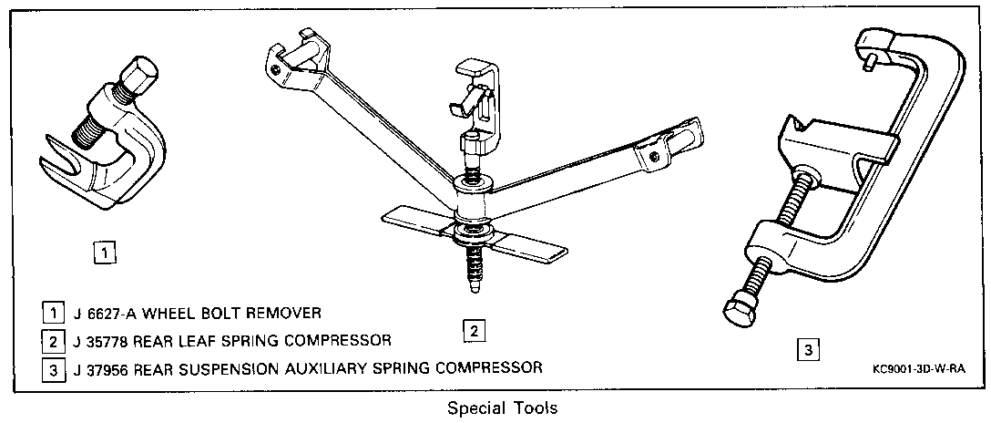
Tool Required: J 37956 Auxiliary Spring Compressor
REMOVE OR DISCONNECT
1. Raise vehicle, refer to General Information (SECTION OA).
2. Tires and wheels, refer to Tires and Wheels (Section 3E).
3. Leaf spring rear retention plate bolt.
4. Leaf spring front retention plate bolt just enough to rotate plate clear of rod.
5. Install J 37956 making certain pin in stationary end of clamp is inserted in hole of upper auxiliary spring bracket.
- Remove plug from upper bracket.
6. Seat rod in tool channel and hand tighten.
7. Rod to knuckle bolt.
8. Loosen J 37956 forcing screw to allow spring to expand.
IMPORTANT: When removing auxiliary spring, make sure that rod/bushing clears the transverse spring and boss on knuckle.
9. Auxiliary spring and J 37956.
INSTALL OR CONNECT
1. Auxiliary spring and J 37956.
2. Compress auxiliary spring using J 37956 enough to install rod to knuckle bolt.
IMPORTANT: Make certain pin in stationary end of clamp is inserted in hole of upper auxiliary spring bracket and rod is seated in tool channel.
When compressing auxiliary spring, make sure that rod/bushing clears the transverse spring and boss on knuckle.
3. Rod to knuckle bolt, using GM thread locker, P/N 1052624.
Tighten
- Bolt to 90 N.m + 90 degrees (66 lb. ft. + 90 degrees).
4. Remove J 37956 and reinstall plug.
5. Properly position retention plate and reinstall bolt.
Tighten
- Bolt to 20 N.m (15 lb. ft.).
6. Tires and wheels, refer to Tires and Wheels (Section 3E).
7. Lower vehicle.
UPPER AND LOWER AUXILIARY SPRING BRACKET
Figures 1, 1A, 2 and 2A
Tools Required: J 35778 Rear Leaf Spring Compressor J37956 Auxiliary Spring Compressor
REMOVE OR DISCONNECT
NOTICE: DO NOT USE SILICONE LUBRICANTS ON OR NEAR THE AUXILIARY SPRING. THESE MATERIALS MAY DAMAGE OR DETERIORATE RUBBER COMPONENTS.
1. Auxiliary spring using J 37956, refer to "Auxiliary Spring".
2. Scribe strut to knuckle.
3. Auxiliary spring lower bracket at rod.
4. Jack pad.
5. Install J 35778 to rear leaf spring.
- Fully compress rear leaf spring using J 35778, do not remove spring or retention plates.
6. Auxiliary spring upper bracket at strut/knuckle.
INSTALL OR CONNECT
1. Auxiliary spring upper bracket to strut/knuckle.
- Align scribe marks to ensure proper alignment.
Tighten
- Nuts to 180 N. m (133 lb. ft.)
2. Remove J 35778 from rear leaf spring.
3. Jack pad.
Tighten
- Bolts to 25 N.m (18 lb. ft.)
4. Auxiliary spring lower bracket to rod.
Tighten
- Nuts to 46 N.m (34 lb. ft.).
5. Auxiliary spring using J 37956, refer to "Auxiliary Spring".
STABILIZER SHAFT FRONT INSULATOR
Figures 1 and 1A
REMOVE OR DISCONNECT
1. Raise vehicle, refer to General Information (Section OA).
2. Scribe strut to knuckle.
3. Strut/upper auxiliary spring bracket/stabilizer shaft bracket nuts.
CAUTION:
LEAF SPRING IS UNDER HIGH TENSION. DO NOT REMOVE BOLTS AS PERSONAL INJURY COULD RESULT.
4. Pull insulator bracket from bolts.
5. Insulator from stabilizer shaft.
INSTALL OR CONNECT
1. Insulator to stabilizer shaft.
2. Strut/upper auxiliary spring bracket/stabilizer shaft bracket nuts.
- Align marks to ensure proper alignment.
Tighten
- Nuts to 180 N.m (133 lb. ft.)
3. Lower vehicle.
REAR ROD
REMOVE OR DISCONNECT
Tool Required: J 37956 Auxiliary Spring Compressor
1. Raise vehicle, refer to General Information (Section OA).
2. Tire and wheel assembly, refer to Tires and Wheels (Section 3E).
3. Auxiliary spring using J 37956, refer to "Auxiliary Spring".
4. Auxiliary spring lower bracket at rod.
5. Rod nut at crossmember.
6. Rear toe adjusting cam and push bolt forward enough to provide rod removal clearance.
7. Rod
INSTALL OR CONNECT
1. Rod
2. Push bolt rearward through rod bushing and install rear toe adjusting cam.
3. Rod nut at crossmember, and snug nut only.
- Do not tighten at this time.
4. Auxiliary spring lower bracket to rod.
Tighten
- Nut to 180 N.m (133 lb. ft.)
5. Auxiliary spring using J 37956, refer to "Auxiliary Spring".
6. Tire and wheel assembly, refer to Tires and Wheels (Section 3E).
7. Lower vehicle.
Adjust
- Toe, refer to Wheel Alignment (Section 3A).
Tighten
- Inboard rod to crossmember nut to 110 N.m + 60 degrees (81 lb. ft. + 60 degrees).
KNUCKLE ASSEMBLY
Figure 2 and 2A
Tool Required: J 35778 Rear Leaf Spring Compressor J 37956 Auxiliary Spring Compressor
REMOVE OR DISCONNECT
1. Raise vehicle, refer to General Information (Section OA).
2. Tire and wheel assembly, refer to Tires and Wheels (Section 3E).
3. Scribe strut to knuckle.
4. Jack pad.
5. Install J 35778 to rear leaf spring.
- Fully compress rear leaf spring with J 35778, do not remove leaf spring or retention plates.
6. Auxiliary spring using J 37956, refer to "Auxiliary Spring".
7. Front rod at knuckle.
8. Brake hose bracket, caliper, and rotor, refer to Disc Brake Caliper Assembly (Section 5B9).
9. ABS electrical harness, if ABS equipped.
10. Hub and bearing assembly.
11. Trailing arm from knuckle.
12. Strut/upper auxiliary spring bracket/stabilizer shaft bracket (if equipped) from knuckle.
13. Knuckle.
INSTALL OR CONNECT
1. Knuckle.
2. Strut/upper auxiliary spring bracket/stabilizer shaft bracket (if equipped) to knuckle.
- Hand start nuts only.
3. Front rod to knuckle and snug bolt.
- Use GM thread locker, P/N 1052624.
- Do not tighten bolt at this time.
4. Trailing arm to knuckle.
Tighten
- Nut to 260 N.m (192 lb. ft.).
5. Hub and bearing assembly.
6. ABS electrical harness, if removed.
7. Rotor and caliper, refer to Disc Brake Caliper Assembly (Section 5B9).
Tighten
- Align scribe marks to ensure proper wheel alignment.
- Strut to knuckle to upper auxiliary spring bracket to stabilizer shaft bolts to 180 N.m (133 lb. ft.)
8. Brake hose bracket, refer to Disc Brake Caliper Assembly (Section 5B9).
9. Auxiliary spring using J 37956, refer to "Auxiliary Spring".
Tighten
- Rod to knuckle bolts, using GM thread locker, P/N 1052624 to 90 N.m + 90 degrees (66 lb. ft. plus 90 degrees).
10. Remove J 35778 from rear leaf spring.
11. Jack pad.
Tighten
- Bolt to 25 N.m (18 lb. ft.)
12. Tire and wheel assembly, refer to Tires and Wheels (Section 3E).
13. Lower vehicle.
STRUT ASSEMBLY
Figures 1, 1A, 2 and 2A
REMOVE OR DISCONNECT
Tools Required: J 35778 Rear Leaf Spring Compressor J 37956 Auxiliary Spring Compressor
1. Raise vehicle, refer to General Information (Section OA).
2. Tire and Wheel assembly, refer to Tires and Wheels (Section 3E).
3. Scribe strut to knuckle.
4. Jack pad.
5. Install J 35778 to rear leaf spring.
- Fully compress rear leaf spring using J 35778, do not remove spring or retention plates.
6. Auxiliary spring using J 36956, refer to "Auxiliary Spring".
7. Brake hose bracket at strut.
8. Strut to body bolts.
9. Strut/auxiliary spring upper bracket/stabilizer shaft bracket from knuckle.
INSTALL OR CONNECT
1. Strut to body bolts.
Tighten
- Bolts to 46 N.m (34 LB. FT.).
2. Strut/upper auxiliary spring bracket/stabilzer shaft bracket to knuckle.
- Align scribe marks to ensure proper alignment.
3. Brake Hose Bracket.
4. Auxiliary spring using J 37956, refer to "Auxiliary Spring".
5. Remove J 35778 from rear leaf spring.
6. Jack pad.
Tighten
- Bolt to 25 N.M (18 LB. FT.)
7. Tire and wheel assembly, refer to tires and wheels (Section 3E).
8. Lower vehicle.
General Motors bulletins are intended for use by professional technicians, not a "do-it-yourselfer". They are written to inform those technicians of conditions that may occur on some vehicles, or to provide information that could assist in the proper service of a vehicle. Properly trained technicians have the equipment, tools, safety instructions and know-how to do a job properly and safely. If a condition is described, do not assume that the bulletin applies to your vehicle, or that your vehicle will have that condition. See a General Motors dealer servicing your brand of General Motors vehicle for information on whether your vehicle may benefit from the information.
