SERVICE MAN.UPDATE SEC.8A ELECT.DIAGNOSTIC REVISION

Subject: SERVICE MANUAL UPDATE-SECTION 8A-ELECTRICAL DIAGNOSIS/ (DIAGNOSTIC REVISIONS)
Models Affected: 1990 GRAND AM MODELS
This bulletin provides late production and revised information to supplement Section 8A.
The Update Change Summary follows the Service Manual Index. The Summaries show the minor wiring changes since publication of the final edition of the 1990 Service Manual.
All changes are labeled with a late production or revised note to help identify the type of revision.
Multi-Use Index allows the user to reference the Section 8A Supplement or 1990 Service Manual.
Please update your Service Manual accordingly.
INDEX
Service Manual Page/Revision Page and Category -------------- ------------- Air Conditioning Air Delivery Electronic ................68-0 Blower Controls Electronic ................66-0 Compressor Controls Electronic ................67-0 System Check ...................62-0 Alarms (Audible) Chime ..............76-0 Antenna (Power) ................. 151-0 Automatic Safety Belts ......146-0 Brake Warning System ..41-0 Charging System ..................30-1 Cigar Lighter .................... 114-4 Circuit Breaker Details ........10-0, 11-0, 10-0-A1, 10-2-A1, 10-53 Clock (Digital) ..................150-0 Component Location Views ........201-0 Connector (Harness Connector Faces) ........202-0 Coolant Fan ...................... 31-0 Cruise Control ..................34-0 34-23, 34-43, 34-233 Defogger (Rear) ...................61-0 Digital Clock .....................150-0 Door Locks (Power) .......130-0 Engine Control Electronic Fuel Injection (VIN U) ..................... 20-0 Multi-Port Fuel Injection (VIN N) ..................... 21-0 Multi-Port Fuel Injection (VIN D) ..................... 23-0 Fuel Gage Indicators Cluster .....80-0 Fuse Block Details .....11-0 11-33 Fuse Details ................. 10-0, 11-0 10-0-A1, 10-2-A1, 10-53 11-33 Fusible Link Details......... 10-0 10-0-A1, 10-2-A2, 10-53 Gages Indicators Cluster ............80-0 Fuel ........................80-0 Speedometer ...........80-2 Ground Distribution ...............14-0 14-0-A1, 14-43 Harness Routing Views............ 203-0 Heater .........................60-0 Horns ..........................40-0 Indicators Digital Cluster ................82-0 Standard Cluster .........80-0 Brake ....................80-0 Coolant Temperature 80-3 Cr-uise ....................80-1 Fasten Belts ................80-2 Hi Beam ............80-2 LH Turn ............80-2 Low Coolant .....80-0 Oil Pressure ................80-1 RH Turn ............80-2 Service Engine Soon 80-0 Turn Lights On ..............80-3 Volts ....................80-0 Instrument Panel Standard Cluster ........80-0 Interior Lights Dimming 117-0 Introduction .....2-0 Lights (Exterior) Back Up ...........112-0 Daytime Running ............... 104-0 104-0-A1, 104-4-A1 Front Marker .................. 110-0 110-1-A1 Hazard .....................110-0 110-0-A1 Headlights .....................100-0 100-03 License ....................110-2 110-23 Park .........................110-0 110-1-A1 Rear Marker ................... 110-2 110-23 Stop .........................110-0 110-0-A1 Tail .........................110-2 110-23 Turn .........................110-0 110-1-A1 Lights (Interior) Ashtray ......................117-1 Console Shift ............114-4 Courtesy ..............114-1 114-13 Dome With Quarter Courtesy........114-1 114-13 Without Quarter Courtesy.....114-0 114-13 Headlight Switch Assembly ......117-1 Heater and A/C Control Assembly .................117-1 Illuminated Entry ............114-3 Instrument Cluster .........117-1 I/P Compartment ............114-4 Luggage Compartment With Quarter Courtesy ..114-1 114-13 Without Quarter Courtesy.....114-0 114-03 PRNDL Illumination............ 117-1 Radio......................... 117-1 Underhood .................114-4 Vanity Mirror With Quarter Courtesy........114-1 114-13 Without Quarter Courtesy... 114-0 114-03 Wiper Switch Assembly.......... 117-1 Light Switch Details..............12-0 12-13 Luggage Compartment Lid Release ......................134-0 Power Antenna ................... 151-0 Power Distribution ............10-0 10-0-A1, 10-2-A1, 10-53 Power Door Locks................ 130-0 Power Seats .................... 140-0 Power Windows .................. 120-0 Radio .......................... 150-0 Rear Defogger ................... 61-0 Repair Procedures ...... 5-0 Safety Belts (Automatic) .. 146-0 Seats (Power) ....................140-0 Service Parts Information ........200-0 Speedometer Standard Cluster................80-2 Starter ...................30-0 Symbol........................... 3-0 Troubleshooting Procedures .........4-0 Vehicle Speed Sensor ............. 33-0 Warnings (Audible) Chime .................76-0 Windows (Power) ................. 120-0 Wiper/Washer Pulse ...................... 91-0 Standard ....................... 90-0
Update Change Summary
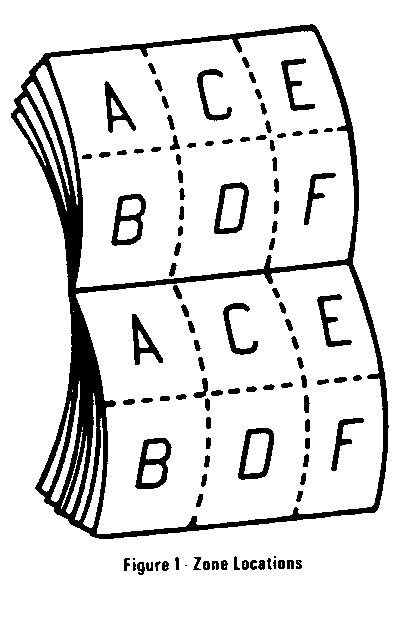
The Update Change Summary describes the revisions, the category of revision, the cell and page number, and the zone where the revision can be located on the schematic. The schematic is separated into six zones so that information can be easily and consistently located within Section 8A. Figure 1 below shows the zone locations. It is recommended that you transfer the minor change information into the Update Change Summary to your 1990 Service Manual.
Multi-Use index
The Multi-Use Index contains all information regarding the 1990 Service Manual plus all the information included in the Section 8A Supplement. This allows the user to enter the Section 8A Supplement or 1990 Service Manual by using just one index. Page numbers for the 1990 Service Manual are under the heading SERVICE MANUAL PAGE. Pages included in the Section 8A Supplement are highlighted in boldface type and page numbers are under the heading PAGE/REVISION AND CATEGORY. The number located to the upper right of the page number under the PAGE/REVISION AND CATEGORY column identifies the category of the revision. Note the Key located in the Index which defines what the individual numbers represent.
Late Production and Revised Notes
The Late Production and Revised notes are used throughout the Section 8A Supplement to identify the type of revisions that occurred during the model year. LATE PRODUCTION indicates that cars were built as shown in the Late Production revision as well as shown in the schematic in the respective 1990 Service Manual. Page numbers for Late Production schematics are noted in the Index and are in boldface type. Late Production schematics are identified by an "A " following the page number (example 4 2-0-A). The "A " indicates that there are two schematies that represent how the car was built. Using this example, 42-0-A shows the Late Production version and 42-0, in the 1990 Service Manual, shows another earlier version of how the car was built.
REVISED indicates that revisions occurred; however, the cars were built only in the way the Revised schematic represents. Revised schematics are noted in the Index with bold type, using the same page number used in the 1990 Service Manual. Note, a Revised schematic supersedes the respective page in the 1990 Service Manual.
UPDATE CHANGE SUMMARY
For details on how to use this cell, refer to Contents page.
Page Zone Revision Category
BA-10-5 A, C Late Production
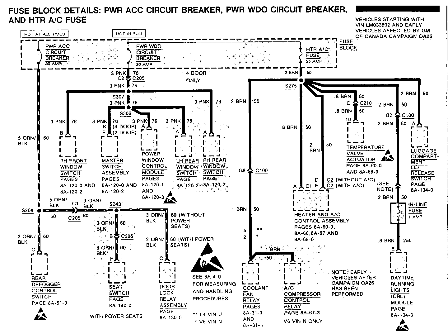
8A-11-3 E Late Production
BA-12-1 C, D, E Late Production
SA-14-4 A, E Late Production
SA-23-2 D Revised
SA-34-2 B Late Production
BA-34-4 D Late Production
BA-34-23 A Late Production
SA-100-0 B Late Production
BA-104-1 A, C Late Production
BA-110-2 C Late Production
BA-114-0 E Late Production
8A-114-1 E Late Production
Page Zone Revision
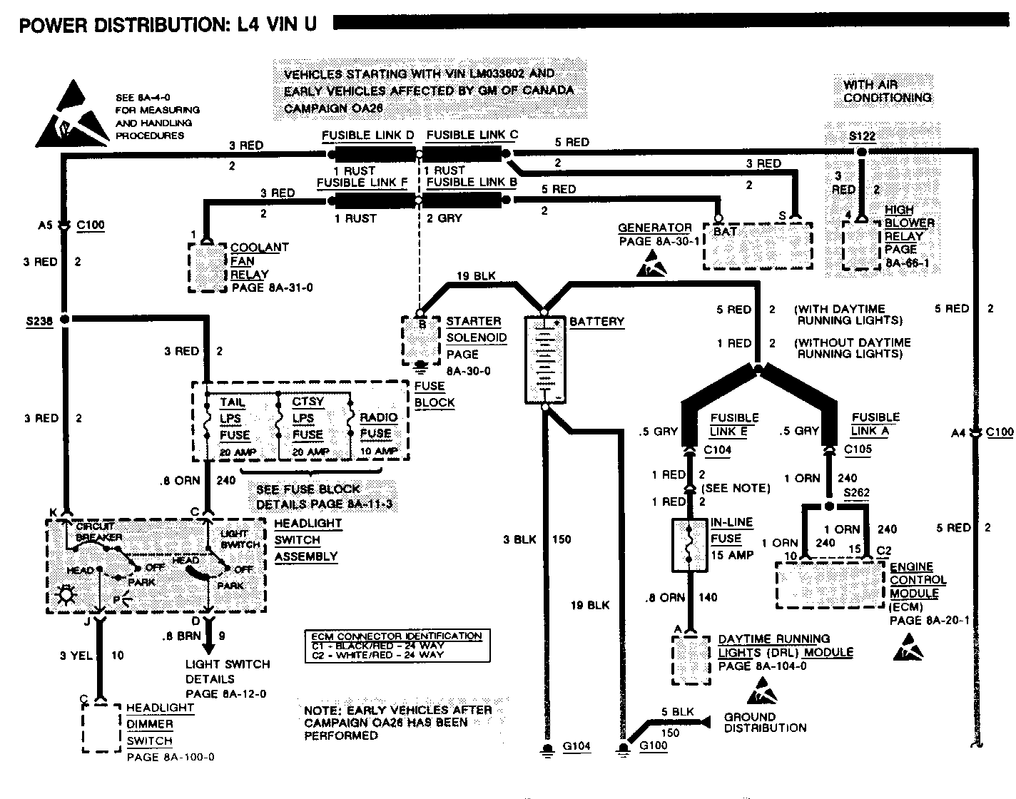
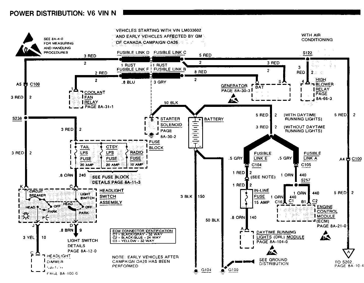
BA-10-5 A, C Add the following to the Component Location Chart: In-Line Fuse (1 Amp) ... LH front comer of engine compartment In-Line Fuse (15 Amp) ...... LH front corner of engine compartment
8A-11-3 E Change the .8 ORN (40) wire between connector C324/C and the Luggage Compartment Light to.8 ORN (340)
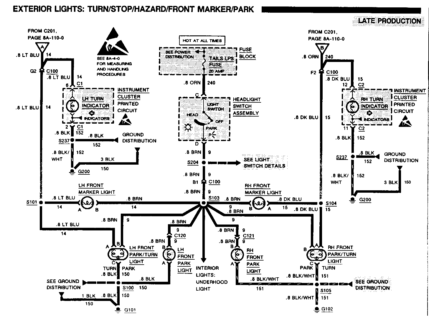
8A-12-1 C, D, E Add a 'B' at terminal of LH and RH Front Park/Tum Lights, LH and RH Front Park Lights, and LH and RH Tall/Stop-Tum Lights
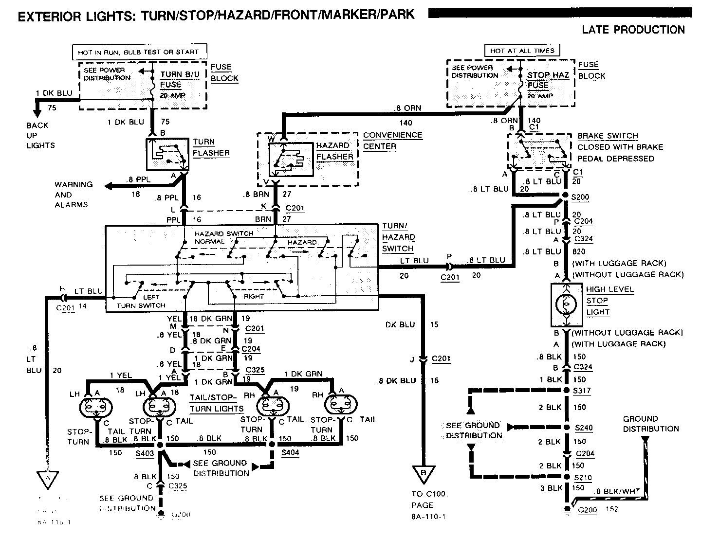
8A-14-4 A, E Add a 'C' at terminal of LH and RH Rear Tail/Stop-Turn Lights
8A-23-2 D Change the label above the Third Gear Switch from Switch Closes in Third Gear to Switch Opens in Third Gear
8A-34-2 B Change the.5 GRY/WHT (87) wire to.5 GRY/BLK (87)
8A-34-4 D See Update Change Summary page 8A-34-2
8A-34-23 A In A: Cruise Switch Short Test, change (GRY/VMT) to (GRY/BLK)
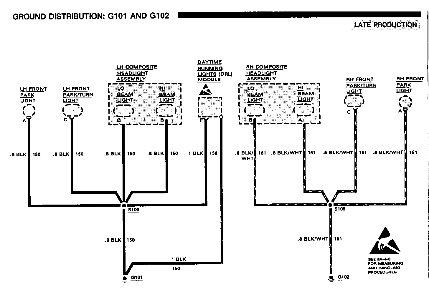
8A-100-0 B Add a BLK (150) wire between ground G101 and the reference See Ground Distribution
8A-104-1 A, C Add the following to the Component Location Chart: In-Line Fuse (1 Amp)... LH front comer of engine compartment In-Line Fuse (15 Amp)... LH front corner of engine compartment
8A-110-2 C Add a 'B' at .8 BRN (9) terminal of LH and RH Tall/Stop-Turn Lights Add 'C' at .8 BLK (150) terminal of LH and RH Tail/Stop-Turn Lights
8A-114-0 E See Update Change Summary page 8A-l 1-3
8A-114-1 E See Update Change Summary page 8A-1 1-3
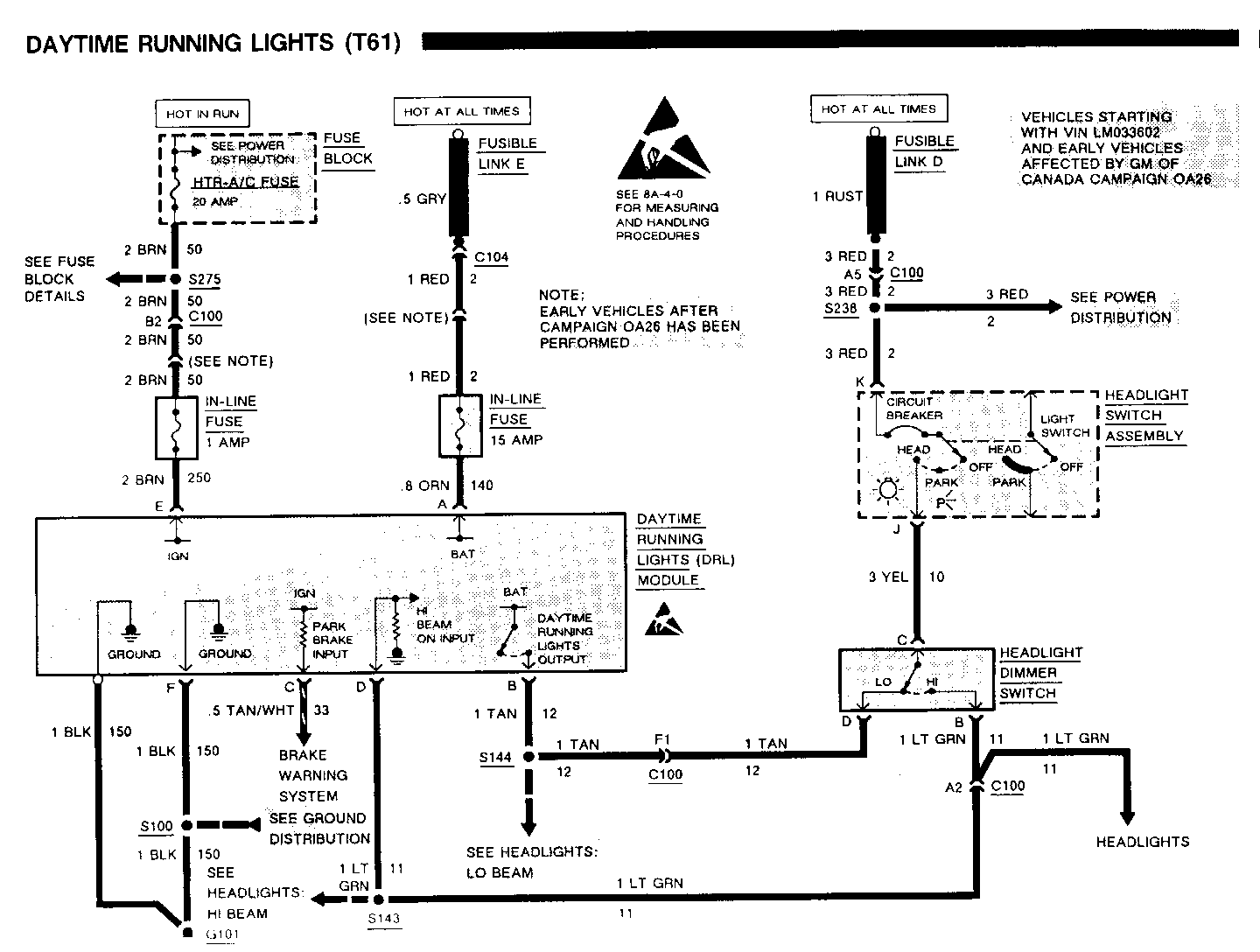
DAYTIME RUNNING LIGHTS (T61)
A: DAYTIME RUNNING LIGHTS (DRL) MODULE TEST (TABLE 1)
Measure: TEST LAMP At: DAYTIME RUNNING LIGHTS (DRL) MODULE CONNECTOR (Disconnected) Conditions: - Ignition Switch: RUN - Park Brake: Released - Light Switch: OFF
Connect Between Correct Result For Diagnosis ----------------- -------------- ---------------------------------- A (ORN) & Ground Lamp Lights Check/repair ORN (140) wire, In-line fuse, and RED wire for an open or short to ground (see schematic). E (BRN) & Ground Lamp Lights Check/repair BRN (250) wire, In-line Fuse, and BRN (50) wire for an open or short to ground (see schematic).
C (TAN/WHT) & Ground Lamp Lights See Brake Warning System, page 8A-41. A (ORN) & F(BLK) Lamp Lights Check/repair BLK (150) wire for an open. A (ORN) & DRL Case Lamp Lights Check/repair BLK (150) wire and Ground Wire (BLK) ground G101 for open.
- Headlight Switch: ON - Headlight Dimmer Switch; HI
D (LT GRN) & Ground Lamp lights Check/repair LT GRN wire for an open or short to ground. - Park Brake: Applied
C (TAN/WHT) & Ground Lamp off See Brake Warning System, page 8A-41. - If all voltages are correct go to table 2
General Motors bulletins are intended for use by professional technicians, not a "do-it-yourselfer". They are written to inform those technicians of conditions that may occur on some vehicles, or to provide information that could assist in the proper service of a vehicle. Properly trained technicians have the equipment, tools, safety instructions and know-how to do a job properly and safely. If a condition is described, do not assume that the bulletin applies to your vehicle, or that your vehicle will have that condition. See a General Motors dealer servicing your brand of General Motors vehicle for information on whether your vehicle may benefit from the information.
