POWER STEER. PUMP DR. PULLEY WOBBLE-LATERAL RUN-OUT

VEHICLES AFFECTED: 1990 L,N AND W CARS WITH 2.3 ENGINE
This bulletin is separated into two parts. Part I addresses 1990 Quad 4 power steering pump drive pulley wobble (condition, cause and correction). Part II revises the 1990 Service Manual procedure for power steering pump drive pulley removal and installation on the Quad 4 engine.
PART I
POWER STEERING PUMP DRIVE PULLEY WOBBLE
CONDITION: 1990 "N", "W" and "L" cars equipped with a 2.3L Quad 4 or High Output Quad 4 engine built prior to engine number D041139, were assembled with a second design power steering pump drive pulley. Some of these pulleys may exhibit a noticeable wobble (side-to- side movement) while the engine is running.
CAUSE: This condition is the result of greater than normal lateral run-out of the power steering pump drive pulley.
CORRECTION: This condition can be corrected by installing a first design power steering pump drive pulley, part number 22532167. The first design pulley has been reinstated in 1990 Quad 4 and High Output Quad 4 production effective with engine number D041139.
PARTS INFORMATION:
Parts are currently available from CANSPO.
PULLEY DESIGN IDENTIFICATION:
First Design - 1987 through 1989: Pulley has solid face (no holes) part number 24571208
Second Design - 1990: Pulley face has three (3) holes part number 22545412.
1990 N-W-L cars equipped with a Quad 4 engine assembled with the second design pulley that exhibit a wobble condition, can be corrected by the following service procedure.
SERVICE PROCEDURE:
Tools Required: J 24420-B Puller J 38343 Pulley Remover J 36015 Pulley Installer
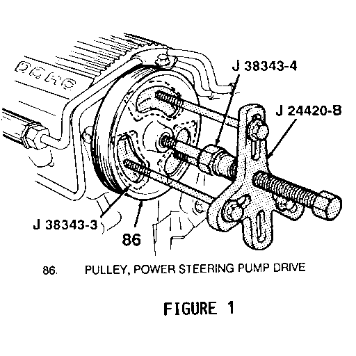
1. Position power steering pump aside to gain access to pulley. Refer to Figure 1.
2. Install forcing screw pilot J 38343-4 into pulley end of camshaft.
3. Install adapters J 38343-3 behind pulley one at a time while threading the 3/8" x 3-1/2" bolts included in J 38343 into them, through the holes in the pulley.
4. While holding J 38343-4 with a wrench, remove pulley with pulley remover J 38343.
5. Using tool J 36015 install new pulley, part number 22532167 onto end of intake camshaft.
6. Reposition and install power steering pump assembly, leaving adjustment bolts slightly loose.
7. Install power steering pump drive belt and tension as follows:
ADJUST BELT TENSION:
Tool Required: J 36018 Belt Tension Gauge
1. Place Gauge on belt.
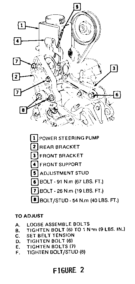
2. With pump adjusting bolts slightly loose, set belt tension to 500 newtons (110 pounds) by turning adjustment stud. Refer to Figure 2.
3. Tighten pump adjustment bolts to specifications noted in Figure 2.
PART II
Please update your 1990 Service Manual section 6A7 with the following information.
REVISED SERVICE MANUAL PROCEDURE, 1990 2.3L ENGINE, SECTION 6A7
1990 Quad 4 and High Output Quad 4 engines built prior to engine number, D041139 used a second design power steering pump drive pulley. It has been noted in some cases, that the second design pulley can exhibit greater than normal lateral run-out resulting in noticeable pulley wobble when the engine is running. To correct this condition in Production, the 1989 (first design) pulley was reinstalled on all 1990 Quad 4 and High Output Quad 4 engines effective with engine number D041139. Accordingly, if a second design power steering pump drive pulley is removed from a 1990 Quad 4 or High Output Quad 4 engine it should be replaced with the 1989 (first design) pulley, part number 22532167.
The following information replaces the power steering pump drive pulley removal and installation procedure on Pate 6A7-24 of the 1990 Cutlass Calais Service Manual, and Page 6A7-24 of the 1990 Cutlass Supreme Service Manuals.
SERVICE PROCEDURE:
Tools Required: J 38343 Pulley Remover (Second Design Pulley) J 29785-A Pulley Remover (First Design Pulley) J 36014-A Pulley Forcing Screw (First Design Pulley) J 36015 Pulley Installer
POWER STEERING PUMP DRIVE PULLEY REMOVAL - FIRST DESIGN PULLEY
1. Position power steering pump aside to gain access to pulley.
2. Using pulley remover, J 29785-A with forcing screw, J 36014-A remove pulley from end of camshaft.
POWER STEERING PUMP DRIVE PULLEY REMOVAL - SECOND DESIGN PULLEY
1. Position power steering pump aside to gain access to pulley. Refer to Figure 1.
2. Install forcing screw pilot J 38343-4 into pulley end of camshaft.
3. Install adapters J 38343-3 behind pulley one at a time while threading the 3/8" x 3-1/2" bolts included in J 38343 into them, through the holes in the pulley.
4. While holding J 38343-4 with a wrench, remove pulley with pulley remover J 38343.
INSTALLING POWER STEERING PUMP DRIVE PULLEY - FIRST DESIGN PULLEY
1. Using Tool J 36015 install pulley onto end of intake camshaft.
2. Reposition and install power steering pump assembly, leaving adjustment bolts slightly loose.
3. Install power steering pump drive belt and tension as follows:
ADJUSTING BELT TENSION:
Tool Required: J 36018 Belt Tension Gauge
1. Replace gauge on belt.
2. With pump adjustment bolts slightly loose, set belt tension to 500 newtons (110 pounds) by turning adjustment stud. Refer to Figure 2.
3. Tighten pump adjustment bolts to specification. Refer to Figure 2.


General Motors bulletins are intended for use by professional technicians, not a "do-it-yourselfer". They are written to inform those technicians of conditions that may occur on some vehicles, or to provide information that could assist in the proper service of a vehicle. Properly trained technicians have the equipment, tools, safety instructions and know-how to do a job properly and safely. If a condition is described, do not assume that the bulletin applies to your vehicle, or that your vehicle will have that condition. See a General Motors dealer servicing your brand of General Motors vehicle for information on whether your vehicle may benefit from the information.
