SERV. MANUAL UPDATE SEC.8B LIGHTING SYSTEM & HORNS

Subject: SERVICE MANUAL UPDATE - SECTION 8B LIGHTING SYSTEM AND HORNS (AIMING THE 55 X 135 MINI-QUAD HEADLAMP)
Models Affected: 1991 GRAND PRIX COUPE MODELS
General Description
No external aimer is required for the 55 X 135 mini-quad headlamp system unless the vehicle has been damaged in a collision.
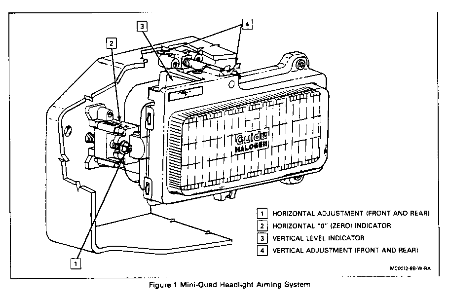
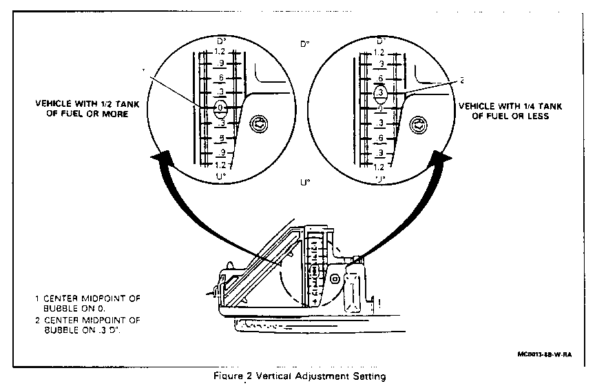
Vertical aim is accomplished by reading the level bubble with the vehicle sitting on a level surface and adjusting as needed. Horizontal aim has been factory preset and the indicator should point to "O" (Zero).
HEADLAMP REPLACEMENT (Coupe)
Remove or Disconnect
1. Open hood. 2. Raise headlamp access panel. 3. Electrical connector from headlamp. 4. Screw (1) from headlamp support panel. 5. Bottom screws (2) from headlamp frame. 6. Assembly, by lifting straight up.
- DO NOT apply pressure to plastic bubble of vertical aim indicator.
7. Screws (2) from headlamp retaining ring. 8. Rotate the headlamp retaining ring away from the headlamp. 9. Headlamp
Install or Connect
1. New headlamp 2. Screws (2) to headlamp retaining ring.
Tighten Screws to 2 N.m (18 lbs. in.)
3. Assembly Make sure two guide tabs drop into headlamp support panel
Tighten Bottom screws to 5 N.m (44 lbs. in.) Screw to headlamp support panel to 5 N.m (44 lbs. in.).
4. Electrical connector to headlamp. 5. Lower headlamp access panel. 6. Close hood
Inspect Vertical aim indicator bubble for correct headlamp aim.
Aiming
Normal Aiming
1. Prepare the vehicle:
a. Make sure all components are in place, if other service has been done to the vehicle.
b. Place the vehicle on a level surface.
IMPORTANT: Vehicle MUST be level. If necessary, pads may be used on uneven floors.
c. Stop all other work on the vehicle.
d. Close doors.
e. Rock vehicle sideways
NOTICE: HORIZONTAL AIM OF HEADLAMP MUST BE DONE FIRST. ADJUSTING VERTICAL AIM FIRST WILL RESULT IN INCORRECT HEADLAMP AIM.
2. Assure horizontal adjuster is set to "O" (Zero) mark:
a. If vehicle has been damaged, refer to "Aiming Headlamps After Collision" in this update.
b. If horizontal pointer is not set at "O" (Zero), turn the horizontal pointer aiming screw until pointer is lined up with "O".
3. Adjust the vertical aim by turning the vertical aiming screw until the bubble in the level is centered at "O" (Zero). If fuel tank is near empty to 1/4 full, adjust aim to center bubble at minus (-) .3 degrees. This will reduce the chance of raising the headlamps into oncoming driver's eyes when the fuel tank is filled.
Aiming Headlamp After A Collision
1. Prepare the vehicle.
A. Make sure all components are in place, if other service has been done to the vehicle.
B. Place the vehicle on a level surface.
IMPORTANT: Vehicle MUST be level, if necessary, pads may be used on uneven floors.
C. Stop all other work on the vehicle.
D. Close doors.
E. Rock vehicle sideways.
NOTICE: HORIZONTAL AIM OF HEADLAMP MUST BE DONE FIRST. ADJUSTING VERTICAL AIM FIRST WILL RESULT IN INCORRECT HEADLAMP AIM.
2. Headlamp aim may be accomplished using a wall and visual aiming as described in Motor Vehicle Manufacturers Association (M.V.M.A.) Vehicle Inspection Handbook, Section 5, "Lighting and Inspection", 1990 edition. (SEE ATTACHED)
3. It may be necessary to recalibrate the horizontal adjuster after a collision. This is done AFTER completion of the wall aiming procedure. Use a T-15 Torx screwdriver to reset the horizontal aim pointer to "O" (Zero).
PREPARATION & LIGHTING, GENERAL
Prior to a general lighting inspection, six preparatory steps should be taken, the first four of which should be the responsibility of the driver. If these are not accomplished to a reasonable degree, the inspector should refuse the vehicle until the preparation is satisfactory.
Prior To Preparation
1. Remove excessive ice and/or mud from under the fenders.
2. Inflate tires to specified pressures.
3. See that the vehicle contains no load other than the driver in his normal position.
4. Be sure the lenses are clean; check for burned out bulbs and proper beam switching. Headlamps with cracked or broken aiming pads, lenses, or visible moisture on interior should be replaced.
5. See that there is no faulty wheel alignment or improper tracking of the rear axle.
6. Check suspension. See that the vehicle does not lean to one side or the other. Rock the vehicle sideways to free and equalize suspension.
Advise Driver: That the operator of the vehicle should be responsible for the first four items. If the lamp is not a sealed beam headlamp and moisture is visible, advise driver that if condition continues for more than a few days, the lamp is not venting properly and the venting should be fixed or the headlamp replaced.
[X] Check Lamp Function Visually ---------------------------------- Procedure: Turn on night driving lights and check the following:
o Actuate turn signal lever right and left and observe function of tum signal lights and indicator lamps and the front cornering lamps (if so equipped).
o Place vehicle in reverse gear and check backup lamps (if vehicle is so equipped).
o If car is so equipped, actuate the following and observe lamps. Hazard warning lamps Indicator lamps Fog lamps
0 Observe function of: Stop lamps Headlamps - upper and lower beam Tail lamps Parking lamps Side marker lamps Reflex reflectors Clearance lamps Identification lamps Emergency warning lamps License plate lamp(s) All others
Reject Vehicle If:
o Any required lamp is missing.
o Any bulb or sealed beam unit fails to light.
o Turn signals do not properly indicate right and left when so switched.
o Back-up light system does not turn off automatically when vehicle goes forward.
o Lamp shows color contrary to law.
o Lamp fails to light the proper filament indicated at switch position.
o Any lamp or reflector does not direct light properly.
o Auxiliary equipment is placed on, in, or in front of any lamp (except original equipped headlamps with transparent covers).
o Lamp assembly improperly fastened.
o Lamp has a cracked, broken, or missing lens, or visible moisture on interior.
o Any headlamp fails to have the letters "DOT" horizontally or vertically on the lens.
o Any headlamp that has the word "motorcycle" on the lens.
WARNING:
Avoid touching or contacting the inner bulb in halogen headlights, halogen driving lamps, or the replaceable halogen headlamp bulb. Severe burns and damage to the bulb could result.
HEADLAMP AIMING - MECHANICAL METHOD
Vehicle must be located on a level area and loaded a it is normally driven with driver behind wheel. To ensure proper vehicle height for vehicles with active (load leveling) suspension systems, activate the air suspension system by operating the engine during the aiming inspection/adjustment and keep doors closed. U.S. headlamps are either "sealed beam" or "replaceable bulb" types.
Sealed Beam Headlamps
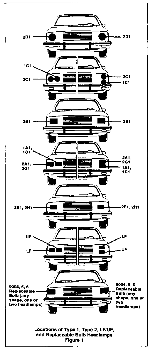
1. 177mm diameter, 2D1 both upper & lower beam.
2. 146mm diameter, 1C1 upper beam, 2C1 lower beam.
3. 142 x 200mm rectangular, 2BI both upper and lower beam.
4. 100 x 165mm rectangular, 1A1 and 1G1 upper beam, 2A1 and 2G1 lower beam and 2E1 and 2H1 both upper and lower beam.
5. 92 x 150mm rectangular, UF upper beam, LF lower beam
Replaceable Bulb Headlamp
1. 9004, 5, 6 Replaceable Bulb, both upper and lower beam (lamp lens may be marked with "HB1" to designate use of 9004 bulb).
2. 9005 and 9006 together, both upper and lower beam.
3. 9005 and 9006 in separate headlamps, upper and lower beam, respectively.
NOTE: Lamps with 9005 are marked "HB3" on lens, and lamps with 9006 are marked "HB4 " on lens. [X] High Beam (Type 1 or UF) or
Replaceable Bulb Type 9005 (HB1)
Equipment: Approved set of mechanical aimers. Calibrate mechanical aimer to "O" for vertical aim. Consult aimer instruction manual for procedure. (See page 29 for headlamp Aiming Information.)
Procedure: Attach mechanical aimer to headlamp in accordance with instructions. Take readings.
Reject Vehicle: If horizontal aim is more than: o 4 inches to the LEFT or o 4 inches to the RIGHT Vertical aim is:
o higher than 4 inches UP or o lower than 4 inches DOWN
[X] Low Beam Type 2, LF, or Replaceable Bulb Type 9004 (HB 1) or Type 9005 (HB3) and 9006 (HB4) Together
Equipment: Approved set of mechanical aimers. Calibrate mechanical aimer to "O" for vertical aim. Consult aimer instruction manual for procedure. (See page 29 for Headlamp Aiming Information.)
Procedure: Attach mechanical aimer to headlamp in accordance with instructions. Take readings.
Reject Vehicle: If horizontal aim is more than: o 4 inches to the LEFT or o 4 inches to the RIGHT
If vertical aim is: o higher than 4 inches UP or o lower than 4 inches DOWN
NOTE: All equipment for testing headlamps must comply with the Society of Automotive Engineers Recommended Practice For Headlamp Inspection Equip- ment. If a mechanical aimer is used, it should be in good repair and adjustment, and should be used according to the manufacturer's instructions and must be calibrated to the slope of the floor on which the vehicle stands.
HEADLAMP AIMING - SCREEN METHOD
Headlamp aiming by the screen method requires a level area in a darkened location, sufficient for the vehicle and an additional 25 feet from lamps to screen. The vehicle MUST be located accurately in front of the screen. Study HEADLAMP AIMING INFORMATION on page 29, for details about getting up this test properly.
[X] High Beam (Type 1 or UF, or Replacement Bulb Type 9005 (HB3) Used Above)
Equipment: Approve marked screen and adequate test area.
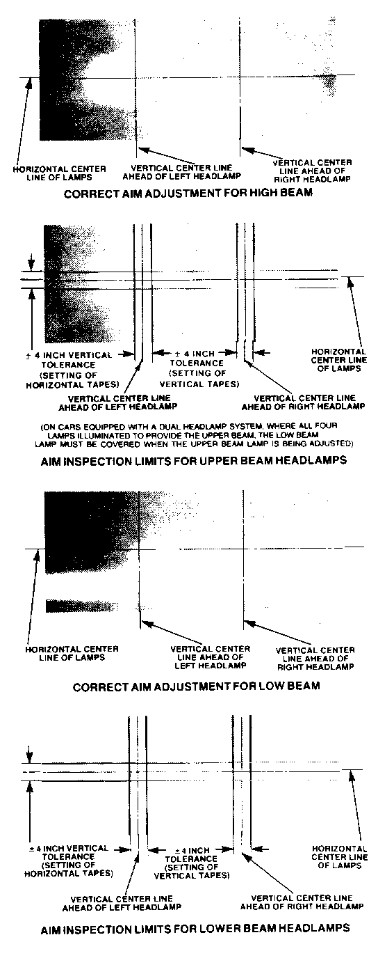
Procedure: With the vehicle properly located and loaded, switch headlamps to high beam and observe center of high intensity zone on the screen.
Reject Vehicle: If center is Horizontally: o More than 4 inches RIGHT o More than 4 inches LEFT of straight ahead
Center is Vertically: o More than 4 inches ABOVE or o More than 4 inches BELOW the horizontal line.
[X] Low Beam (Type 2, LF, or Replaceable Bulb, Type 9004 (HB1) or Type 9005 (HB3) and Type 9006 (HB4) Together)
Equipment: Market screen and adequate test area.
Procedure: With vehicle properly located and loaded, switch headlamps to low beam and observe left and top edges of high intensity zone on the screen.
Reject Vehicle: If left edge is Horizontally more than: o 4 inches 1,EFT or o 4 inches RIGHT of straight ahead
Top edge is Vertically more than: o 4 inches ABOVE or o 4 inches BELOW the horizontal line.
NOTE: ALWAYS inspect the following sealed beam and replaceable bulb headlamps on LOW BEAM only:
o 5"/4 inch, marked 2, 2C or 2C 1 o 7 inch, marked 2, 2D, or 2D I o 100 x 165mm rectangular, marked 2A, 2A1, 2E1, 2G1 or 2H1. o 200 x 142mm rectangular, marked 2B or 2BI o Replaceable Bulb Headlamps with 9004 (HB 1) o 92 x 150mm rectangular, marked LF o Replaceable bulb headlamps with 9006 (HB4) alone or in combination with 9005 (HB3).
FOG LAMP AIMING SCREEN METHOD
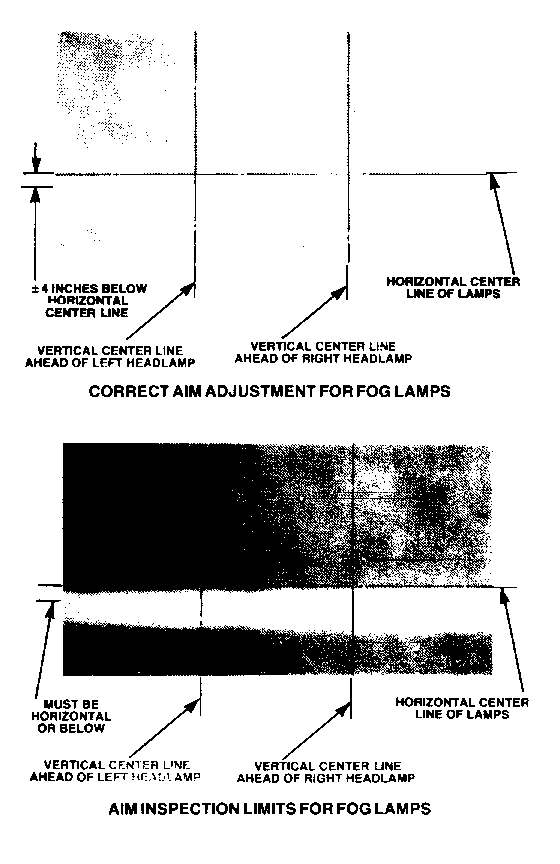
If a vehicle is equipped with fog lamps, they should be properly aimed. The movable horizontal and vertical lines on the aiming screen should be located so they cross at the "straight ahead" positions of the center-line of each fog lamp, whether symmetrical or non-symmetrical.
[X] Fog Lamp Inspection ------------------------ Procedure: With vehicle properly located and loaded (the same as for headlamp aim inspection) switch on the fog lamps and observe the location of the high intensity zone on the screen.
[X] Symmetrical Beam --------------------- Procedure: When properly aimed, the top edge of the high intensity zone is set 4 inches below horizontal centerline of fog lamp, and the center of the high intensity zone is set on the vertical centerline (see illustration).
Reject Vehicle: If center of high intensity zone is more than:
Horizontally- o 4 inches LEFT or o 4 inches RIGHT of straight ahead line, and
Top edge is: o Vertically ABOVE center line level.
[X] Non-Semmetrical Beam ------------------------- Procedure: When properly aimed, the top edge of the high intensity zone is set at the horizontal centerline of the fog lamp, and the left edge of the high intensity zone is set at the vertical centerline. (Same as low- beam Type 2 headlamps).
Reject Vehicle: If left edge of high intensity zone is: Horizontally more than:
o 4 inches LEFT of, or o 4 inches RIGHT of straight ahead line.
Top edge is: Vertically more than: ---------------------------------- o 4 inches ABOVE, or o 4 inches BELOW the horizontal line.
HEADLAMP AIMING INFORMATION
All equipment for testing headlamps must comply with the Society of Automotive Engineers Recommended Practice for Headlamps Inspection Equipment.
Mechanical Almer - if mechanical aimer is used, it shall be in good repair and adjustment, and shall be used according to the manufacturer's instruc- tions and must be calibrated to the slope of the floor on which the vehicle stands.
Headlamp Testing Machine - If a headlamp testing machine is used, it shall give results equivalent to those obtained using the screen procedure shown below. It shall be in good repair and adjustment, and shall be used in accordance with the manufacturer's instructions. The machine using a photo- electric cell or cells to determine aim should also have a visual screen upon which the beam pattern is projected proportional to its appearance and aim on a screen at 25 feet. Such visual screen shall be plainly visible to the operator and should have horizontal and vertical reference lines to permit visual appraisal of the lamp beam.
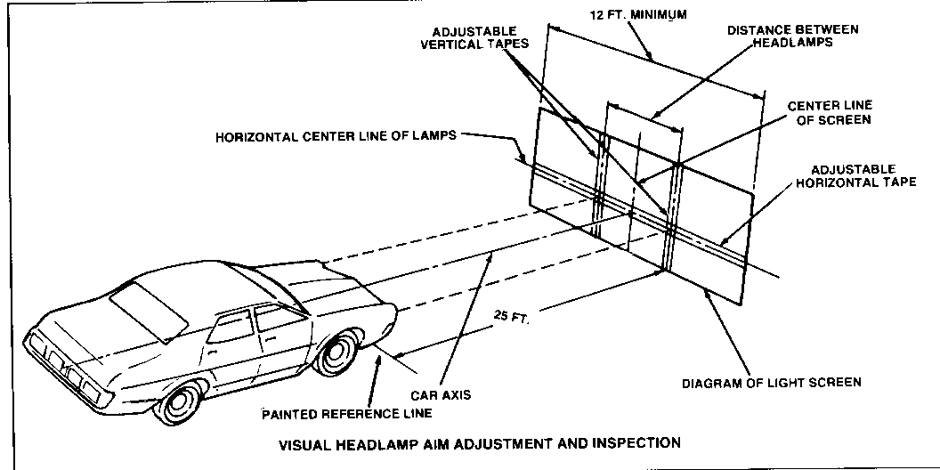
Headlamp Aiming by the Screen Method - First locate the vehicle so that it is square with the screen and with the front of the headlamps directly over a reference line which has been painted on the floor.
Next locate the center line on the aiming screen so that it is in line with the center of the vehicle. This can be done as shown below by sighting
through the center of the rear window of the vehicle and over the hood ornament - have vehicle moved until it is in alignment with these two points. If there is not center hood ornament. mark the center of the front and rear windows with narrow strips of masking tape. Use these "sights" to locate the center line of the aiming screen directly in line with the vehicle axis.
Aiming Area Required - It is desirable to have a specific aiming area in a darkened location. This should be sufficient for the vehicle and an addi- tional 25 feet measured from face of lamps to the front of the visual screen.
The floor on which the car rests must be flat, and level with the bottom of the screen. If the floor is not level, compensate.
Aiming Screen - If a screen is used, it should be 5' high x 12' wide with a matte white surface well shaded from extraneous light, and properly adjusted to the floor on which the vehicle stands. Provisions may be made for moving the screen so that it can be aligned parallel with the rear axle and so that a horizontal line drawn perpendicularly form the centerline of the screen will pass an equal distance midway between the two headlamps.
The screen shall be provided with a fixed vertical centerline, two laterally adjustable vertical tapes, and one vertically adjustable horizontal tape.
If a regular commercial aiming screen is not available, the screen may consist of a vertical wall having a clear uninterrupted area approximately 6 feet high and 12 feet wide.
The surface should be finished with a washable non-gloss white paint.
After the aiming screen has been set up in its permanent location, it is necessary to paint a reference line on the floor directly under the lens of the lamps to indicate the proper location of the headlamps when they are being aimed.
General Motors bulletins are intended for use by professional technicians, not a "do-it-yourselfer". They are written to inform those technicians of conditions that may occur on some vehicles, or to provide information that could assist in the proper service of a vehicle. Properly trained technicians have the equipment, tools, safety instructions and know-how to do a job properly and safely. If a condition is described, do not assume that the bulletin applies to your vehicle, or that your vehicle will have that condition. See a General Motors dealer servicing your brand of General Motors vehicle for information on whether your vehicle may benefit from the information.
