SERVICE MANUAL UPDATE-SEC. 8A 2 POSITION OIL PRESSURE GAGE

SUBJECT: SERVICE MANUAL UPDATE - SECTION 8A - ADDITIONAL INFORMATION FOR TWO POSITION OIL PRESSURE INDICATOR GAGE
MODELS AFFECTED: 1992 GRAND PRIX MODELS
Some 1992 Pontiac Grand Prix models were built with a standard Oil Pressure Gage and some models were built with a Two-Position oil Pressure Indicator. This bulletin provides the necessary diagnostic information for Two-Position Oil Pressure Indicator System Faults.
The indicator will point to low oil pressure with the ignition switch in "RUN" with the engine NOT running. When the engine is running, normal oil pressure opens the Oil Pressure Switch and the Indicator will move to mid-scale.
Please add the attached pages to Section 8A of the 1992 Grand Prix Service Manual.
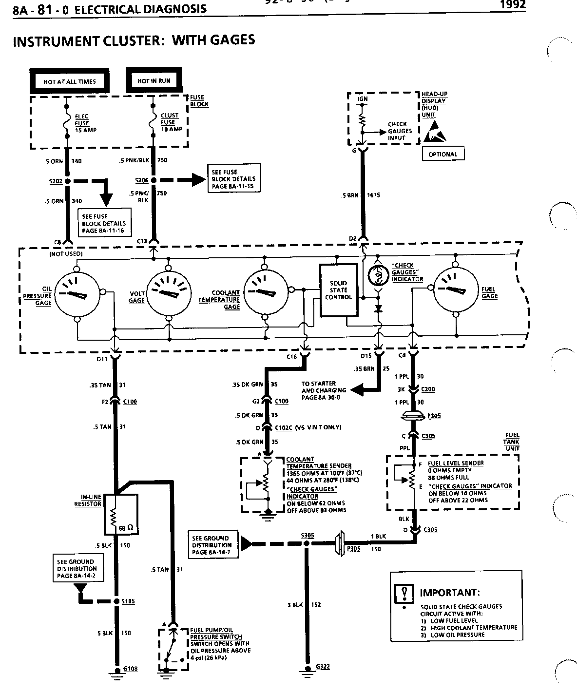
INSTRUMENT CLUSTER: WITH GAGES ------------------------------ COMPONENT LOCATION 201-PG FIG. CONN --------- -------- ------ ---- ---- Coolant Level Switch..... Top RH rear of radiator....... 8 .... 25 Coolant Temperature Sender (VIN T) ......... LH rear of Engine, below coolant outlet................ 4 .... 13 Coolant Temperature Sender (VIN X) ........ Lower LH front of Engine Electronic Ignition (EI) System ............ RH front of Engine, below Exhaust Manifold ............. 5 .... 17.. 202-41 Engine Control Module (ECM)............ RH side of Engine Compartment, forward of strut tower ...... 19 .... 68.. 202-24 Fuel Pump/Oil Pressure Switch (VIN T) (with Oil Cooler) ....... Lower LH front of Engine, below Oil Cooler ......... 19 ..... 69 Fuel Pump/Oil Pressure Switch (VIN T) (without Oil Cooler)..... Front center of Engine,near oil filter Fuel Pump/Oil Pressure Switch (VIN X) ......... Front center of Engine, near oil filter Fuel Tank Unit ......... Below rear of vehicle, top of fuel tank ........ 10 ..... 35 Fuse Block .............. RH side of I/P, in I/P Compartment Head-Up Display Unit...... Top LH side of I/P Oil Pressure In-line Engine Harn, approx 17 cm from Fuel Pump/Oil Resistor Pressure Switch C100 (36 cavities) ....... RH side of dash, behind strut tower ................................... 202-0 C102C (10 cavities) ...... RH front of Engine Compartment, near RS Electrical Center .................... 202-2 C200 (106 cavities) .......Behind RH side of I/P, near shroud .................... 2 ...... 8 ..202-5 C211 (8 cavities) ........ Behind I/P, on RH side of brake pedal support ........................... 202-37 C305 (6 cavities) ........ Center rear of vehicle, near front of fuel tank ... 10 ... 35...202-38 G103 ..................... LH front of Engine, on Transaxle stud ............ 0 .......1 G108 ..................... LH front of Engine, on Transaxle stud G119 ..................... LH strut tower ............ 2 .......7 G200 ..................... Behind I/P, on RH side of Steering Column support G322 ..................... Under RH front seat P100 ..................... LH rear of Engine Compartment, near strut tower ............ 2 ...... 7 P103 ..................... LH rear of Engine Compartment, near strut tower ...... .... 2 ...... 7 P305 ..................... Center front of Trunk, in floor S105 (VIN T) ............. Engine Harn, approx 4 cm from Electronic Ignition (EI) System breakout S106 (VIN T, VIN X) ...... Engine Harn, approx 20 cm from RS Electrical Center breakout S106 (VIN T GEN II S) .... Engine Harn, approx 20 cm from C100 breakout S125 ..................... Wiper Harn, approx 5 cm from Cruise Control Module breakout S202 ..................... I/P Harn, approx 4 cm from Radio breakout S206 ..................... I/P Harn, approx 30 cm from Fuse Block breakout ... ..... 15 ... 49 S209 ..................... I/P Harn, approx 12 cm from I/P Compartment Light breakout S211 ..................... I/P Harn, approx 7 cm from I/P Compartment Light breakout S213 ..................... I/P Harn, approx 18 cm from Fuse Block breakout S217 ..................... I/P Harn, approx 14 cm from Fuse Block breakout S305 ..................... Cross Car Harn, approx 5 cm from C305 breakout ..... 17 ... 61
INSTRUMENT CLUSTER: WITH GAGES ------------------------------ TROUBLESHOOTING HINTS (Perform before beginning System Diagnosis) --------------------- 1. Check CLUST Fuse. If open, check CKT 750 for short to ground.
2. Check INDIC Fuse. If open, check CKT 39 for short to ground.
3. Check any inoperative indicator bulb.
4. Make sure grounds G108, G119 and G200 are clean and tight.
- For Instrument Cluster Removal and Replacement procedures, refer to SECTION 8C.
- Check for a broken (or partially broken) wire inside of the insulation which could cause system failure but prove "GOOD" in a continuity/voltage check (see "Troubleshooting Procedures," page 8A-4-0)
- Check for proper installation of aftermarket electronic equipment which may affect the integrity of other systems (see "Troubleshooting Procedures," page 8A-4-0).
- Refer to System Diagnosis.
OIL PRESSURE INDICATOR GAGE DIAGNOSIS
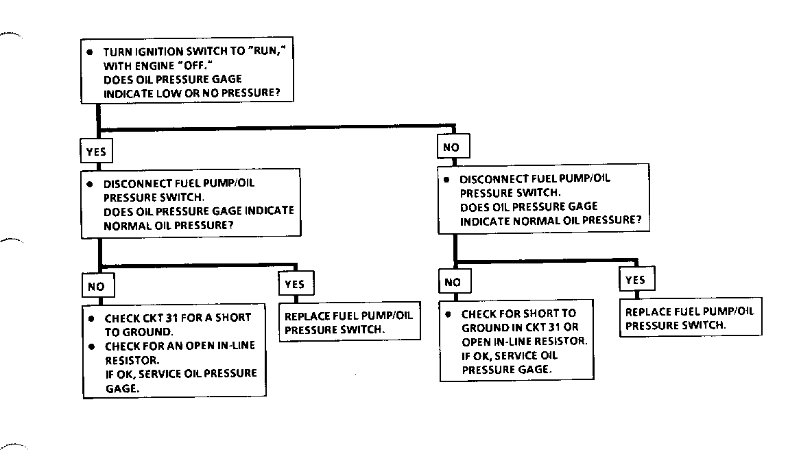
If the Oil Pressure Indicator stays "LOW" with the Engine running:
- Disconnect Fuel Pump/Oil Pressure Switch. If the indicator goes to normal, replace Switch. If the indicator stays "LOW," check CKT 31 for short to ground.
- Inspect the Instrument Cluster printed circuit for a short. Also check that the printed circuit is mating properly with its connectors and not shorted there.
If the Oil Pressure Indicator does not go to "LOW" before the Engine starts:
- Measure the resistance from the Fuel Pump/Oil Pressure Switch connector to ground. If the resistance is approximately 1 ohm, check CKT 31 for an open.
- Connect a fused jumper between Fuel Pump/Oil Pressure Switch connector terminal "B" and ground. If the indicator goes to "LOW," replace the Switch. If the indicator stays stays at normal, remove Instrument Cluster for service.
SYSTEM DIAGNOSIS
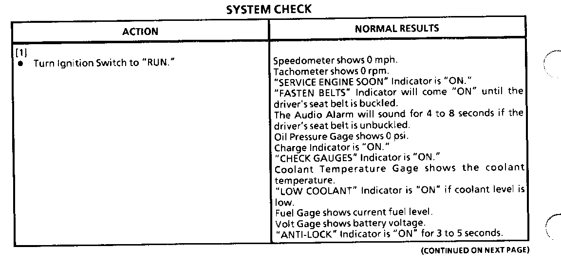
- Perform the System Check and refer to the Symptom Table for the appropriate diagnostic procedure(s).
INSTRUMENT CLUSTER: WITH GAGES ------------------------------ VOLT GAGE --------- The Volt Gage measures the electrical system's voltage with Ignition Switch in "RUN." With the Engine stopped, the Volt Gage indicates Battery condition. With the Engine running, the Volt Gage indicates Charging System operation.
SPEEDOMETER AND ODOMETER
The Vehicle Speed Sensor (VSS) generates a signal that indicates the speed of the solid state ECM to supply inputs to the Cruise Control Module, Speedometer and Odometer.
The Vehicle Speed Sensor is mounted in the Transaxle. A magnet rotates near a coil, producing voltage pulses in the coil. The frequency of the AC voltage coming from this coil depends on the vehicle speed. The VSS sends pulses to the ECM at the rate of 40,000 pulses per mile.
The ECM takes the voltage pulses from the sensor and uses them to close a solid state output switch. The output terminal is switched to ground at a rate that is proportional to the speed of the vehicle. The Speedometer and Odometer are switched at 4,000 pulses per mile.
"CHECK GAUGES" INDICATOR
The "CHECK GAUGES" Indicator is controlled by a Solid State buffer located in the Instrument Cluster. This buffer receives inputs from the Fuel Pump/Oil Pressure Sender/Switch, Coolant Temperature Sender, Fuel Level Sender and the Generator. When any of these components indicate that a gage is out of the normal operating range, the indicator control circuit grounds the "CHECK GAUGES" Indicator, causing it to light.
"LOW COOLANT" INDICATOR
The "LOW COOLANT" Indicator receives battery voltage with the Ignition Switch in "RUN," "BULB TEST" or "START." The indicator is grounded by the Coolant Level Switch with the coolant level in the Coolant Reservoir below a minimum recommended level.
OIL PRESSURE GAGE
Engine oil pressure is indicated by the Two Position Oil Pressure Gage. The pointer of the gage is moved by two coils, and its operation is similar to that of the Fuel Gage.
The Fuel Pump/Oil Pressure Switch is connected to the junction of the two coils. It opens above 4 psi, sending current through the In-Line Resistor to ground. This moves the pointer to the middle of the range, indicating normal oil pressure. A 68 ohm In-line Resistor keeps the indicator from going full scale with normal oil pressure.


General Motors bulletins are intended for use by professional technicians, not a "do-it-yourselfer". They are written to inform those technicians of conditions that may occur on some vehicles, or to provide information that could assist in the proper service of a vehicle. Properly trained technicians have the equipment, tools, safety instructions and know-how to do a job properly and safely. If a condition is described, do not assume that the bulletin applies to your vehicle, or that your vehicle will have that condition. See a General Motors dealer servicing your brand of General Motors vehicle for information on whether your vehicle may benefit from the information.
