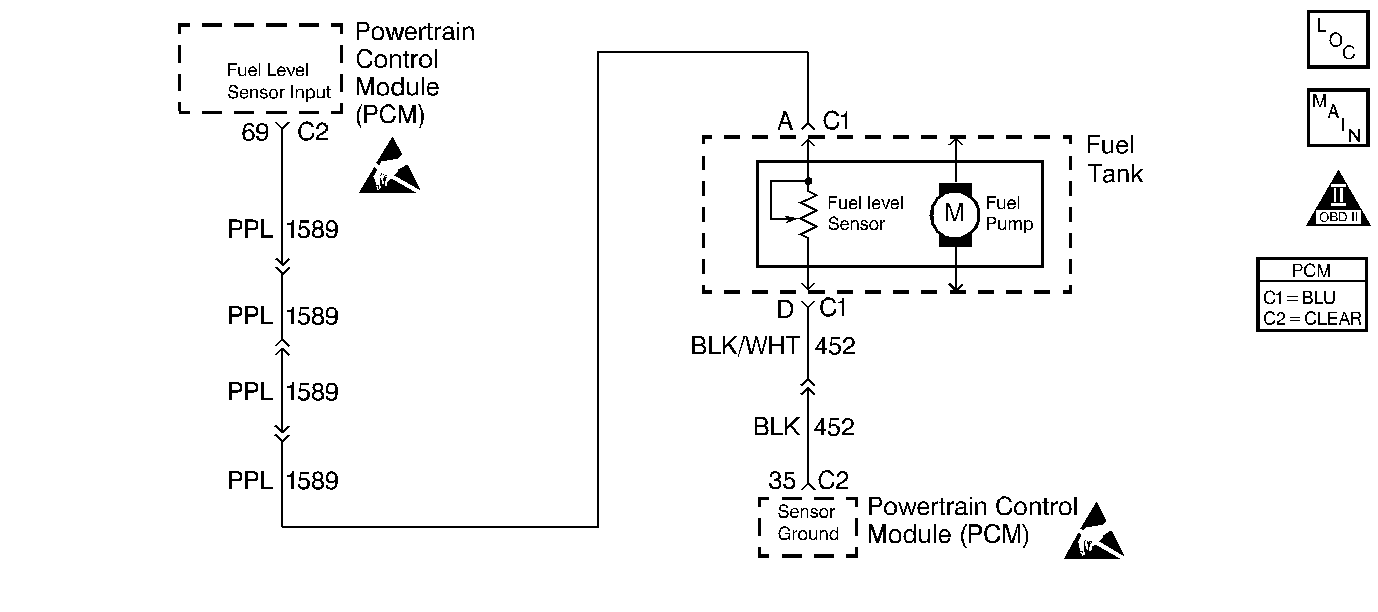
Circuit Description
The PCM supplies 5 volts to the fuel level sensor circuit. The fuel level sensor varies the voltage relative to the amount of fuel in the tank. The PCM monitors the voltage on the fuel level circuit to calculate the amount of fuel in the tank. The PCM uses the fuel level sensor information to control the fuel gauge via the fuel level output control circuit.
The PCM also uses fuel level information to enable the enhanced evaporative emission diagnostic.
Diagnostic Aids
Refer to Instrument Cluster System Check in Instrument Panel Gauges and Console for additional diagnostic information.
Check for the following condition(s):
Poor connections or damaged harness. Inspect the harness connectors for backed out terminals, improper mating, broken locks, improperly formed or damaged terminals, poor terminal to wire connection and damaged harness.
Test Description
Number(s) below refer to the step number(s) on the Diagnostic Table.
-
This checks for proper PCM voltage, ground and circuit wiring. The PCM supplies 5V to the fuel level sensor.
-
This checks for a fuel level sensor circuit shorted to battery positive.
-
This checks for a faulty fuel level sensor ground or splice connection.
Step | Action | Value(s) | Yes | No | ||||
|---|---|---|---|---|---|---|---|---|
1 | Was the Powertrain On-Board Diagnosis System Check performed? | -- | Go to the Powertrain OBD System Check | |||||
2 | Are there any other DTCs set? | -- | Diagnose the other DTCs first. | |||||
3 |
Does the fuel gauge indicate FULL? | -- | ||||||
4 |
Does the DMM display a voltage greater than the specified value? | 5V | ||||||
5 |
Is the test light ON? | -- | ||||||
6 |
Is the test light ON? | -- | ||||||
7 |
Does the fuel gauge indicate EMPTY? | -- | ||||||
8 |
Was a problem found? | -- | ||||||
9 |
Was a problem found? | -- | ||||||
10 | Locate and repair the short to voltage in the fuel level sensor feed circuit. Refer to Wiring Repairs in Wiring Systems.. Is action complete? | -- | -- | |||||
11 | Locate and repair the short to chassis or sensor ground. Refer to Wiring Repairs in Wiring Sytems. Is action complete? | -- | -- | |||||
12 | Replace the fuel level sensor. Refer to Fuel Level Sensor Replacement in Wiring Systems. Is action complete? | -- | -- | |||||
13 | Replace the PCM Important: Replacement PCM must be programmed. Refer to Powertrain Control Module Replacement/Programming . Is action complete? | -- | -- | |||||
14 | Recheck the system for proper operation. Does the system operate properly? | -- | System OK |
