For 1990-2009 cars only
Clutch Rotor and Bearing Removal V5- Direct Mount
Tools Required
| • | J 41790-A Compressor Holding Fixture |
| • | J 41552 Compressor Pulley Puller |
| • | J 33023-A Puller Pilot |
- Install the compressor onto the J 41790-A .
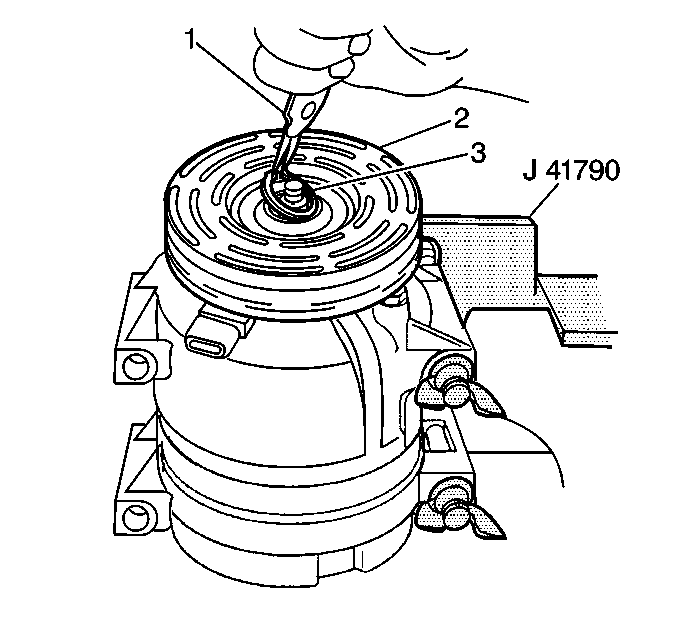
- Remove the clutch plate and hub assembly (2).
- Remove the clutch rotor and bearing assembly retaining ring (3), using external snap ring pliers (1).
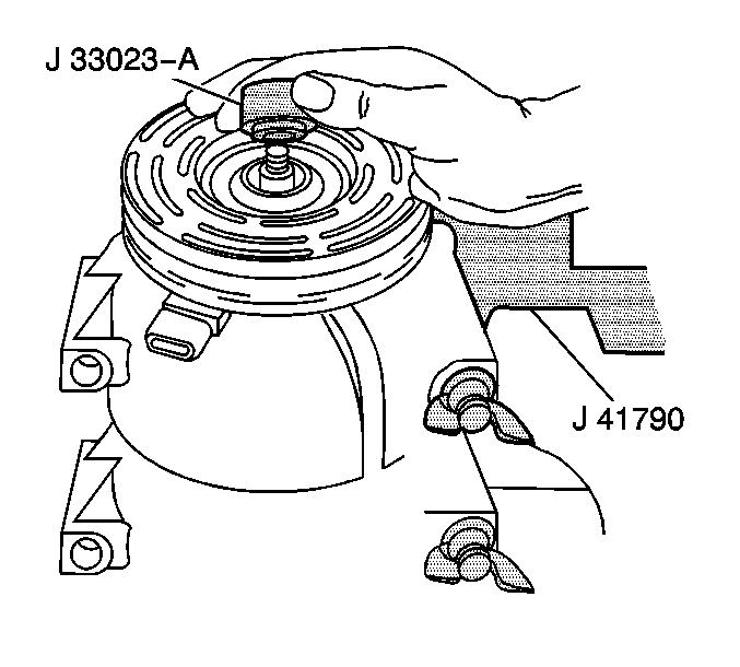
- Place the J 33023-A on the clutch rotor.
- Install the J 41552 down into the inner circle of slots in the rotor.
- Hold the compressor pulley puller in place and use a wrench to turn the center forcing screw against the puller pilot to remove the clutch rotor and bearing assembly.
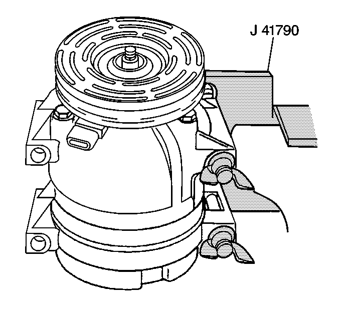
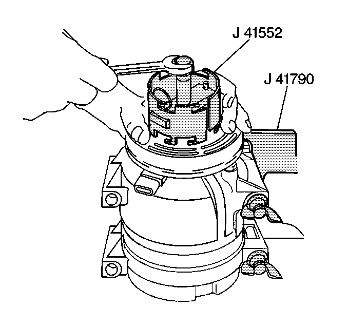
Turn the compressor pulley puller clockwise in the slots to engage the puller tangs with the rotor.
Clutch Rotor and Bearing Removal V5 - Conventional Mount
Tools Required
| • | J 6083 Snap Ring Pliers |
| • | J 9398 Bearing Remover |
| • | J 8092 Driver Handle |
| • | J 33020 Pulley Puller |
| • | J 33023-A Puller Pilot |
- Remove the clutch plate and hub assembly. Refer to Compressor Clutch Plate and Hub Assembly Removal (V5 - Conventional Mount) .
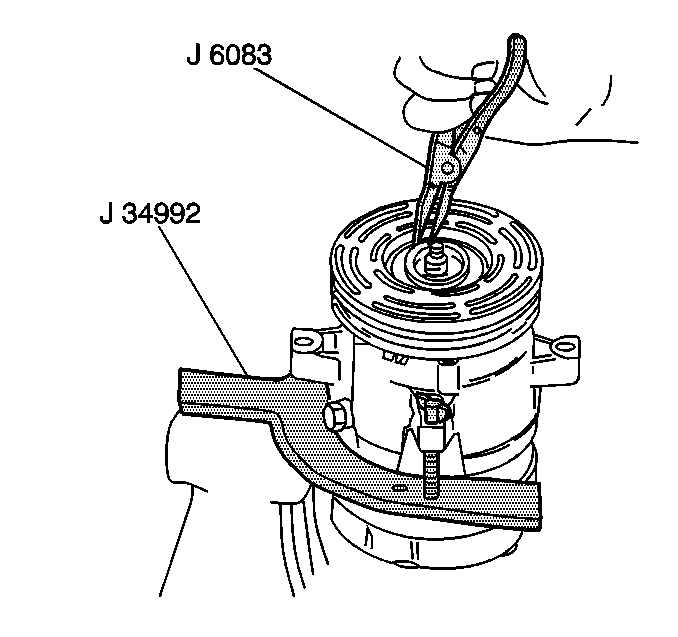
- Use the J 6083 in order to remove the rotor and bearing assembly retaining ring.
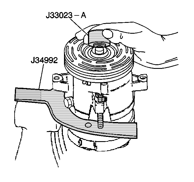
- Install the J 33023-A to the front head.
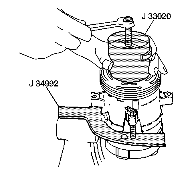
- Install the J 33020 into the inner circle of slots in the rotor.
- Turn the J 33020 clockwise in the slots in order to engage the tangs of the puller with the segments between the slots in the rotor.
- Hold the J 33020 in place. Tighten the puller screw against the puller guide in order to remove the puller rotor and bearing assembly.
- Support the rotor hub in order to prevent damage to the pulley rotor during bearing removal.
- Use a J 9398 with the J 8092 in order to drive the bearing out of the rotor hub.
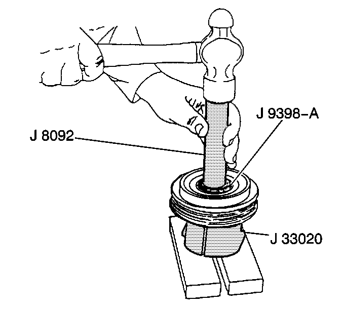
| 7.1. | Remove the forcing screw from the J 33020 . |
| 7.2. | With the tangs of the J 33020 still engaged in the rotor slots, invert the assembly onto a solid, flat surface or blocks. |
Notice: It is not necessary to remove the staking in front of the bearing to remove the bearing, however, it will be necessary to file away the old stake metal for proper clearance for the new bearing to be installed into the rotor bore or the bearing may be damaged.
