Special Tools
| • | J 28467-90A Engine Support Adapters |
| • | J 28467-B Universal Engine Support Fixture |
| • | J 36462-A Engine Support Adapter Leg Set |
Removal Procedure
- Disconnect the battery ground (negative) cable. Refer to Battery Negative Cable Disconnection and Connection in Engine Electrical.
- Carefully disconnect the throttle body air inlet duct.
- Remove the engine mount struts from the engine. Refer to Engine Mount Strut Replacement and Engine Mount Strut Replacement.
- Remove the drive belt. Refer to Drive Belt Replacement.
- Install the J 28467-90A , the J 28467-B , and the J 36462-A . Refer to Engine Support Fixture .
- Raise and suitably support the vehicle. Refer to Lifting and Jacking the Vehicle in General Information.
- Disconnect the three-way catalytic converter pipe from the right exhaust manifold. Refer to Catalytic Converter Replacement in Engine Exhaust.
- Remove the right front tire and wheel. Refer to Wheel Removal in Tires and Wheels.
- Remove the right engine splash shield. Refer to Engine Splash Shield Replacement in Body Front End.
- Drain the engine oil. Refer to Engine Oil and Oil Filter Replacement.
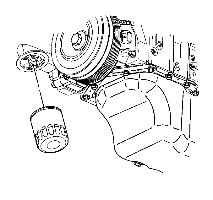
- Remove the oil filter. Refer to Engine Oil and Oil Filter Replacement.
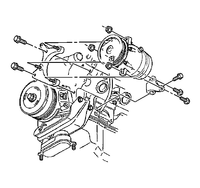
- Remove the A/C compressor bracket bolts. Reposition and secure the A/C compressor.
- Disconnect the power steering oil cooler pipe brackets from the frame.
- Remove the engine mount bracket bolts from the engine. Refer to Engine Mount Bracket Replacement.
- Remove the lower engine mount nuts. Refer to Engine Mount Replacement.
- Remove the torque converter cover. Refer to Torque Converter Cover Replacement in Automatic Transaxle - 4T65-E.
- Disconnect the oil level sensor wiring harness connector.
- Remove the oil level sensor.
- Lower the vehicle.
- Use the J 28467-B in order to raise the engine for access.
- Raise and suitably support the vehicle. Refer to Lifting and Jacking the Vehicle in General Information.
- Suitably support the frame. Loosen the left side frame bolts. Remove the right side frame bolts. Lower the frame for access.
- Remove the engine mount and the engine mount bracket.
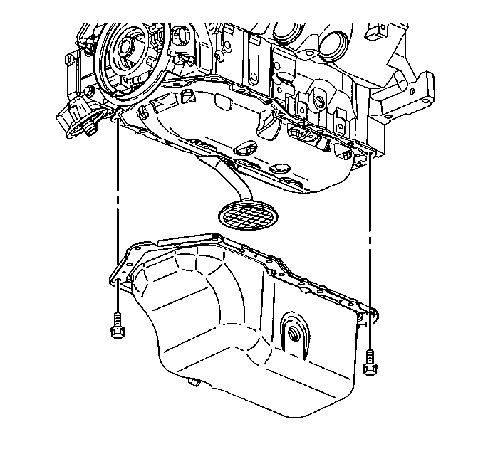
- Remove the oil pan retaining bolts.
- Lower the oil pan.
- Remove the oil pan.
- Remove the oil pump pipe and screen assembly and the oil pan gasket.
- Clean the following parts:
Important: Do not raise the engine.
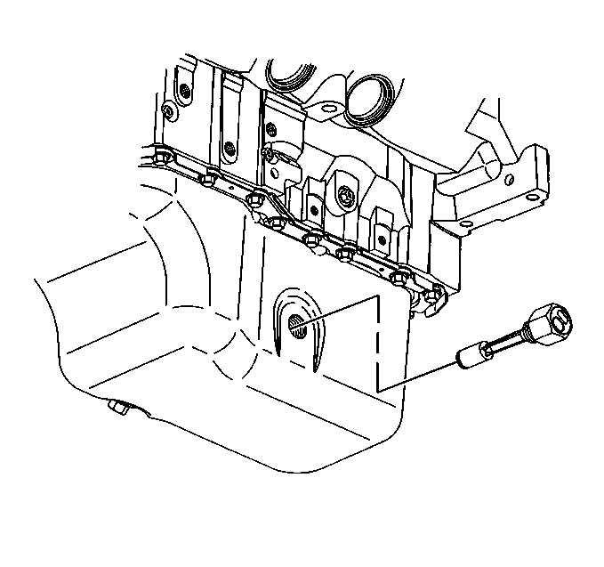
Notice: Remove the oil level sensor, located in the oil pan, before the oil pan is removed. The sensor may be damaged if the oil pan is removed first.
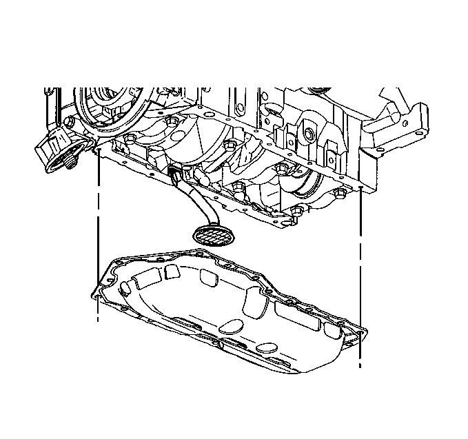
| • | The oil pan flanges |
| • | The oil pan rail |
| • | The front cover |
| • | The rear main bearing cap |
| • | The threaded holes |
Installation Procedure
- Apply a continuous bead 6.35 mm (0.25 in) thick of RTV sealer GM P/N 12378521 (Canadian P/N 88901148) to the topside of the new gasket. Apply the RTV sealant directly over the gaskets sealing bead.
- Install the NEW oil pan gasket onto the engine.
- Apply a continuous bead 6.35 mm (0.25 in) thick of RTV sealer GM P/N 12378521 (Canadian P/N 88901148) to the bottom side of the new gasket. Apply the RTV sealant directly over the gaskets sealing bead.
- Install the oil pan gasket and the oil pump pipe and screen assembly.
- Install the oil pan.
- Clean the oil pan bolts. Apply one drop of thread lock compound GM P/N 12345382, or the equivalent, to the oil pan bolt threads.
- Install the oil pan bolts.
- Place the engine mount bracket and the engine mount to the proper position. Install the engine mount bracket bolts to the engine. Refer to Engine Mount Bracket Replacement.
- Install new right side frame bolts. Ensure that the frame is suitably supported. Install new left side frame bolts. Refer to Frame Removal in Frame and Underbody.
- Lower the vehicle.
- Use the J 28467-B in order to lower the engine.
- Raise and suitably support the vehicle. Refer to Lifting and Jacking the Vehicle in General Information.
- Install the lower engine mount nuts.
- Install the oil level sensor.
- Connect the oil level sensor wiring harness connector.
- Install the torque converter cover. Refer to Torque Converter Cover Replacement in Automatic Transaxle - 4T65-E.
- Connect the power steering oil cooler pipe brackets to the frame.
- Install the A/C compressor bracket bolts. Refer to Compressor Replacement (3.8L) in HVAC System - Manual.
- Install the new oil filter. Refer to Engine Oil and Oil Filter Replacement.
- Install the oil pan bolt.
- Install the right engine splash shield. Refer to Engine Splash Shield Replacement in Body Front End.
- Install the right front tire and wheel. Refer to Wheel Installation in Tires and Wheels.
- Connect the three-way catalytic converter pipe to the right exhaust manifold. Refer to Catalytic Converter Replacement in Engine Exhaust.
- Lower the vehicle.
- Remove the J 28467-B , the J 36462-A , and the J 28467-90A .
- Install the drive belt. Refer to Drive Belt Replacement.
- Install the engine mount struts to the engine. Refer to Engine Mount Strut Replacement and Engine Mount Strut Replacement.
- Carefully install the throttle body air inlet duct.
- Fill the crankcase with new engine oil. Refer to Engine Oil and Oil Filter Replacement.
- Connect the battery ground (negative) cable. Refer to Battery Negative Cable Disconnection and Connection in Engine Electrical.
- Inspect for the proper fluid levels.
- Inspect for leaks.
- Measure the wheel alignment. Refer to Wheel Alignment Specifications and Wheel Alignment Measurement in Wheel Alignment.
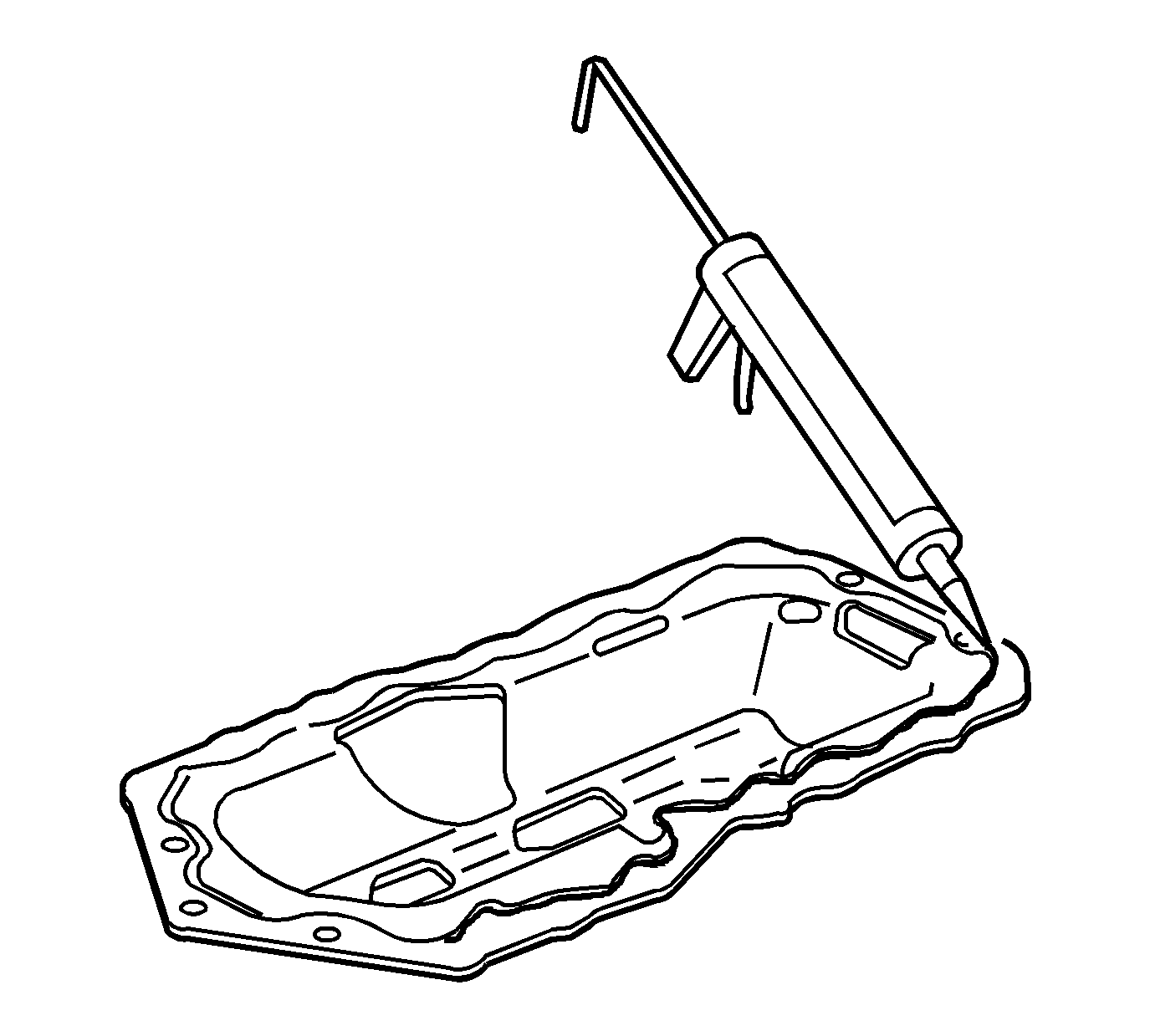
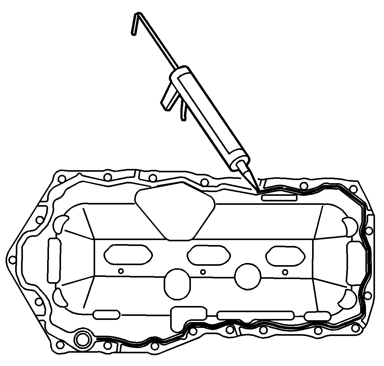

Notice: Install the oil level sensor, located in the oil pan, after the oil pan is installed. The sensor may be damaged if the oil level sensor is installed first.
Notice: Use the correct fastener in the correct location. Replacement fasteners must be the correct part number for that application. Fasteners requiring replacement or fasteners requiring the use of thread locking compound or sealant are identified in the service procedure. Do not use paints, lubricants, or corrosion inhibitors on fasteners or fastener joint surfaces unless specified. These coatings affect fastener torque and joint clamping force and may damage the fastener. Use the correct tightening sequence and specifications when installing fasteners in order to avoid damage to parts and systems.
Tighten
Tighten the oil pump pipe and screen bolts to 15 N·m (11 lb ft).

Important: Do not overtighten bolts. Damage to the oil pan may occur, resulting in an oil leak.
Tighten
Tighten the oil pan bolts to 14 N·m (125 lb in).
Tighten
Tighten the lower engine mount nuts to 47 N·m (35 lb ft).

Tighten
Tighten the oil level sensor to 20 N·m (15 lb ft).


