Circuit Description
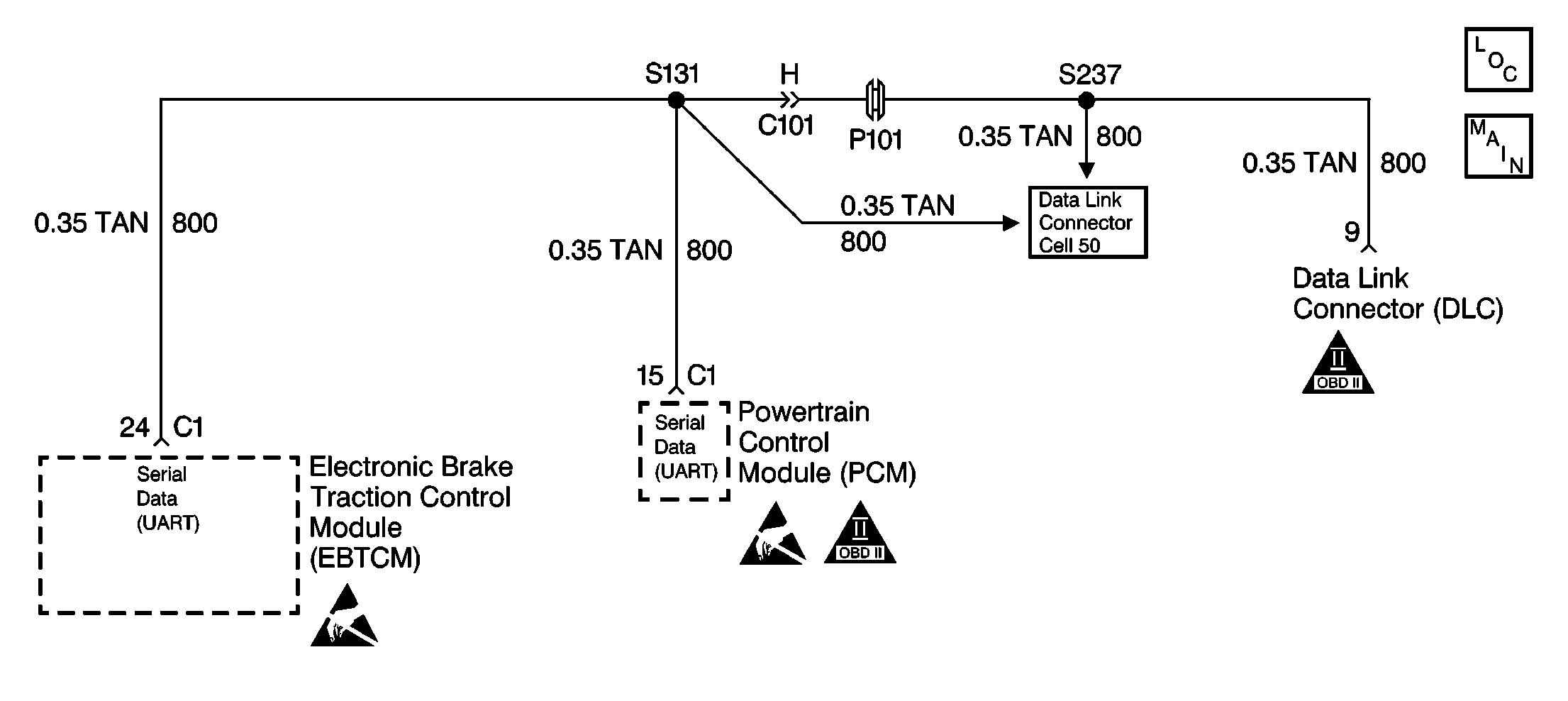
The UART serial data line allows information to be exchanged from module to module as needed. This is done by the PCM, the PCM requests and sends all the information that is transmitted on the UART line.
Conditions for Setting the DTC
DTC U1304 can be set anytime the ignition is in the RUN position and the EBTCM does not receive a $90 message from the PCM for 6 seconds.
Action Taken When the DTC Sets
| • | A malfunction DTC stores. |
| • | The TCS is disabled. |
| • | The amber TCS indicator is turned on. |
Conditions for Clearing the DTC
| • | The condition responsible for setting the DTC no longer exists and the scan tool Clear DTCs function is used. |
| • | 100 ignition cycles pass with no DTC(s) detected. |
Diagnostic Aids
| • | It is very important that a thorough inspection of the wiring and connectors be performed. Failure to carefully and fully inspect wiring and connectors may result in misdiagnosis, causing part replacement with reappearance of the malfunction. |
| • | Thoroughly inspect any circuitry that may be causing the complaint for the following conditions: |
| - | Backed out terminals |
| - | Improper mating |
| - | Broken locks |
| - | Improperly formed or damaged terminals |
| - | Poor terminal-to-wiring connections |
| - | Physical damage to the wiring harness |
| • | The following conditions may cause an intermittent malfunction: |
| - | A poor connection |
| - | Rubbed-through wire insulation |
| - | A broken wire inside the insulation |
| • | If an intermittent malfunction exists refer to Intermittents and Poor Connections Diagnosis in Wiring Systems for further diagnosis. |
Test Description
The number(s) below refer to the step number(s) on the diagnostic table.
-
This step checks for a short to ground in CKT 800.
-
This step checks for a short to battery voltage in CKT 800.
-
This step checks for an open in CKT 800.
Step | Action | Value(s) | Yes | No |
|---|---|---|---|---|
1 | Was the Diagnostic System Check performed? | -- | Go to Diagnostic System Check | |
Is the resistance within the range specified in the value(s) column? | OL (infinite) | |||
3 | Repair CKT 800 for a short to ground. Refer to Wiring Repairs in Wiring Systems. Is the repair complete? | -- | Go to Diagnostic System Check | -- |
Is the voltage within the range specified in the value(s) column? | Battery voltage | |||
5 | Repair CKT 800 for a short to battery voltage. Refer to Wiring Repairs in Wiring Systems. Is the repair complete? | -- | Go to Diagnostic System Check | -- |
Is the resistance within the range specified in the values column? | 0-5ohms | |||
7 | Repair CKT 800 for an open. Refer to Wiring Repairs in Wiring Systems. Is the repair complete? | -- | Go to Diagnostic System Check | -- |
8 | Replace the EBTCM. Refer to Electronic Brake and Traction Control Module Replacement . Is the replacement complete? | -- | Go to Diagnostic System Check | -- |
