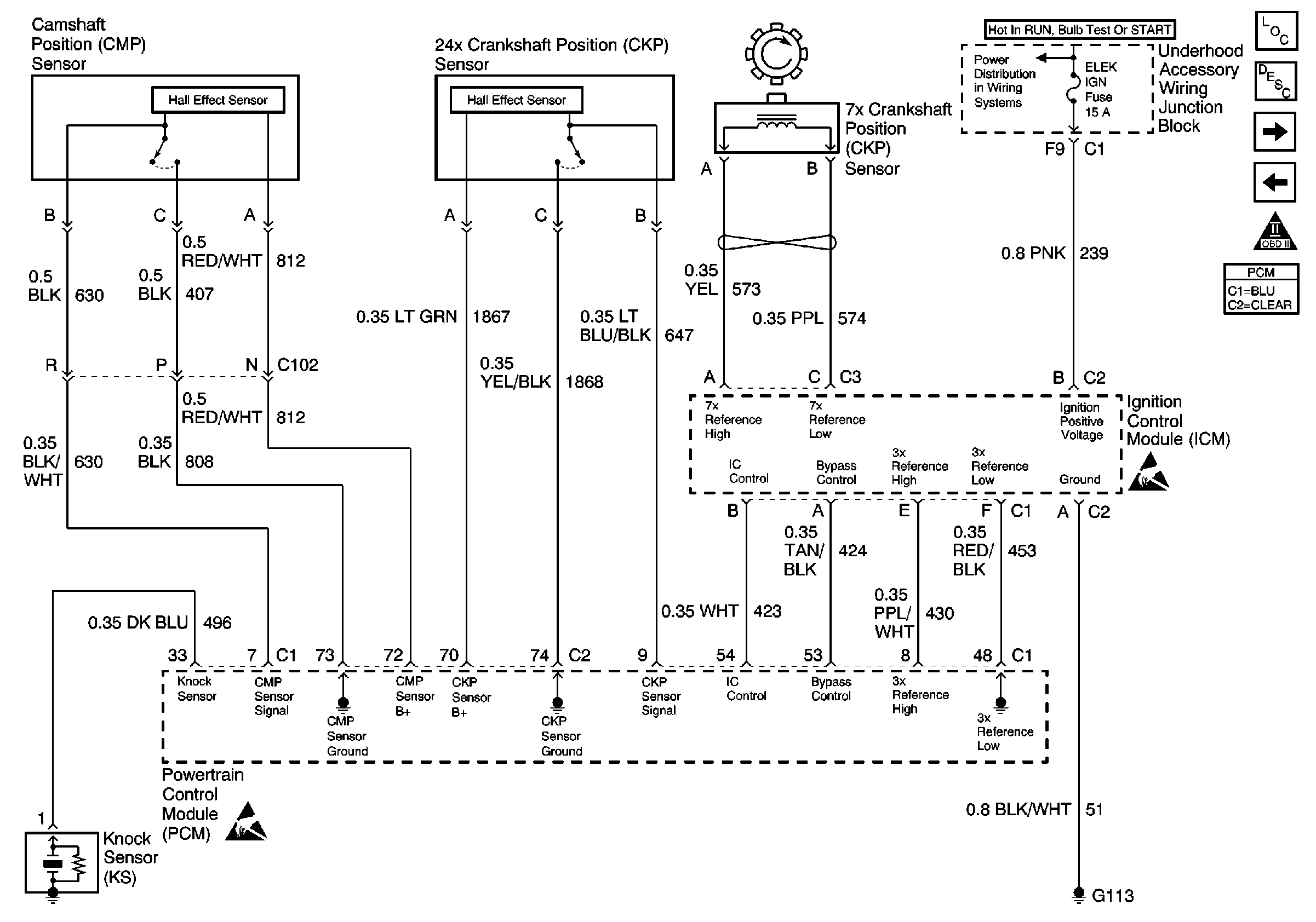
Refer to Engine Controls Schematic
CKP, CMP, ICM and Knock Sensor

.
Circuit Description
When the ignition switch is first turned ON, the PCM energizes the fuel pump relay which applies power to the in-tank fuel pump. The fuel pump relay will remain on as long as the engine is running or cranking and the PCM is receiving 3X reference pulses. If no 3X reference pulses are present, the PCM de-energizes the fuel pump relay within 2 seconds after the ignition is turned ON, or the engine is stopped.
During cranking, the ignition control module monitors the crankshaft position sensor input for recognition of the sync signal. The sync signal is used to determine the correct cylinder pair to spark first. After the sync signal has been processed by the ignition control module, it sends a 3X reference signal to the PCM. When the PCM receives this signal it will command all six injectors to open for one priming shot of fuel in all cylinders. After the priming, the injectors are left OFF for the next six 3X reference signals from the ignition control module, two crankshaft revolutions. This allows each cylinder to use the fuel from the priming shot. During this waiting period, a cam signal will have been received by the PCM. After the true camshaft position is detected, the PCM operates the injectors sequentially. However, if the cam signal is not present at start-up, DTC P0341 Camshaft Position (CMP) Sensor Performance will set and the PCM will start sequential fuel delivery in random pattern with a 1 in 6 chance that fuel delivery is correct.
The sync signal is used only by the ignition control module. It is used for spark synchronization at start-up only (not passed to the PCM).
Diagnostic Aids
Inspect for the following items:
| • | Mass Air Flow is compared to a calculated Mass Air Flow based upon the MAP, TP, and engine RPM readings (speed density). A skewed/unresponsive MAP sensor at key ON will cause the predicted air flow value to be inaccurate. Compare MAP and TP sensor value to that of a known good vehicle. |
| • | Faulty engine coolant temperature (ECT) sensor. Using a scan tool, compare Engine Coolant Temperature with intake air temperature (IAT) on a completely cool engine. engine coolant temperature should be within 10°C of intake air temperature. If not, replace the ECT sensor. Refer to Engine Coolant Temperature Sensor Replacement . |
Many situations may lead to an intermittent condition. Perform each inspection or test as directed.
Important: : Remove any debris from the connector surfaces before servicing a component. Inspect the connector gaskets when diagnosing or replacing a component. Ensure that the gaskets are installed correctly. The gaskets prevent contaminate intrusion.
| • | Loose terminal connection |
| - | Use a corresponding mating terminal to test for proper tension. Refer to Testing for Intermittent Conditions and Poor Connections , and to Connector Repairs in Wiring Systems for diagnosis and repair. |
| - | Inspect the harness connectors for backed out terminals, improper mating, broken locks, improperly formed or damaged terminals, and faulty terminal to wire connection. Refer to Testing for Intermittent Conditions and Poor Connections , and to Connector Repairs in Wiring Systems for diagnosis and repair. |
| • | Damaged harness--Inspect the wiring harness for damage. If the harness inspection does not reveal a problem, observe the display on the scan tool while moving connectors and wiring harnesses related to the sensor. A change in the scan tool display may indicate the location of the fault. Refer to Wiring Repairs in Wiring Systems for diagnosis and repair. |
| • | Inspect the powertrain control module (PCM) and the engine grounds for clean and secure connections. Refer to Wiring Repairs in Wiring Systems for diagnosis and repair. |
If the condition is determined to be intermittent, reviewing the Snapshot or Freeze Frame/Failure Records may be useful in determining when the DTC or condition was identified.
Test Description
The numbers below refer to the step numbers on the diagnostic table:
-
Testing for spark at an ignition wire will determine if the problem is with the 7X crankshaft position sensor input to the IC module. By using J 26792 spark tester to test for spark at the ignition coil towers, each ignition coils ability to produce at least 25,000 volts is verified.
-
A blinking J 34730-380 injector load tester LEDs verifies that the PCM is capable of activating the injectors.
A non-blinking J 34730-380 injector load tester LEDs indicates a possible fault condition in the fuel injector circuits.
Step | Action | Values | Yes | No | ||||||||||||||||||||||||||
|---|---|---|---|---|---|---|---|---|---|---|---|---|---|---|---|---|---|---|---|---|---|---|---|---|---|---|---|---|---|---|
1 | Did you perform the Powertrain On Board Diagnostic (OBD) System Check? | -- | ||||||||||||||||||||||||||||
2 |
Important: : If P0101, P0123, P0201-P0206, P0230, P0601-P0602, P1374, P1626, P1629 DTCs are stored diagnose those DTCs first.
Does the Fuel Pump run while being commanded on? | -- | ||||||||||||||||||||||||||||
3 |
Is the fuel pressure within the specified value? | 358-405 kPa (52-59 psi) | ||||||||||||||||||||||||||||
4 |
Does the scan tool indicate 3X reference signal present? | -- | ||||||||||||||||||||||||||||
Is there spark present? | -- | |||||||||||||||||||||||||||||
Does all of the LEDs for cylinders 1-6 flash? | -- | Go to Fuel Injector Solenoid Coil Test - Engine Coolant Temperature Between 10-35 Degrees C (50-95 Degrees F) or Fuel Injector Solenoid Coil Test - Engine Coolant Temperature Outside 10-35 Degrees C (50-95 Degrees F) | ||||||||||||||||||||||||||||
7 | Inspect the engine for the following conditions:
Did you find and correct the condition? | -- |
