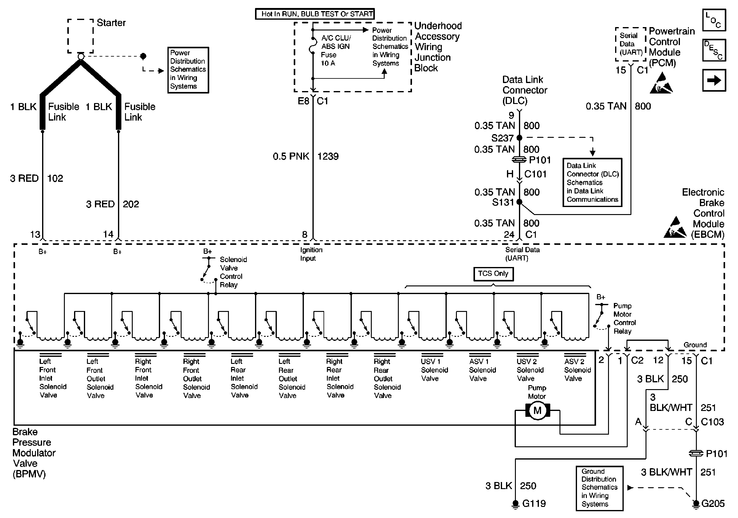
Circuit Description
The EBTCM is required to operate within a specified range of voltage to function properly. During ABS and TCS operation, there are current requirements that will cause the voltage to drop. Because of this, voltage is monitored out of ABS/TCS control to indicate a good charging system condition, and also during ABS/TCS control when voltage may drop significantly. The EBTCM also monitors for high voltage conditions which could damage the EBTCM.
Conditions for Setting the DTC
| • | The EBTCM operating voltage at terminal 8 falls below 9.4 volts out of ABS/TCS control, or 8.8 volts during ABS/TCS control. |
| • | The EBTCM operating voltage at terminal 8 rises above 17.4 volts. |
| • | The low voltage or the high voltage is detected for more than 500 milliseconds with the vehicle speed above 6 km/h (3.6 mph). |
Action Taken When the DTC Sets
| • | A malfunction DTC is stored. |
| • | The ABS/TCS indicator lamps are turned on. |
| • | The ABS/TCS is disabled. |
Conditions for Clearing the DTC
| • | The condition for the DTC is no longer present, the scan tool Clear DTCs function is used. |
| • | 100 ignition cycles have passed with no DTC(s) detected. |
Diagnostic Aids
| • | It is very important that a thorough inspection of the wiring and connectors be performed. Failure to carefully and fully inspect wiring and connectors may result in misdiagnosis, causing part replacement with reappearance of the malfunction. |
| • | Thoroughly inspect any circuitry that may be causing the complaint for the following conditions: |
| - | Backed out terminals |
| - | Improper mating |
| - | Broken locks |
| - | Improperly formed or damaged terminals |
| - | Poor terminal-to-wiring connections |
| - | Physical damage to the wiring harness |
| • | The following conditions may cause an intermittent malfunction: |
| - | A poor connection |
| - | Rubbed-through wire insulation |
| - | A broken wire inside the insulation |
| • | If an intermittent malfunction exists refer to General Electrical Diagnosis in Wiring Systems for further diagnosis. |
Test Description
The number(s) below refer to the step number(s) on the diagnostic table.
-
This step checks if the voltage is above the maximum of the range.
-
This step checks if the voltage is below the minimum of the range.
-
This step checks for the integrity of the ground circuit.
Step | Action | Value(s) | Yes | No |
|---|---|---|---|---|
SCHEMATIC REFERENCE: ABS Schematics
| ||||
1 | Was a Diagnostic System Check performed? | -- | ||
Is the monitored battery voltage within the specified range? | 0-17.4 V | |||
3 | Use a J 39200 DMM to measure the voltage between the battery positive terminal and ground. Is the voltage within the specified range? | 0-17.4 V | Go to Charging System Test in Engine Electrical | |
Continue to monitor the battery voltage with the scan tool while running the engine at approximately 2000 RPM. Is the monitored battery voltage within the specified range? | 0-9.4 V | |||
5 |
Did DTC C0896 reset? | -- | ||
Is the resistance within the specified range? | 0-5ohms | |||
7 | Repair open or high resistance in CKT 251. Refer to Wiring Repairs in Wiring Systems. Is the repair complete? | -- | -- | |
8 |
Is the voltage within the specified range? | Above 9.4 Volts | ||
9 |
Is the resistance within the specified range? | 0-5ohms | Go to Charging System Test in Engine Electrical | |
10 | Repair high resistance in CKT 1239. Refer to Wiring Repairs in Wiring Systems. Is the repair complete? | -- | ||
11 |
Did DTC C0896 reset? | -- | ||
12 | Replace the EBTCM. Refer to Electronic Brake and Traction Control Module Replacement . Is the repair complete? | -- | -- | |

