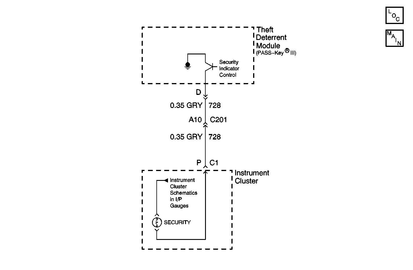
Circuit Description
The SECURITY indicator lamp notifies the driver of the theft deterrent system status. The theft deterrent module controls the operation of the SECURITY indicator lamp. The SECURITY indicator lamp is part of the instrument panel cluster. The instrument panel cluster provides positive voltage to the SECURITY indicator lamp bulb when the ignition switch is in the RUN, Bulb Test, or CRANK position. A control circuit is wired between the instrument panel cluster and the theft deterrent module. This control circuit allows the theft deterrent module to provide a path to ground to the SECURITY indicator lamp bulb. This causes the SECURITY indicator lamp bulb to remain off, turn on, or flash, based on the system status. Refer to system operation for indicator statues.
Conditions for Running the DTC
The ignition switch must be in the RUN, Bulb Test or START position.
Conditions for Setting the DTC
The theft deterrent module detects a short to voltage in the SECURITY indicator lamp control circuit for 1 second.
Action Taken When the DTC Sets
DTC B0688 sets as current DTC in the theft deterrent module.
Conditions for Clearing the MIL/DTC
| • | The theft deterrent module no longer detects a short to voltage condition in the SECURITY indicator lamp control circuit during the ignition cycle. |
| • | A history DTC will clear after 100 consecutive fault-free ignition cycles. An ignition cycle consists of an ignition switch transition from LOCK/OFF to RUN. |
| • | Using a scan tool |
Diagnostic Aids
A poor connection or intermittent connection may cause this DTC to set. Refer to Testing for Intermittent Conditions and Poor Connections in Wiring Systems.
Test Description
-
This step determines whether the condition that causes this DTC to set is currently present or is intermittent.
-
This step checks for an intermittent short to B+ in the SECURITY indicator control circuit.
-
This step checks for a short to B+ in the SECURITY indicator lamp control circuit.
-
This step checks for a short to B+ within the instrument panel cluster. This step also checks for a faulty indicator bulb.
Step | Action | Yes | No | |
|---|---|---|---|---|
1 | Did you perform the Theft Deterrent Diagnostic System Check? | Go to Step 2 | ||
While observing the SECURITY indicator, turn the ignition switch from LOCK/OFF to RUN. Did the SECURITY indicator turn on for at least 2 seconds? | Go to Step 3 | Go to Step 4 | ||
Did this DTC reset as a current DTC? | Go to Step 4 | Go to Diagnostic Aids | ||
Test the control circuit of the SECURITY indicator lamp for a short to B+. Refer to Circuit Testing and Wiring Repairs in Wiring Systems. Did you find and correct the condition? | Go to Step 7 | Go to Step 5 | ||
Inspect for a short to B+, or a faulty indicator bulb in the instrument panel cluster. Did you find and correct the condition? | Go to Step 7 | Go to Step 6 | ||
6 |
Did you complete the repair? | Go to Step 7 | -- | |
7 |
Does the DTC reset? | Go to Step 2 | System OK | |
