Cold Engine Tick Noise (Replace Pistons)

| Subject: | Cold Engine Tick Noise (Replace Pistons) |
| Models: | 2000-01 Buick Century |
| 2000-01 Chevrolet Lumina, Malibu |
| 2000-01 Pontiac Grand Prix |
| with 3.1L Engine (VIN J -- RPO LG8 |
Condition
Some customers may comment on a ticking noise (similar, but not related to valve or lifter noise) that occurs 10-15 seconds after a cold engine start. The noise will last for 1 to 2 minutes, and will fade as the engine reaches operating temperature.
Cause
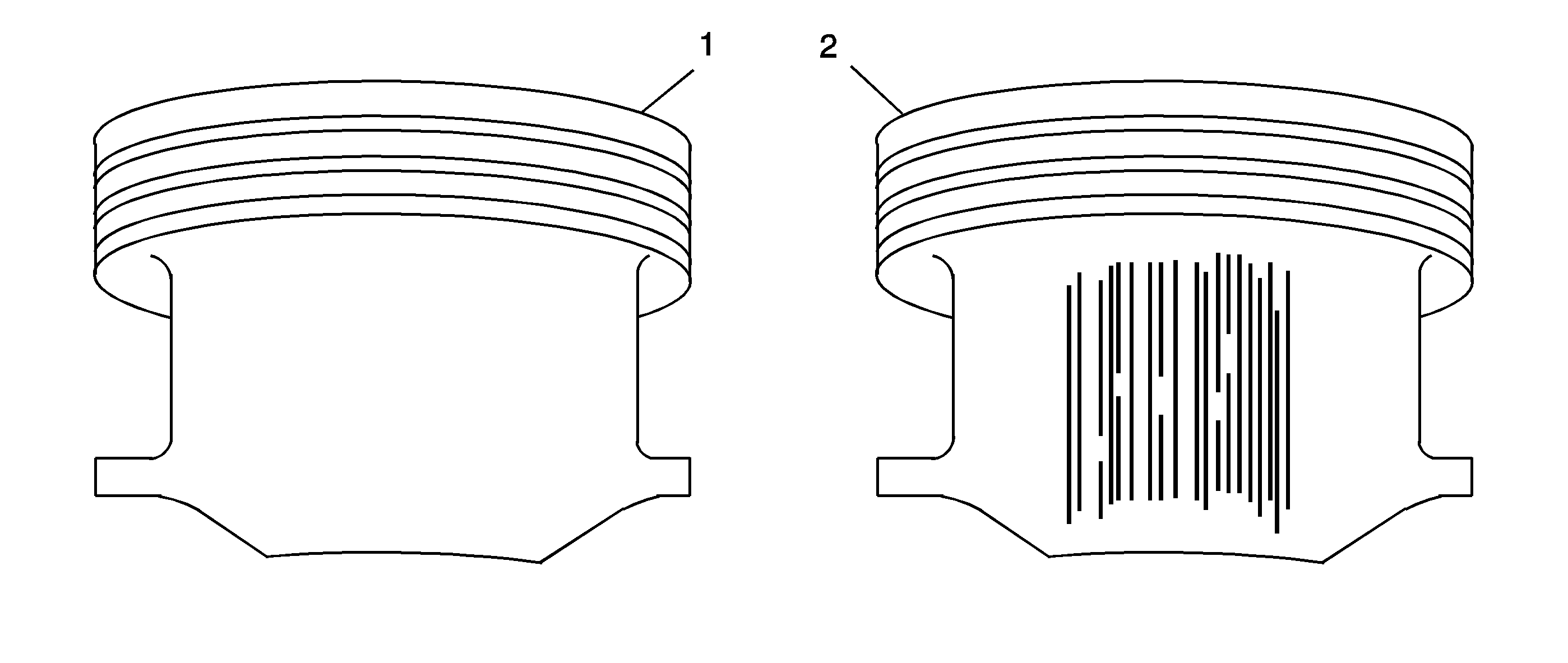
The noise may be caused by excessive piston to bore clearance during cold engine operation resulting from the specific piston design used in cylinders 1 through 4.
Correction
Service pistons for cylinders 1 through 4 will now be of the same design of those used for all production 2000 and 2001 for cylinders 5 and 6, and will have polymer coated piston skirts. Pistons in cylinders 5 and 6 are not exhibiting the described noise condition.
Important:
• Note that this is a customer annoyance issue, and does not affect
the durability or life of the engine. • Removal of pistons from engine cylinders 5 and 6 is NOT necessary
if equipped with polymer coated pistons. It is recommended to rotate the crankshaft
until the piston skirt is exposed in the lower crankcase area for inspection.
Replace pistons in engine cylinder positions 5 and 6 ONLY if there is evidence
of damage to the polymer coating on the piston skirt, or scoring on the cylinder
wall (heavy scratches) is evident. Detailed diagnosis of cylinder wall/piston
skirt wear is discussed in step 4 below.
Repair Procedure
Tools Required
| • | J 24086 Connecting Rod Press |
| • | J 24086-C Piston Pin Remover/Installer |
| • | Connecting Rod Oven (Rod Kiln) |
Piston and Connecting Rod Disassemble
- Follow the base engine noise diagnostic information found in the Engine Repair Section of the Service Manual.
- Prior to piston/connecting rod removal, mark or identify the piston/connecting rod assembly, and its orientation to the front of the engine, before removal.
- Remove the pistons from engine cylinders 1-4 following instructions found in the Engine Repair Section of the Service Manual.
Non-Polymer Coated Piston
Piston and Connecting Rod Assemble
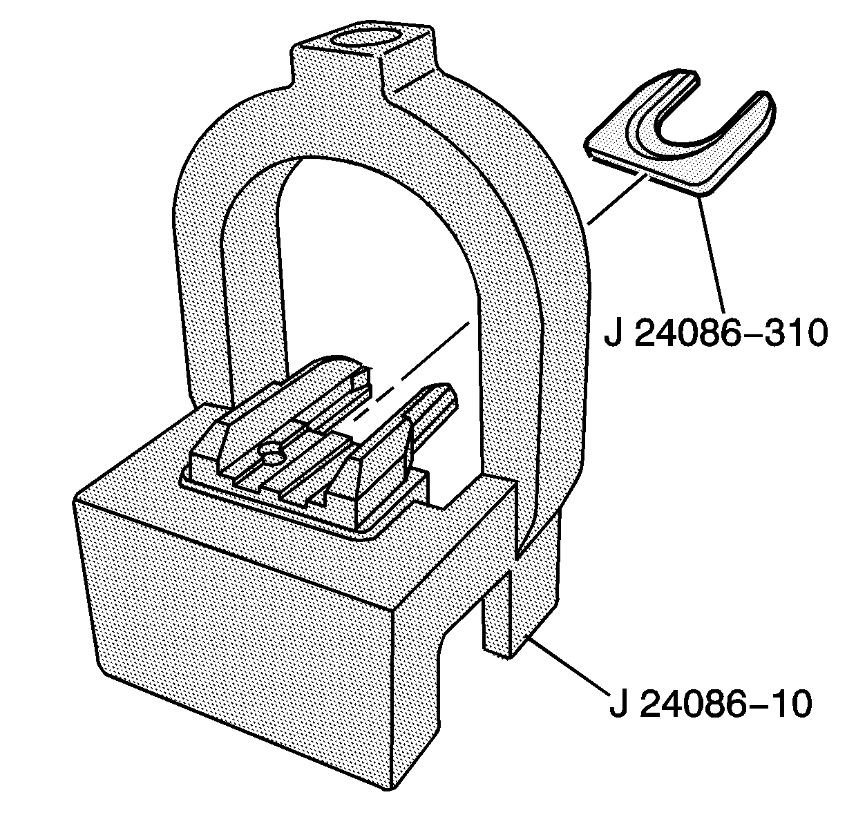
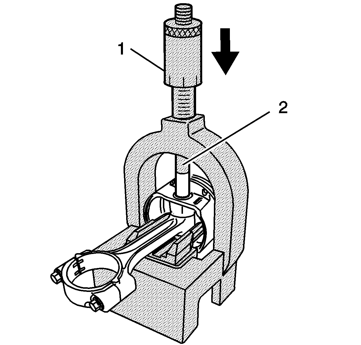
- Install the J 24086-310 fork insert into the J 24086-10 fixture support assembly.
- Adjust the J 24086-9 installation pin to the following setting:
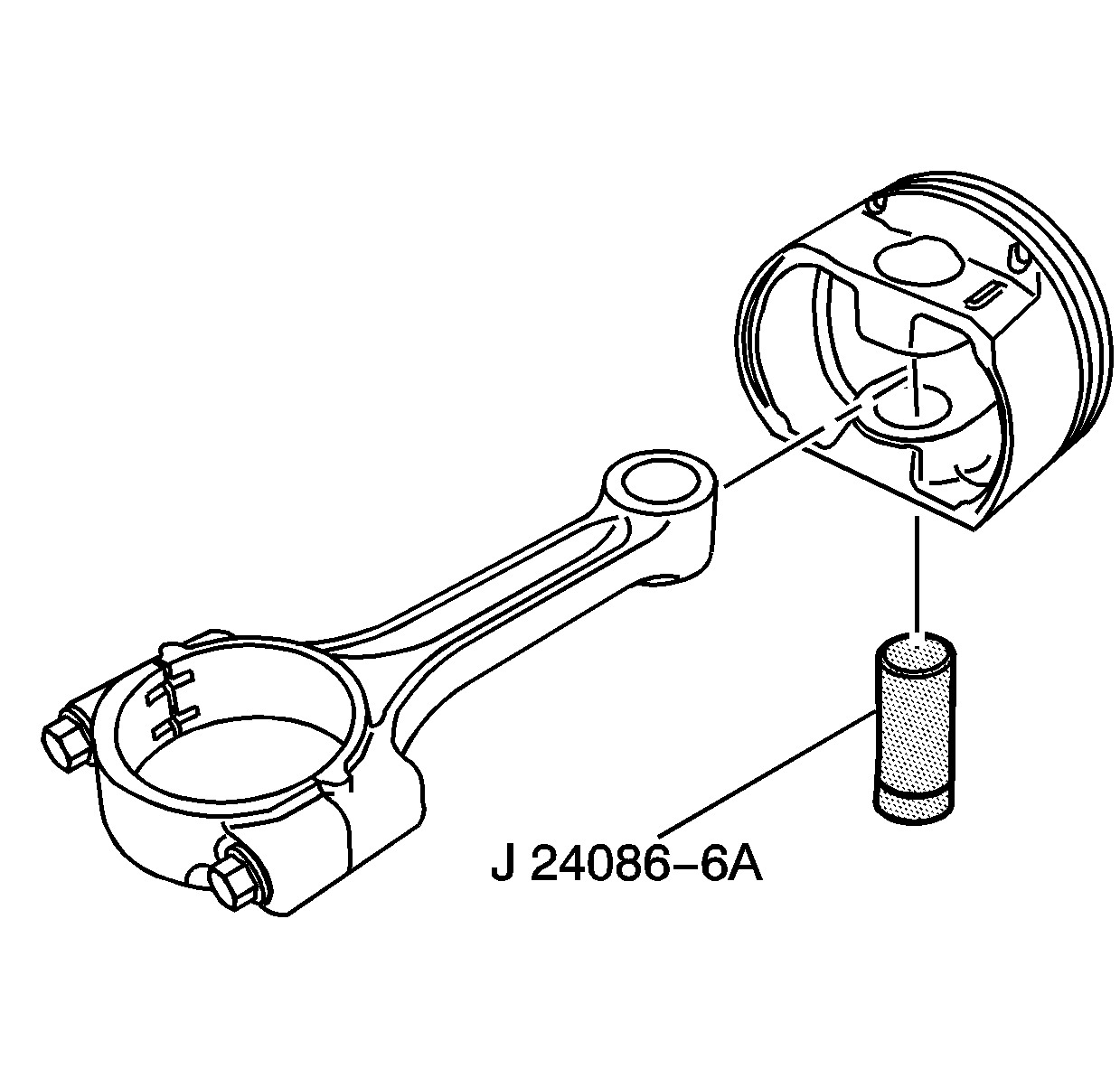
- Using a connecting rod kiln, heat the piston pin end of the connecting rod to 320°C (612°F).
- Refer to the above illustration. Assemble the piston, the connecting rod, and the J 24086-6A adapter as shown. Insert the piston and connecting rod assembly into the J 24086-10 fixture support assembly.
- Refer to the above illustration. Install the J 24086-105 (2) onto the piston pin. Position the J 24086-9 (1) though the J 24086-10 fixture support assembly and onto the J 24086-105 (2).
- Press the J 24086-9 (1) installation pin until it bottoms on the J 24086-10 fixture support assembly.
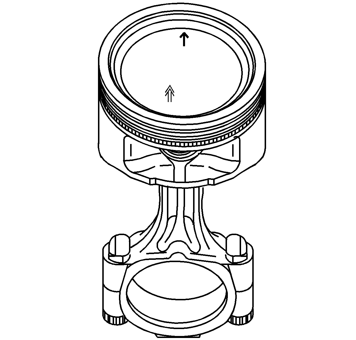
- Reinstall the piston rings onto the new piston. Refer to the Engine Repair Section of the Service Manual for proper ring gap positioning.
- Refer to the above illustration. Install the assembled piston and rod assembly into the engine. Verify that the directional arrows on the top of the piston point to the front of the engine.
- Follow the remaining engine assembly instructions found in the Engine Mechanical Section of the Service Manual.
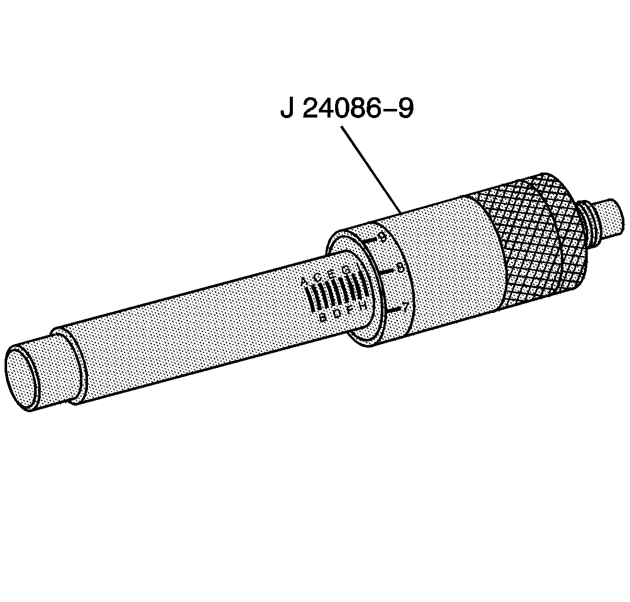
3.1 liter engine: G-7.
Caution: Avoid contact with HOT components. Wear safety glasses and protective heat gloves to avoid personal injury!
Notice: Applying excessive heat to the connecting rod may damage or distort the connecting rod or piston. Connecting rod temperatures should not exceed 320°C (612°F).
Notice: After the J 24086-9 installation pin bottoms on the J 24086-10 fixture support assembly, do not exceed a pressure of 35,000 kPa (5,000 psi), or damage to the connecting rod press may result.
Parts Information
Part Number | Description | Qty |
|---|---|---|
12564009 | LG8 3.1 Piston Assembly | 4 |
Parts are currently available from GMSPO.
Warranty Information
For vehicles repaired under warranty, use:
Labor Operation | Description | Labor Time |
|---|---|---|
J1307 | Piston Replace (Both Banks) | Use Published Labor Time |
