GM Service Manual Online
For 1990-2009 cars only
Figure 1:

Power, Ground, Brake Pressure Modulator Valves
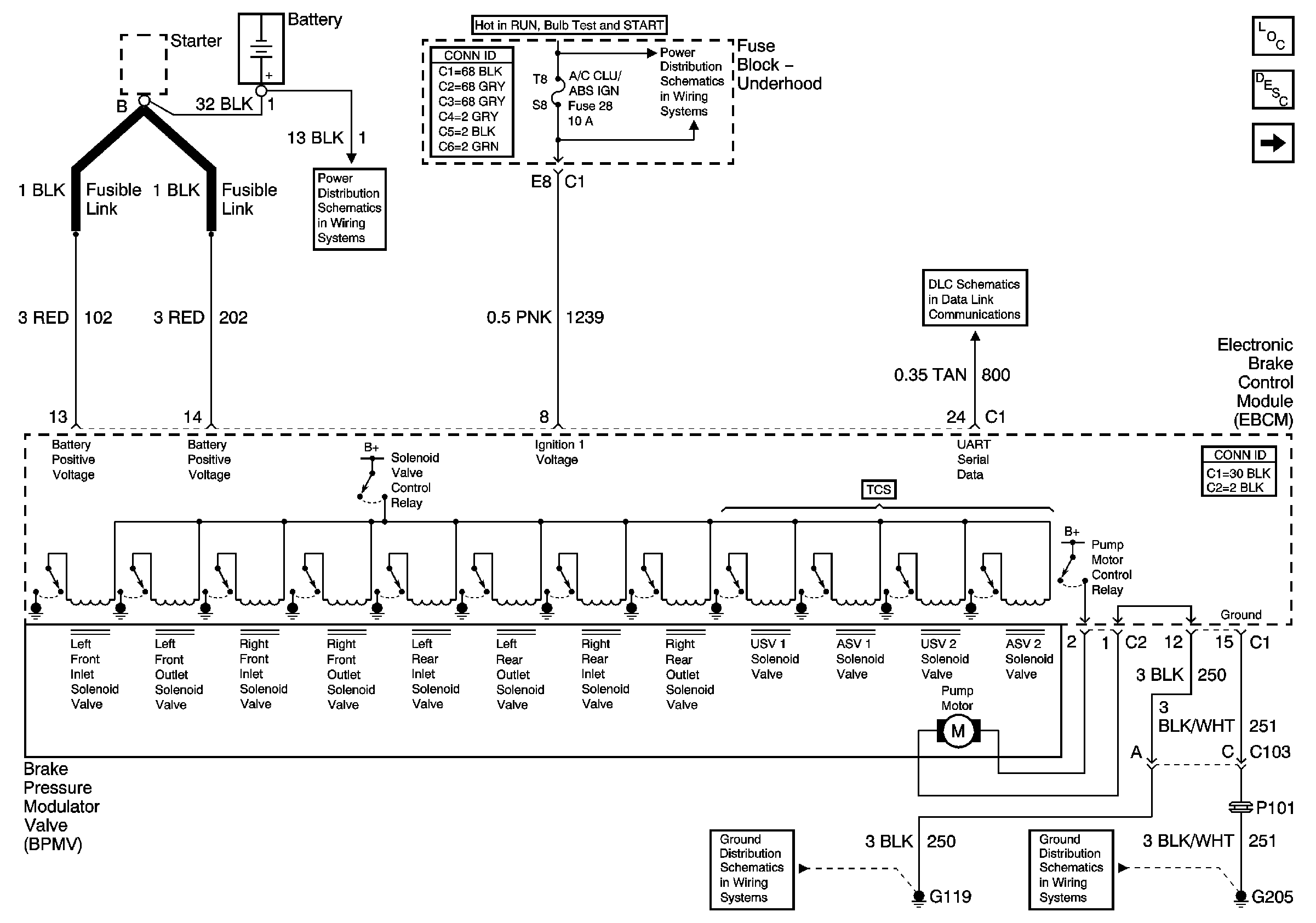

Object Number: 876178  Size: FS
Master Electrical Component List
ABS Description and Operation
ABS Indicator, Torque Signals, and Steering
BATT MAIN 1, 2 IGN MAIN 1, 2 HEADLAMPS, PARK LP, HVAC/RKE BATT, AIR, ECM SENSE, ALT SENSE, B/U LAMP, COOL FAN 1, 2 FUEL PUMP, FOG LP, HORN, INJ, IGN1-UH, ELEK IGN, TCC, A/C CLU/ABS IGN Fuses
TCC, ELEK IGN, and A/C CLU/ABS IGN Fuses
DLC
G119
G205
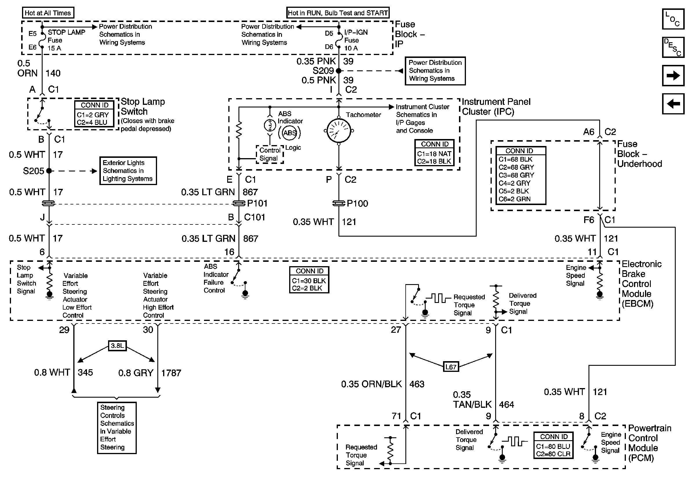
Figure 2:

ABS Indicator, Torque Signals, and Steering


Object Number: 876184  Size: FS
Master Electrical Component List
ABS Description and Operation
Traction Control
Power, Ground, and Brake Pressure Modulator Valves
BATT MAIN 1, ONSTAR, STOPLAMP, INT LAMP, and CIG LTR Fuses
IP-IGN, CRUISE, and ECM Fuses
Gages
Rear Turn Signals and Stop Lamps
Steering Controls
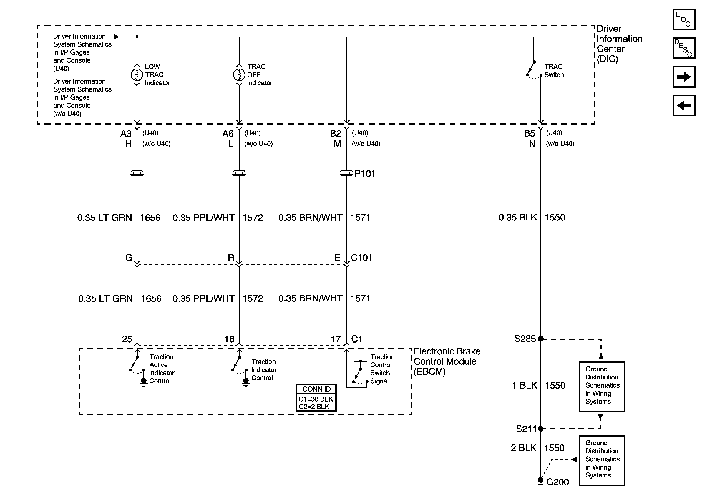
Figure 3:

Traction Control


Object Number: 876190  Size: FS
Master Electrical Component List
ABS Description and Operation
Wheel Speed Sensors
ABS Indicator, Torque Signals, and Steering
Driver Information Center (DIC)(w/U40)
Driver Information Center (DIC) (w/o U40)
G200, S211, S285
G200, G213, S375
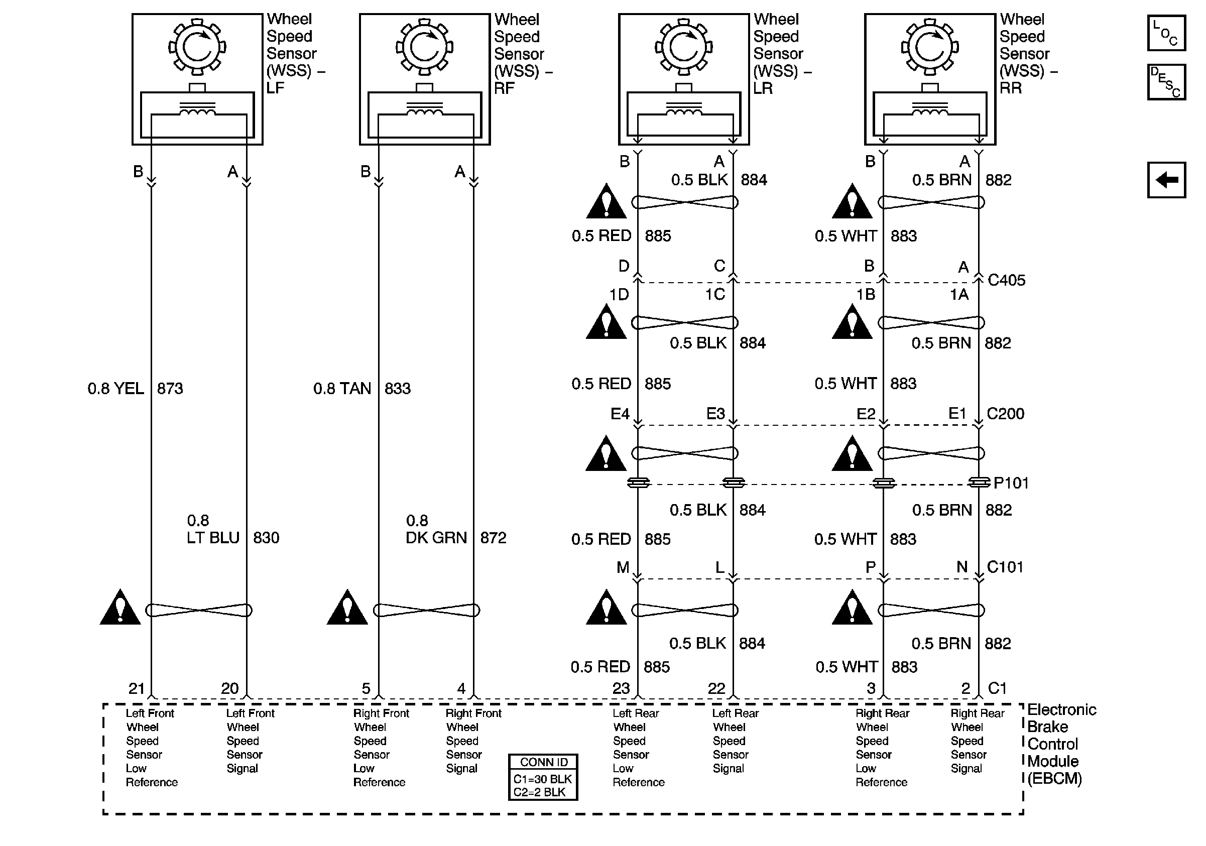
Figure 4:

Wheel Speed Sensors


Object Number: 794890  Size: FS
Master Electrical Component List
ABS Description and Operation
Traction Control
Antilock Brake System Schematic Icons