GM Service Manual Online
For 1990-2009 cars only
Makes
🢒
Pontiac
🢒
2005
🢒
Grand Prix
🢒
Vehicle Control Systems
🢒
Vehicle DTC Information
🢒 Antilock Brake System Schematics
Figure
1:
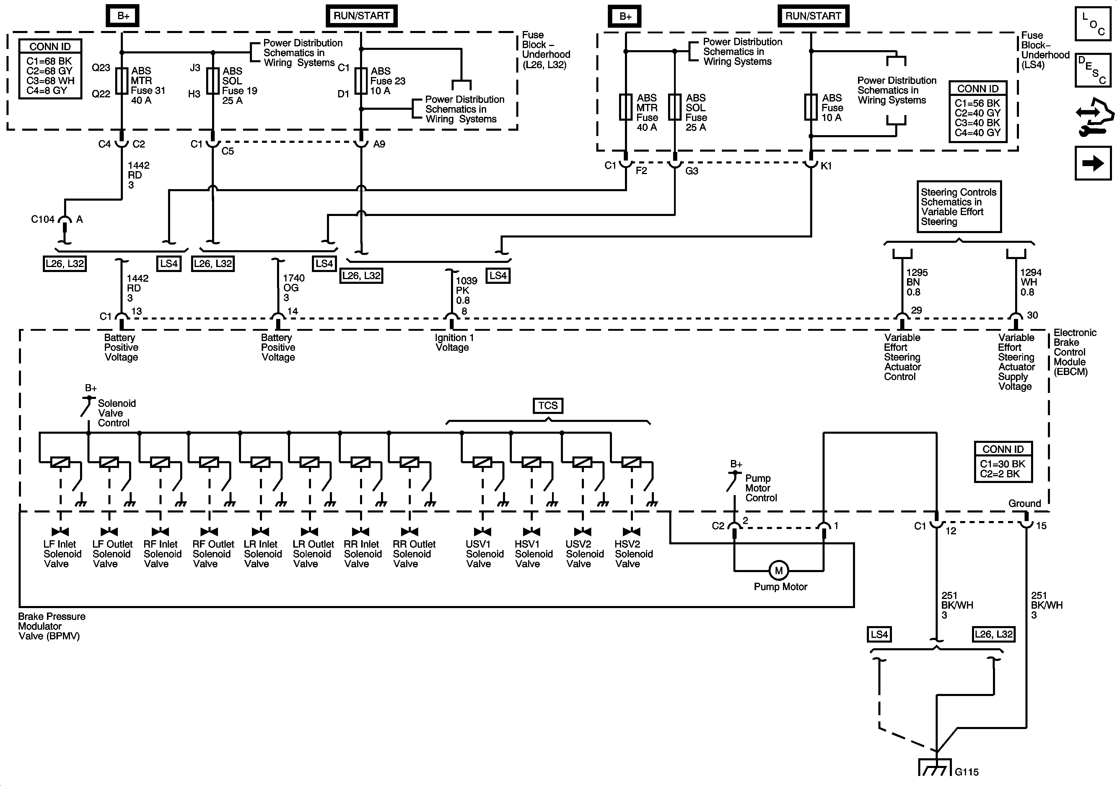
Power, Ground and Brake Pressure Modulator Valves
Master Electrical Component List
ABS Description and Operation
Control Module References
Indicator, ABS, Stability, and Traction Controls
Fuse Block Underhood Bussing
BATT MAIN 3, BATT MAIN 4, ABS MTR, ABS SOL, PCM/ETC, AIR PUMP, WASHER RVC, and AUX PWR Fuses
Fuse Block Underhood Bussing
ABS, TRANS SOL, PCM, SIR, DISPLAY, CRUISE SW Fuses, and CRANK Relay
Fuse Block - Underhood Bussing
BATT 3, BATT 4, ABS MTR, ABS SOL, ECM/TCM, WSW/RVC, and AUX PWR Fuses
ABS, TRANS, ECM IGN, AIRBAG/DISPLAY, COMPASS, HVAC Fuses and STRTR Relay
Steering Controls Schematics
G102, G115 and G201
Figure
2:
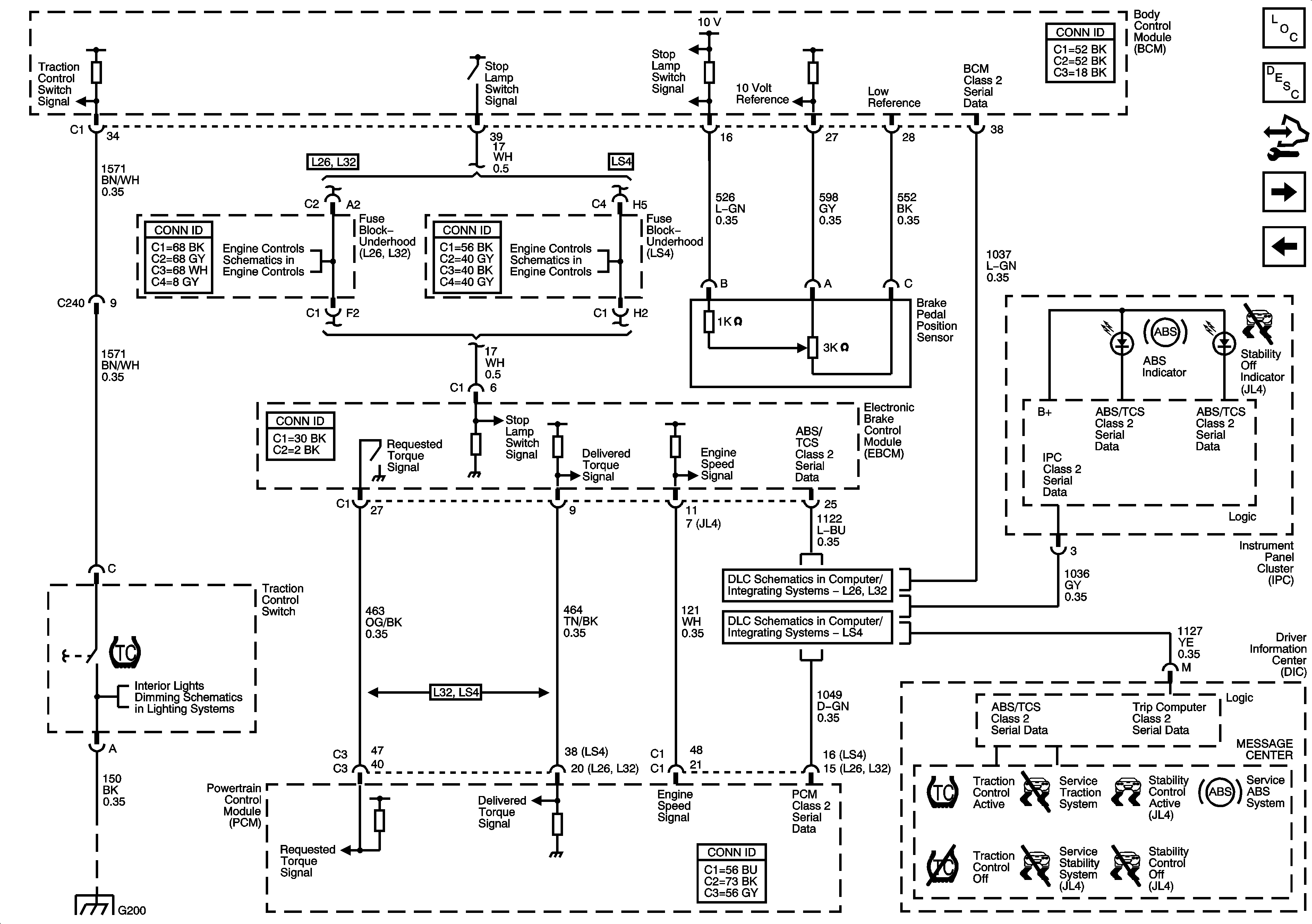
Indicators, ABS, Stability and Traction Controls
Master Electrical Component List
ABS Description and Operation
Control Module References
Stability Control Sensors (JL4)
Power, Ground and Brake Pressure Modulator Valves
Electronic Throttle Controls
Interior Lamp Switch, I/P and Driver Door Lighting
Data Link Communication
MAF/IAT Sensor, Stop Lamp Switch Signal and VSS
LS4
G200
Figure
3:
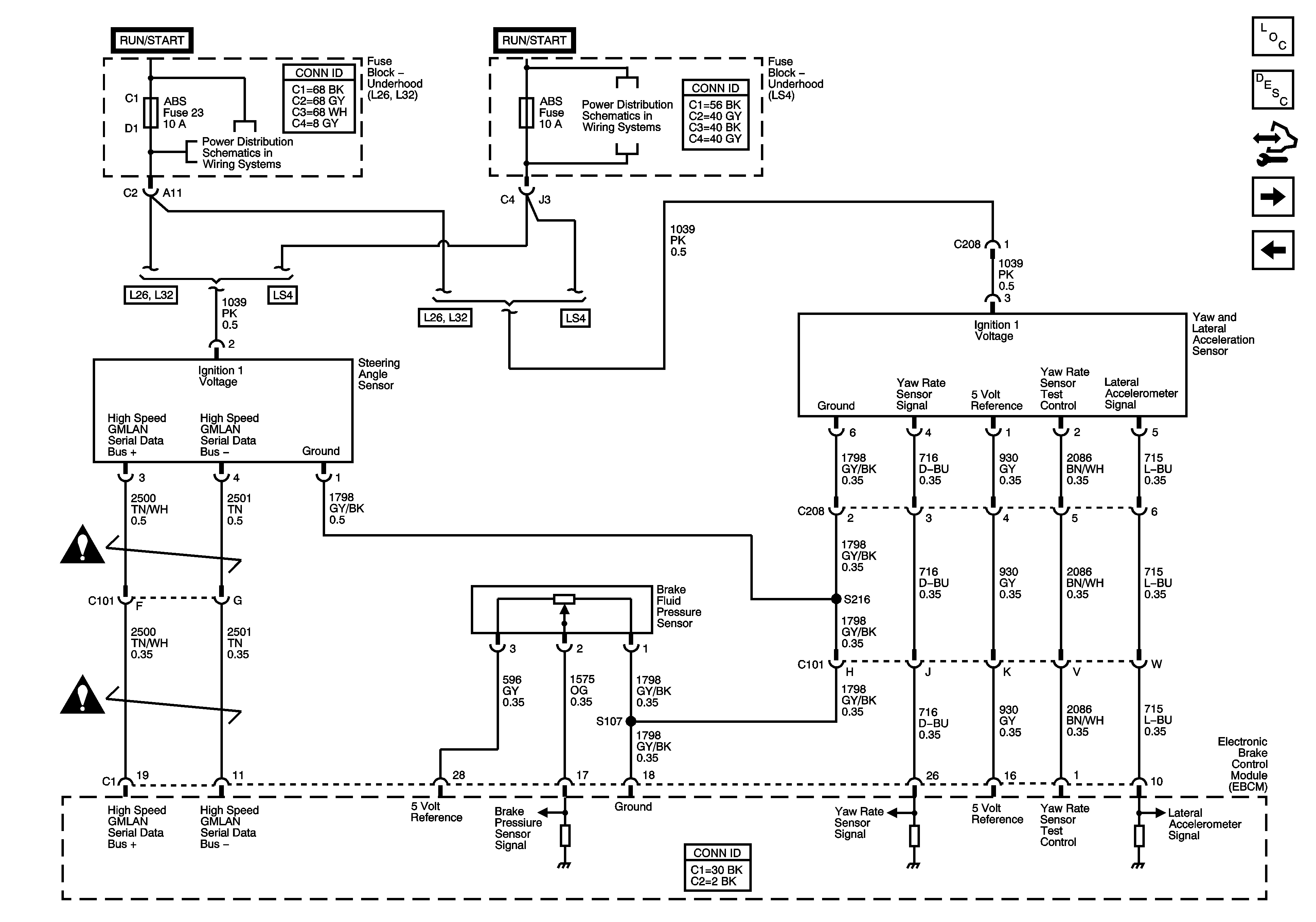
Stability Control Sensors - JL4
Master Electrical Component List
ABS Description and Operation
Control Module References
Wheel Speed Sensors
Indicator, ABS, Stability, and Traction Controls
Fuse Block Underhood Bussing
ABS, TRANS SOL, PCM, SIR, DISPLAY, CRUISE SW Fuses, and CRANK Relay
Fuse Block - Underhood Bussing
ABS, TRANS, ECM IGN, AIRBAG/DISPLAY, COMPASS, HVAC Fuses and STRTR Relay
Antilock Brake System Schematic Icons
Figure
4:
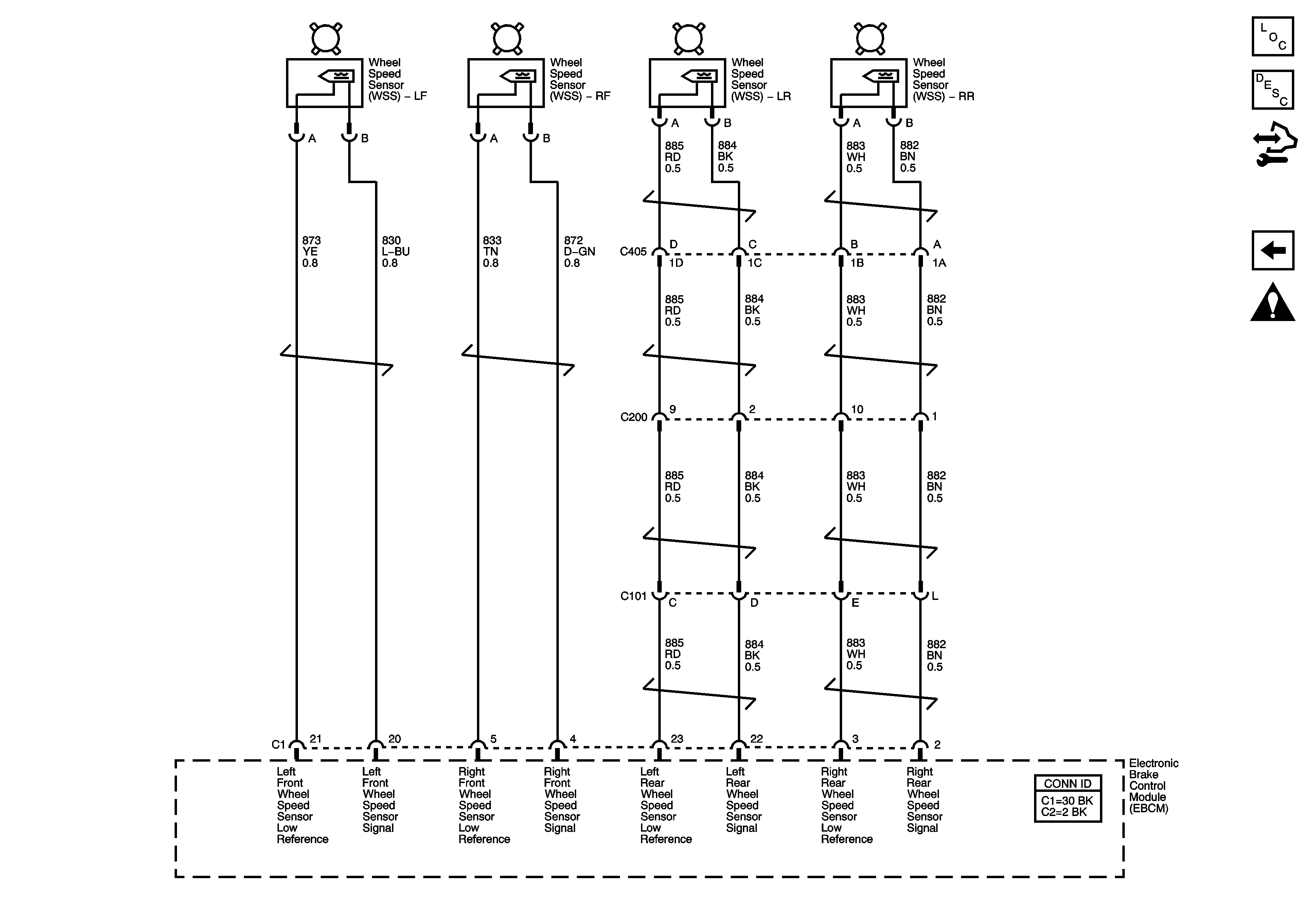
Wheel Speed Sensors
Master Electrical Component List
ABS Description and Operation
Control Module References
Stability Control Sensors (JL4)
Antilock Brake System Schematic Icons