Removal Procedure
- Disconnect the negative battery cable. Refer to
Battery Negative Cable Disconnection and Connection
.
- Remove the fuel injector sight shield. Refer to
Fuel Injector Sight Shield Replacement
.
- Remove the air cleaner intake duct. Refer to
Air Cleaner Inlet Duct Replacement
.
- Drain the cooling system. Refer to
Cooling System Draining and Filling
.
- Remove the right spark plug wires from the ignition control module and the upper intake manifold and reposition the wires. Refer to
Spark Plug Wire Replacement
.
- Relieve the fuel pressure. Refer to
Fuel Pressure Relief
.
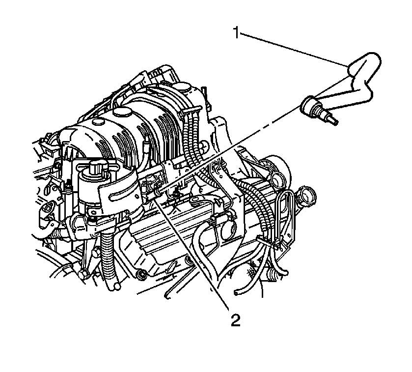
- Remove the brake booster hose (1) from the vacuum source manifold (2).
- Disconnect the electrical connectors from the following:
| • | Electronic throttle control (ETC) |
| • | Manifold absolute pressure (MAP) sensor |
| • | Mass air flow (MAF) sensor |
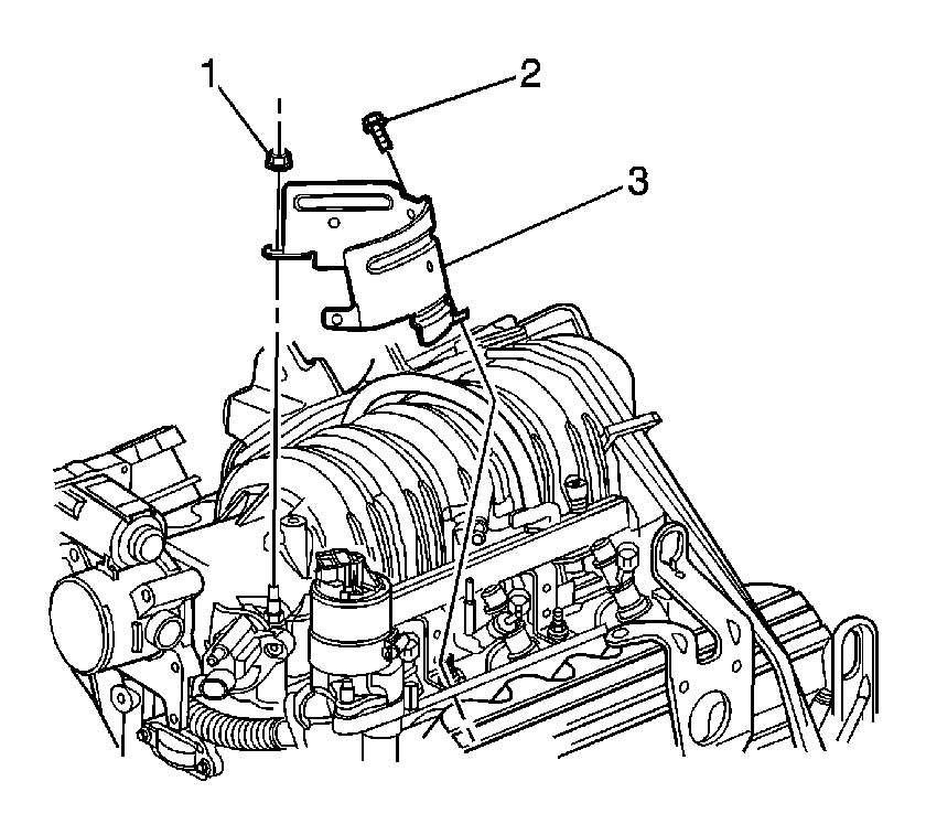
- Remove the exhaust gas recirculation (EGR) valve wiring harness heat shield nut (1), bolt (2) and the EGR heat
shield (3).
- Disconnect the EVAP purge solenoid pipe quick connect fitting. Refer to
Plastic Collar Quick Connect Fitting Service
.
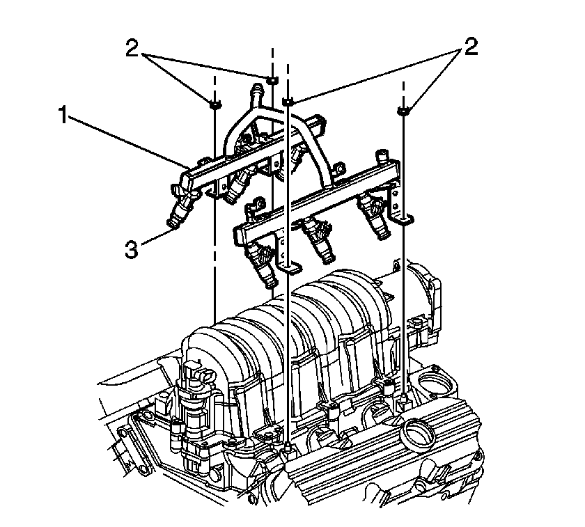
- Remove the fuel rail assembly nuts (2).
- Remove the fuel rail assembly (1) with the fuel injectors (3).
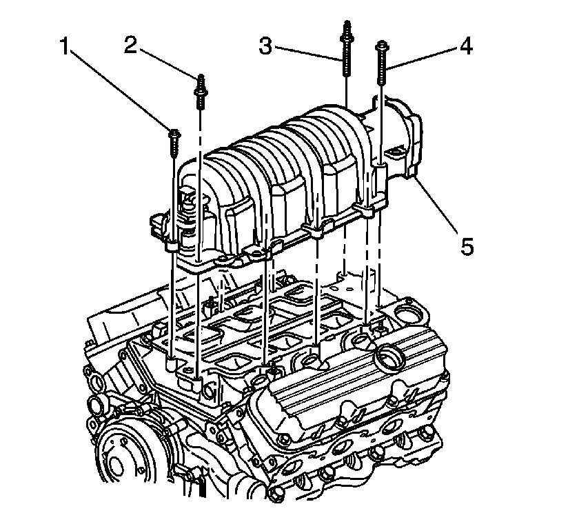
- Remove the upper intake manifold bolts (1, 4) and the studs (2, 3).
- Clean the upper intake manifold bolt threads.
- Remove the upper intake manifold.
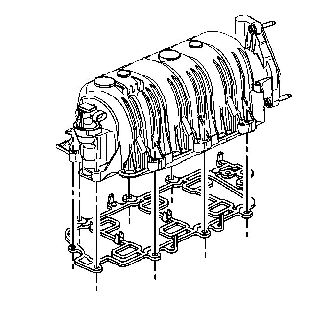
- Remove the upper-to-lower intake manifold carrier gasket
from the upper intake manifold.
- If the upper intake manifold is being replaced, remove the following:
| • | Manifold absolute pressure (MAP) sensor |
| • | Positive crankcase ventilation (PCV) valve |
Installation Procedure
- If the manifold was replaced install the following:
| • | Positive crankcase ventilation (PCV) valve |
| • | Manifold absolute pressure (MAP) sensor |

- Install the upper-to-lower intake manifold carrier gasket
to the upper intake manifold.

- Carefully install the upper intake manifold (5) onto the lower intake manifold. Ensure that the alignment pins in the upper
intake manifold align with the holes in the lower intake manifold.
- Apply thread lock compound to the threads of the bolts (1, 4) and the studs (2, 3). Refer to
Adhesives, Fluids, Lubricants, and Sealers
for the correct part number.
Notice: Refer to Fastener Notice in the Preface section.
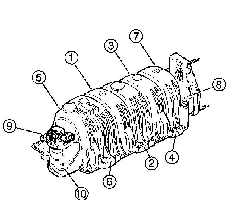
- Install the upper intake manifold bolts and the studs (1-10).
Tighten
Tighten the bolts in sequence to 10 N·m (89 lb in).

- Lightly coat the fuel injectors (3) with clean engine oil.
Important: Ensure the fuel rail is fully seated in the lower intake manifold assembly.
- Install the fuel rail assembly (1) to the lower intake assembly.
- Install the fuel rail nuts (2).
Tighten
Tighten the nuts to 10 N·m (89 lb in).
- Connect the EVAP purge solenoid pipe quick connect fitting. Refer to
Plastic Collar Quick Connect Fitting Service
.

- Install the EGR valve wiring harness heat shield (3), the nut (1) and the bolt (2).
Tighten
Tighten the nut and the bolt to 10 N·m (89 lb in).

- Install the brake booster hose (1) to the vacuum source manifold (2).
- Connect the electrical connectors to the following:
| • | Mass air flow (MAF) sensor |
| • | Manifold absolute pressure (MAP) sensor |
| • | Electronic throttle control (ETC) |
- Install the right spark plug wires to the ignition control module and the upper intake manifold. Refer to
Spark Plug Wire Replacement
.
- Install the air cleaner intake duct. Refer to
Air Cleaner Inlet Duct Replacement
.
- Install the fuel injector sight shield. Refer to
Fuel Injector Sight Shield Replacement
.
- Fill the cooling system. Refer to
Cooling System Draining and Filling
.
- Connect the negative battery cable. Refer to
Battery Negative Cable Disconnection and Connection
.
- Inspect for fluid or vacuum leaks.


