GM Service Manual Online
For 1990-2009 cars only
Figure 1:

ECM Power, Ground, MIL, and Serial Data


Object Number: 1653973  Size: FS
Master Electrical Component List
Engine Control Module Description
Control Module References
5-Volt and Low Reference Bussing
Engine Controls Schematic Icons
Ignition Switch
Ignition Switch
G112 (LS4), AND G113 (LS4)
Ignition Switch
ABS, TRANS, ECM IGN, AIRBAG/DISPLAY, COMPASS, HVAC Fuses and STRTR Relay
Fuse Block - Underhood Bussing
G112 (LS4), AND G113 (LS4)
BATT 3, BATT 4, ABS MTR, ABS SOL, ECM/TCM/WSW/RVC, and AUX PWR Fuses
LS4
Figure 2:

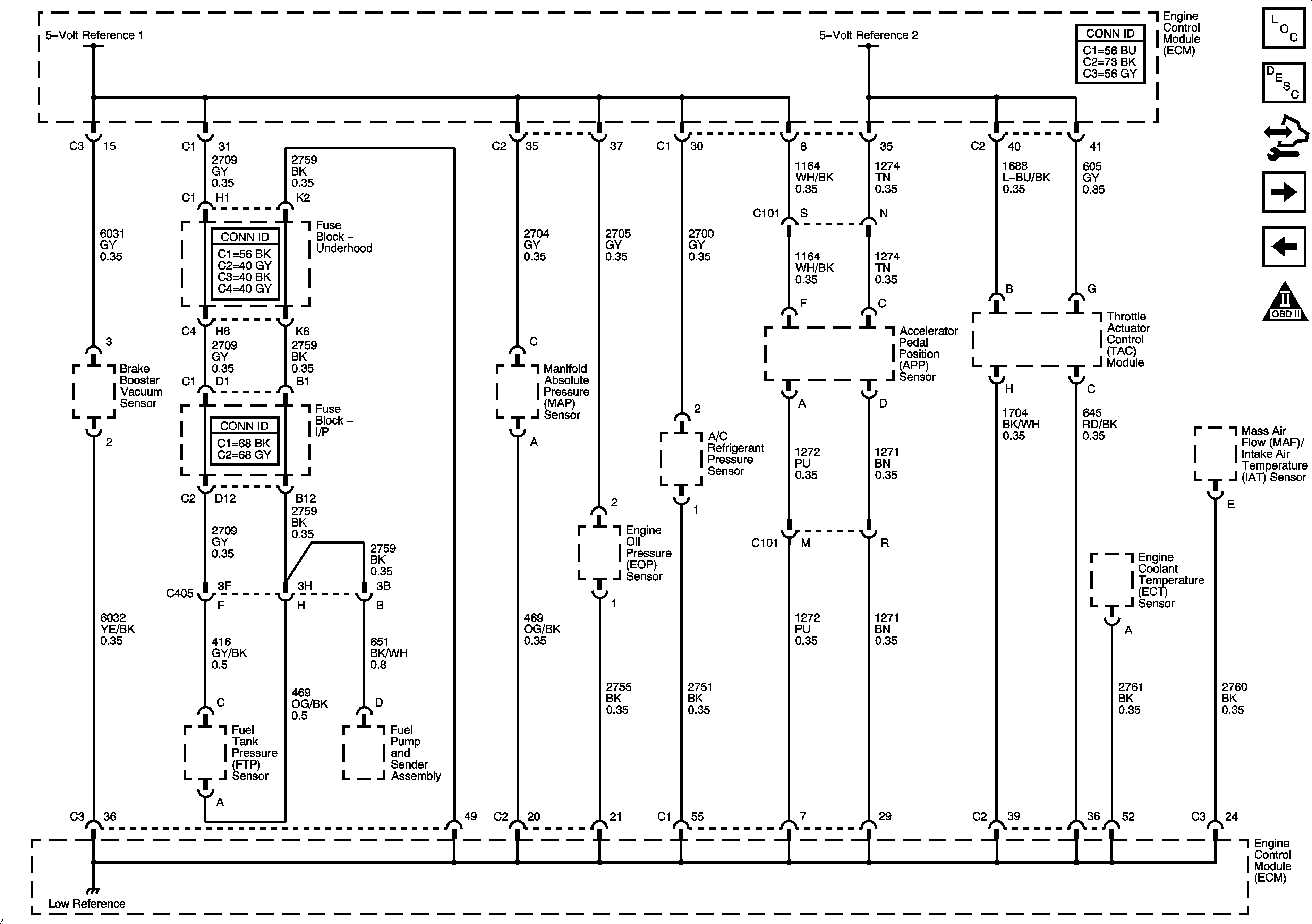
5-Volt and Low Reference Bussing


Object Number: 1653975  Size: FS
Master Electrical Component List
Engine Control Module Description
Control Module References
MAP, ECT, and MAF/IAT Sensors
ECM Power, Ground, MIL, and Serial Data
Engine Controls Schematic Icons
Figure 3:

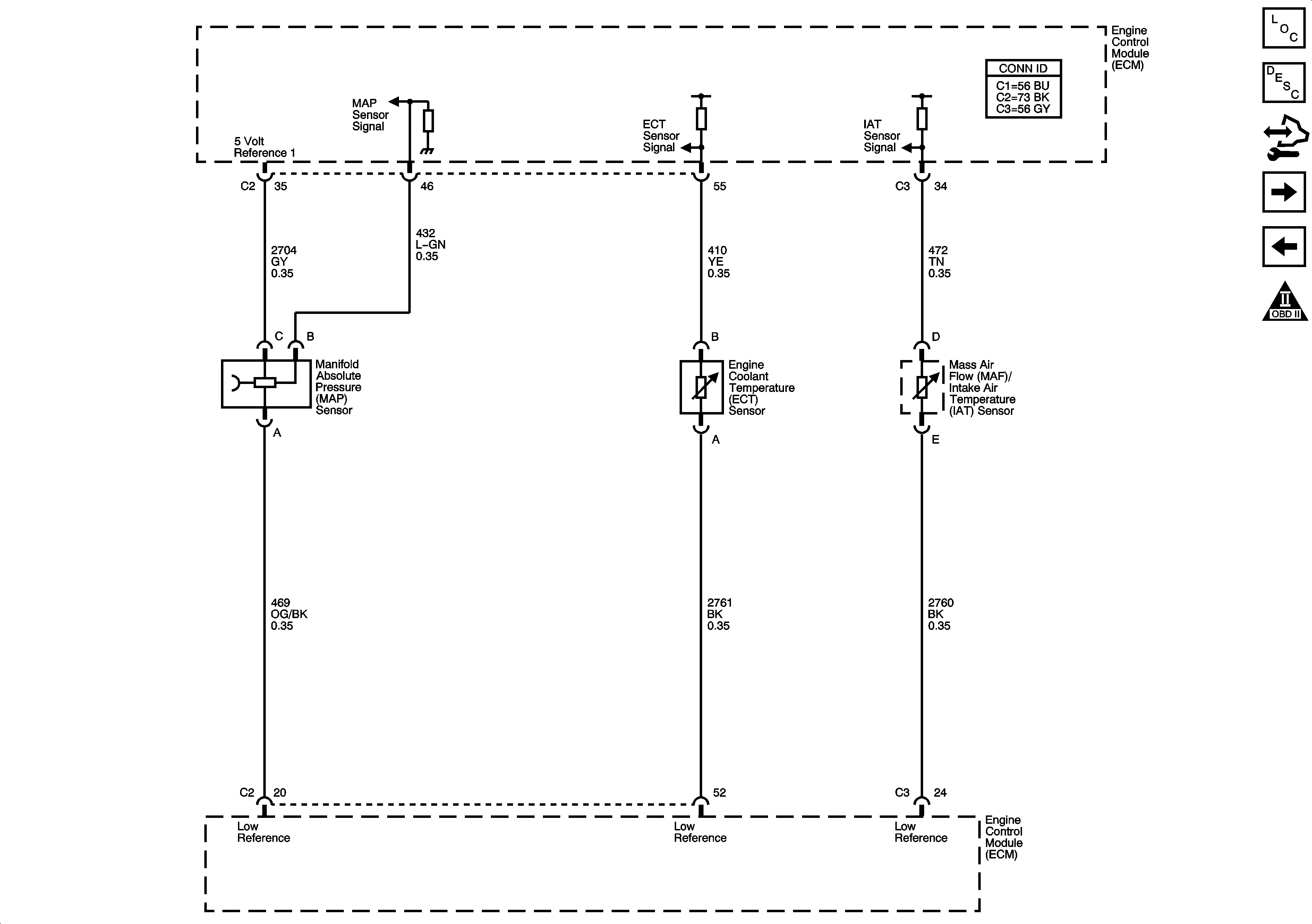
MAP, ECT, and MAF/IAT Sensors


Object Number: 1653978  Size: FS
Master Electrical Component List
Engine Control Module Description
Control Module References
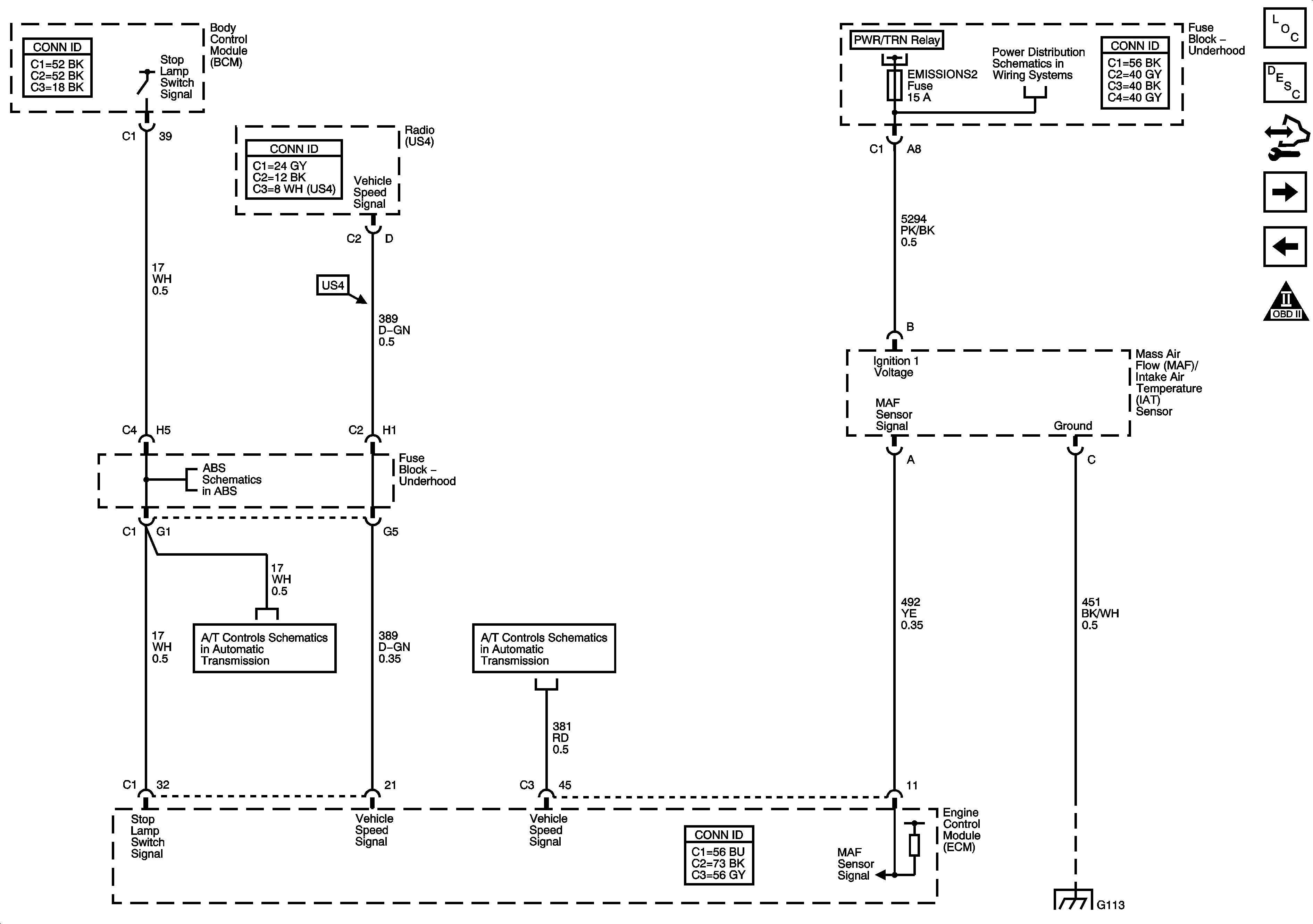
MAF/IAT Sensor, Stop Lamp Switch Signal and VSS
5-Volt and Low Reference Bussing
Engine Controls Schematic Icons
Figure 4:

MAF/IAT Sensor, Stop Lamp Switch Signal and VSS


Object Number: 1653980  Size: FS
Master Electrical Component List
Engine Control Module Description
Control Module References
Heated Oxygen Sensors
MAP, ECT, and MAF/IAT Sensors
Engine Controls Schematic Icons
Fuse Block - Underhood Bussing
EMISSIONS1, EMISSIONS2, A/C COMPRSR Fuses, and A/C CMPRSR Relay
Indicator, ABS, Stability, and Traction Controls
Tap Shift Switches, Stop Lamp Signal, TFT Sensor and TCC, Shift Solenoids
VSS and AT ISS Sensors, Pressure Control Solenoid Valve, and TCC Release Switch
G112 (LS4), AND G113 (LS4)
Figure 5:

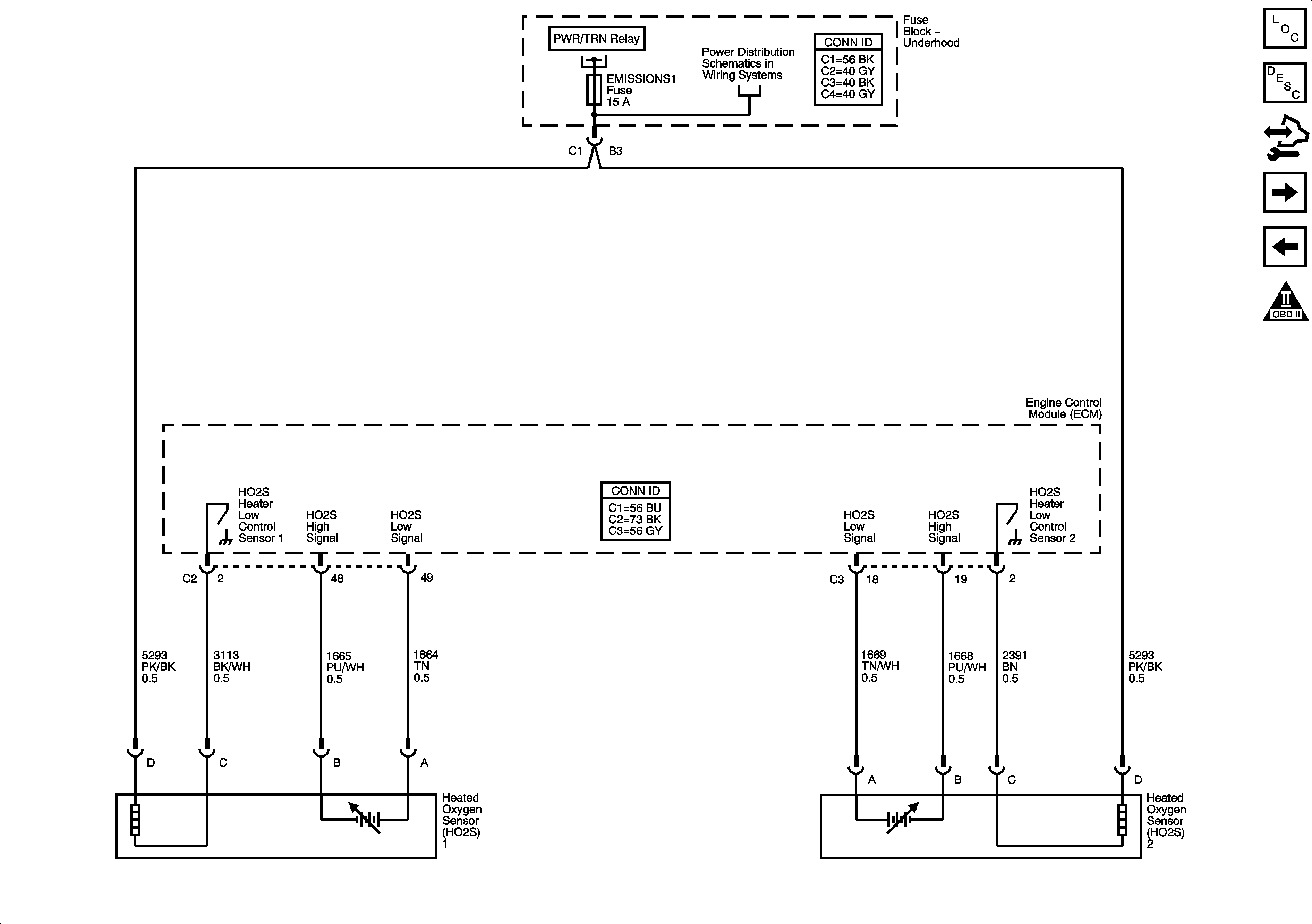
Heated Oxygen Sensors


Object Number: 1653982  Size: FS
Master Electrical Component List
Engine Control Module Description
Control Module References
Electronic Throttle Controls
MAF/IAT Sensor, Stop Lamp Switch Signal and VSS
Engine Controls Schematic Icons
Fuse Block - Underhood Bussing
EMISSIONS1, EMISSIONS2, A/C COMPRSR Fuses, and A/C CMPRSR Relay
Figure 6:

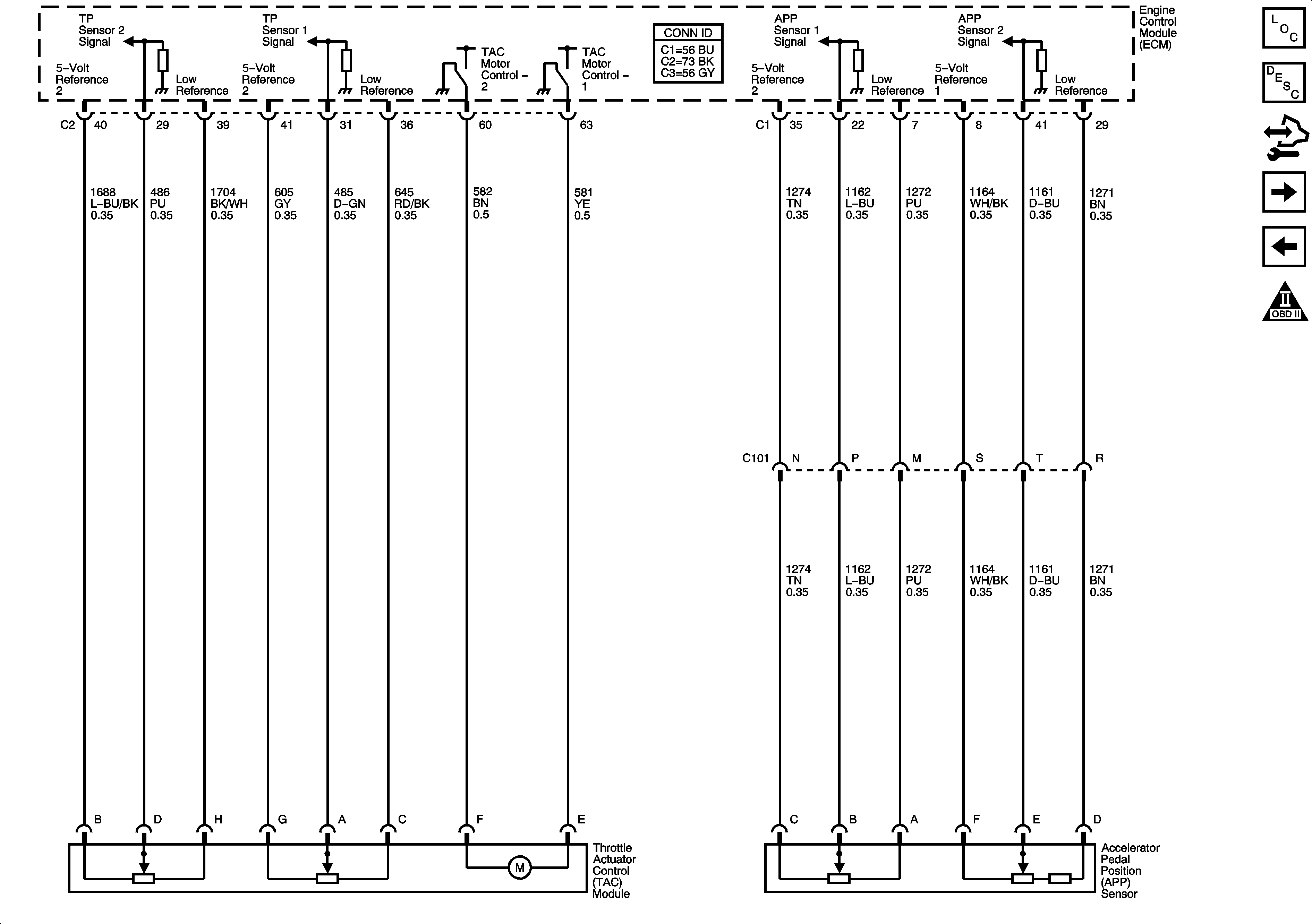
Electronic Throttle Controls


Object Number: 1653987  Size: FS
Master Electrical Component List
Throttle Actuator Control (TAC) System Description
Control Module References
Ignition Controls Bank 1 (Odd) Ignition Coils
Heated Oxygen Sensors
Engine Controls Schematic Icons
Figure 7:

Ignition Controls Bank 1 (Odd) Ignition Coils


Object Number: 1653989  Size: FS
Master Electrical Component List
Engine Control Module Description
Control Module References
Ignition Controls Bank 2 (Even) Ignition Coils
Electronic Throttle Controls
Engine Controls Schematic Icons
Fuse Block - Underhood Bussing
, INJ 2, EMISSION1, EMISSION2 Fuses, and COMPRSR Relay
Indicator, ABS, Stability, and Traction Controls
G112 (LS4), AND G113 (LS4)
Figure 8:

Ignition Controls Bank 2 (Even) Ignition Coils


Object Number: 1653995  Size: FS
Master Electrical Component List
Engine Control Module Description
Control Module References
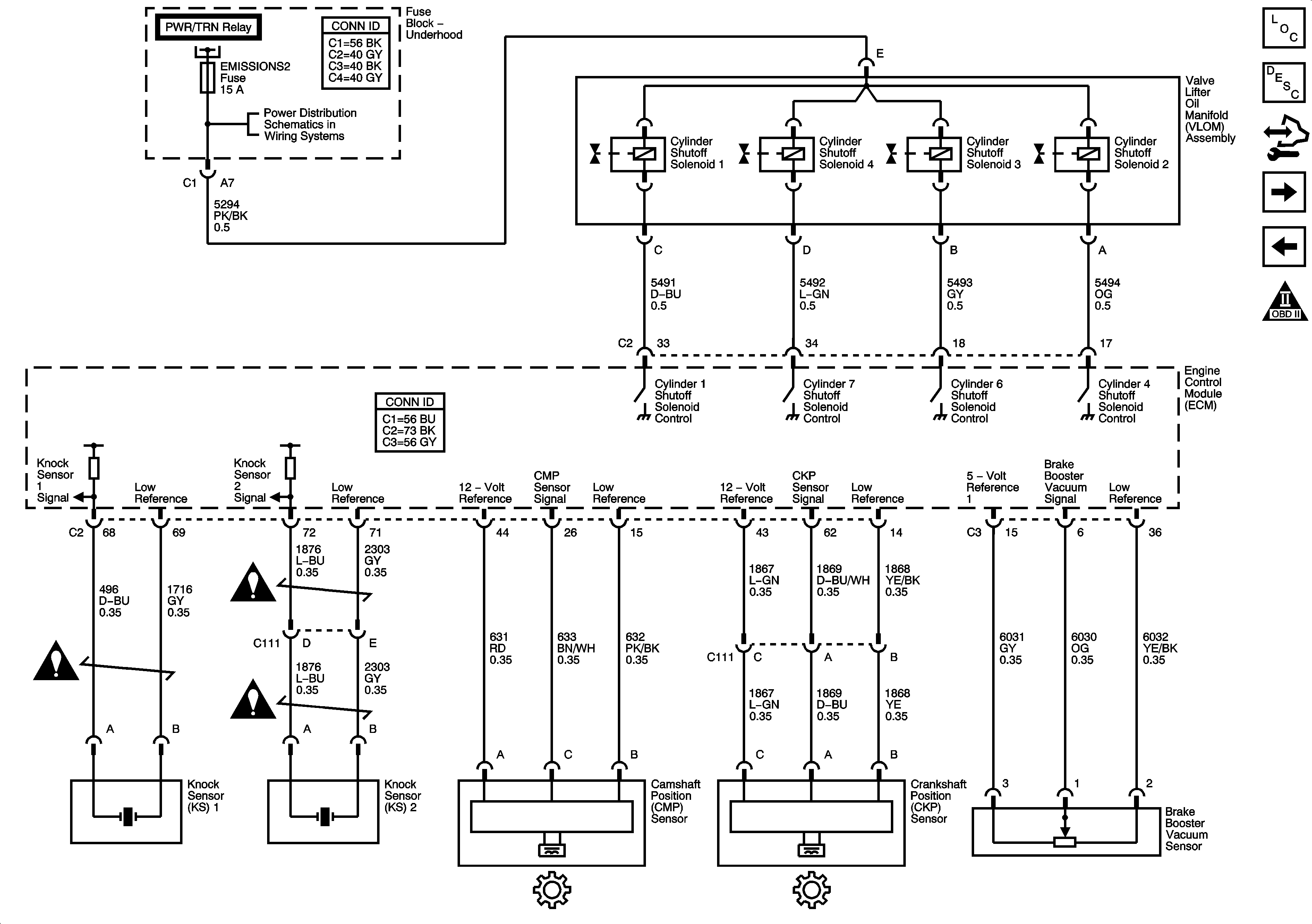
Ignition Controls Knock, CMP, CKP, Brake Booster Vacuum Sensors and Valve Lifter Oil Manifold Assembly
Ignition Controls Bank 1 (Odd) Ignition Coils
Engine Controls Schematic Icons
Fuse Block - Underhood Bussing
, INJ 2, EMISSION1, EMISSION2 Fuses, and COMPRSR Relay
G112 (LS4), AND G113 (LS4)
Figure 9:

Ignition Controls Knock, CMP, CKP, Brake Booster Vacuum Sensors and Valve Lifter Oil Manifold Assembly


Object Number: 1653996  Size: FS
Master Electrical Component List
Engine Control Module Description
Control Module References
Fuel Pump Controls
Ignition Controls Bank 2 (Even) Ignition Coils
Engine Controls Schematic Icons
Fuse Block - Underhood Bussing
Fuse Block Underhood Bussing
Engine Controls Schematic Icons
Figure 10:

Fuel Pump Controls


Object Number: 1654000  Size: FS
Master Electrical Component List
Fuel System Description
Control Module References
Fuel Injectors
Ignition Controls Knock, CMP, CKP, Brake Booster Vacuum Sensors and Valve Lifter Oil Manifold Assembly
Engine Controls Schematic Icons
Fuse Block - Underhood Bussing
G112 (LS4), AND G113 (LS4)
Power, Ground, and Gages
G302
G112 (LS4), AND G113 (LS4)
Figure 11:

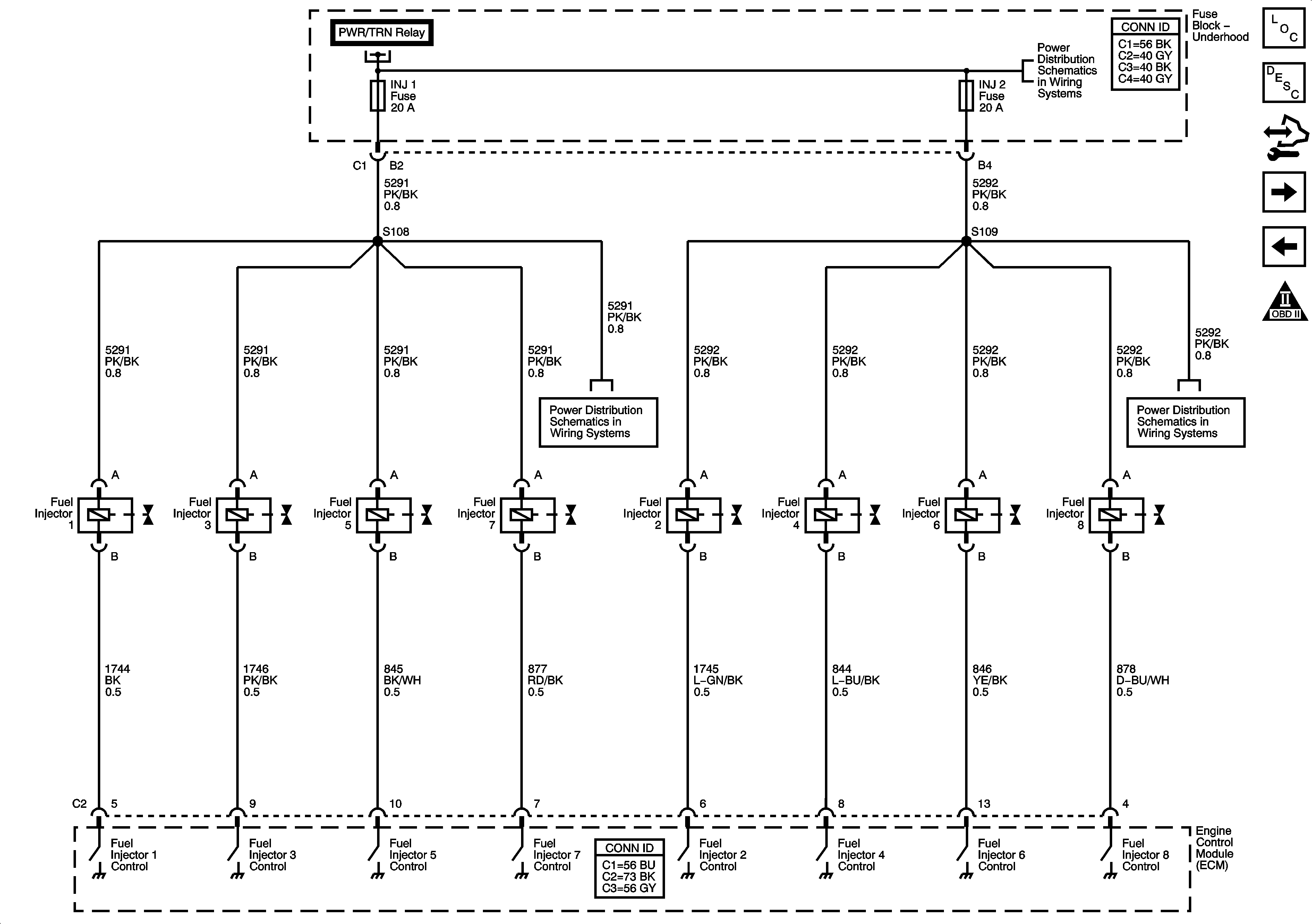
Fuel Injectors


Object Number: 1654003  Size: FS
Master Electrical Component List
Engine Control Module Description
Control Module References
EVAP Solenoids and FTP Sensor
Fuel Pump Controls
Engine Controls Schematic Icons
Fuse Block - Underhood Bussing
, INJ 2, EMISSION1, EMISSION2 Fuses, and COMPRSR Relay
Figure 12:

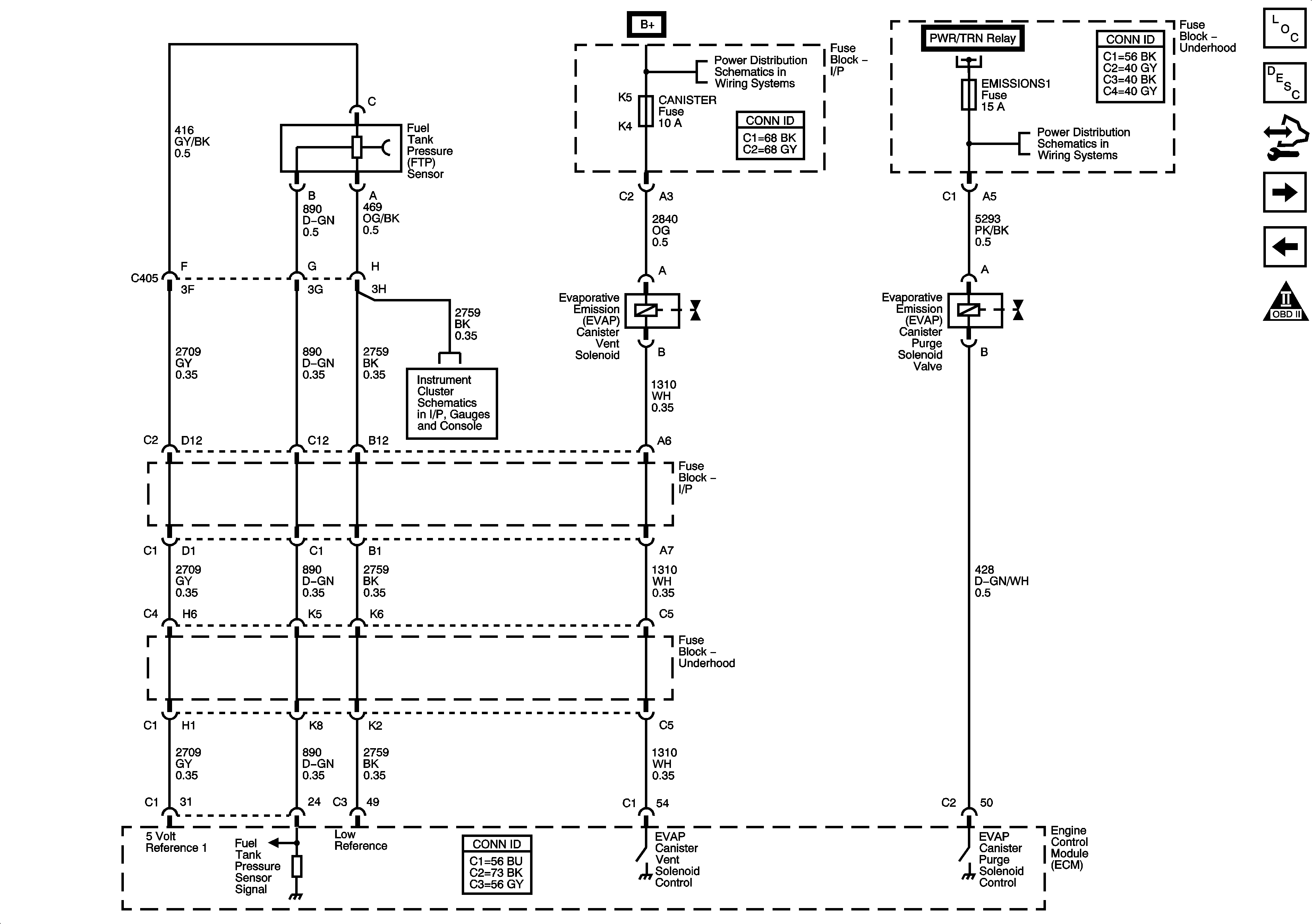
EVAP Solenoids and FTP Sensor


Object Number: 1654006  Size: FS
Master Electrical Component List
Evaporative Emission Control System Description
Control Module References
Controlled/Monitored Subsystem References
Fuel Injectors
Engine Controls Schematic Icons
Power, Ground, and Gages
Fuse Block - Underhood Bussing
EMISSIONS1, EMISSIONS2, A/C COMPRSR Fuses, and A/C CMPRSR Relay
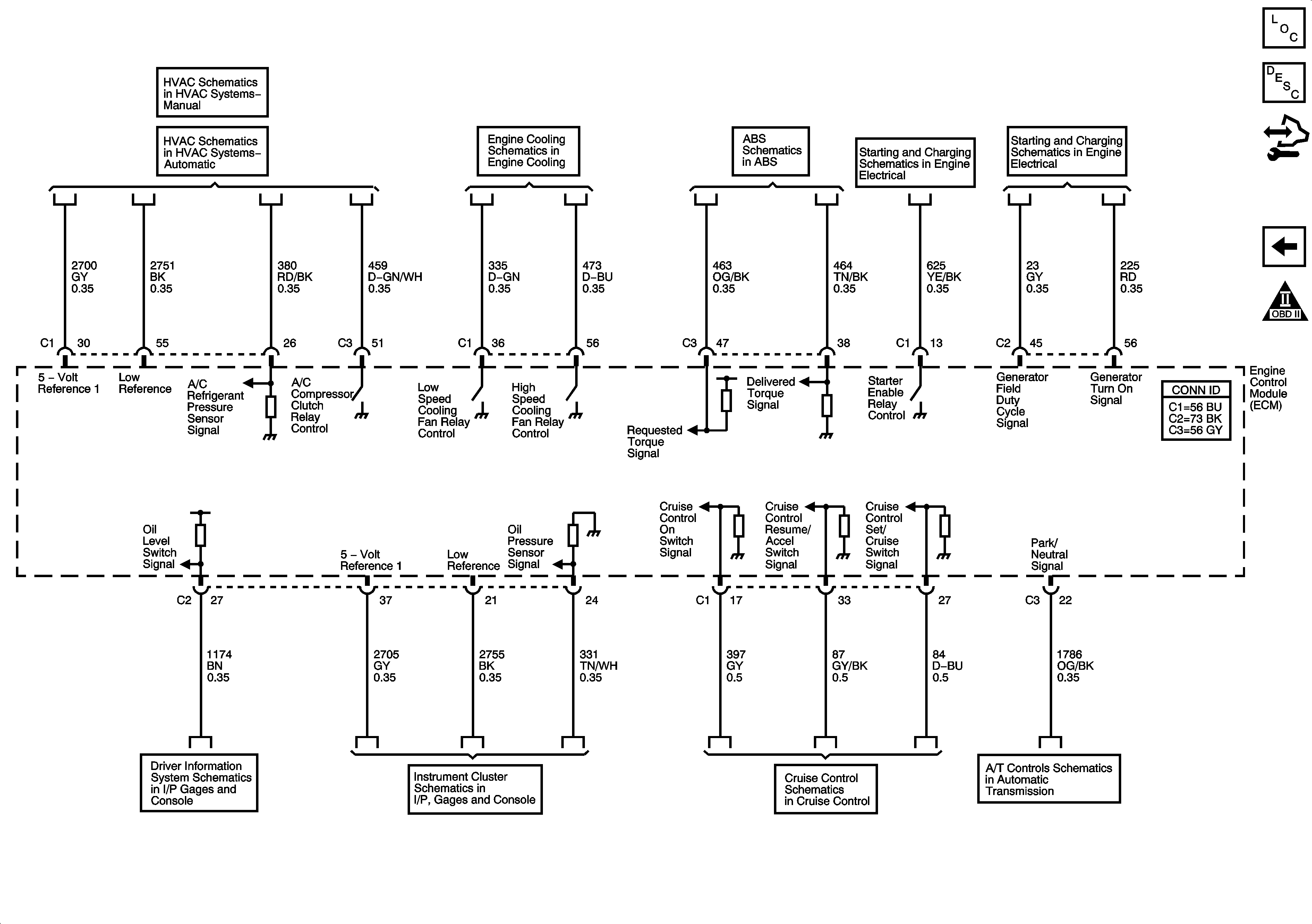
Figure 13:

Controlled/Monitored Subsystem References


Object Number: 1654008  Size: FS
Master Electrical Component List
Engine Control Module Description
Control Module References
EVAP Solenoids and FTP Sensor
Engine Controls Schematic Icons
A/C Compressor Controls
LS4
Indicator, ABS, Stability, and Traction Controls
Starting LS4
Generator
Driver Information System
Indicators
LS4
PRNDL, and IMS Switch