C100 Engine Harness to Transmission Harness (L26/L32)
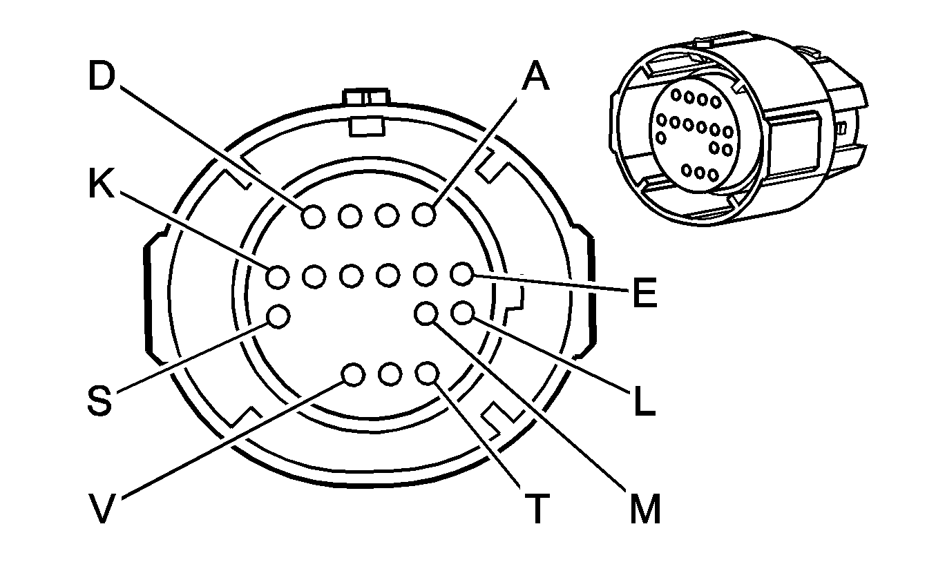
|
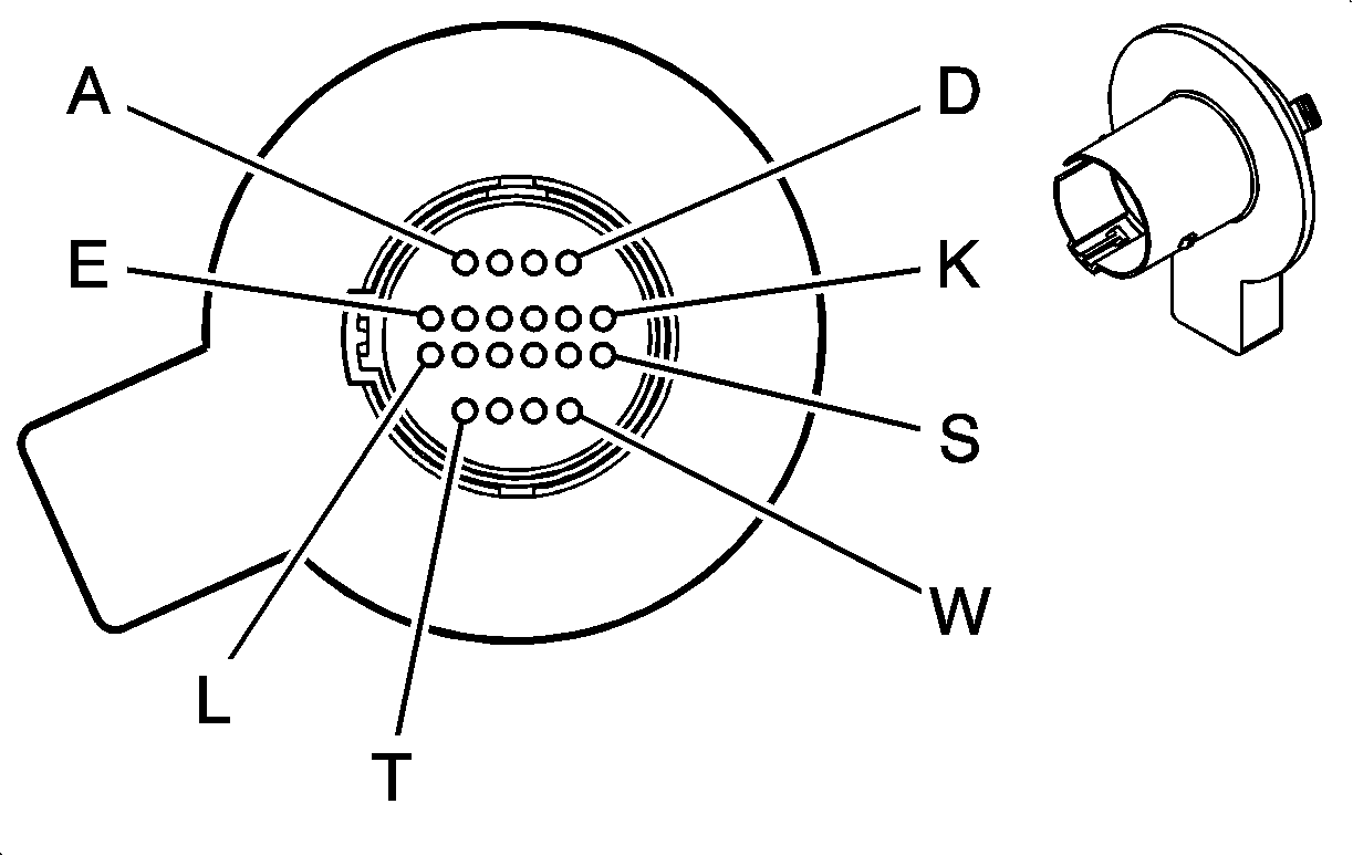
|
Connector Part Information
| Connector Part Information
|
Terminal Part Information
| Terminal Part Information
|
Pin | Wire Color | Circuit No. | Function | Pin | Wire Color | Circuit No. | Function |
|---|---|---|---|---|---|---|---|
A | L-GN | 1222 | 1-2 Shift Solenoid Valve Control | A | L-GN | 1222 | 1-2 Shift Solenoid Valve Control |
B | YE/BK | 1223 | 2-3 Shift Solenoid Valve Control | B | YE | 1223 | 2-3 Shift Solenoid Valve Control |
C | RD/BK | 1228 | PC Solenoid Valve High Control | C | PU | 1228 | PC Solenoid Valve High Control |
D | L-BU/WH | 1229 | PC Solenoid Valve Low Control | D | L-BU | 1229 | PC Solenoid Valve Low Control |
E | PK | 1339 | Ignition 1 Voltage | E | RD | 839 | Ignition 1 Voltage |
F | BK/WH | 771 | Transmission Range Switch Signal A | F | RD/BK | 771 | Transmission Range Switch Signal A |
G | YE | 772 | Transmission Range Switch Signal B | G | D-GN/WH | 772 | Transmission Range Switch Signal B |
H | GY | 773 | Transmission Range Switch Signal C | H | YE/BK | 773 | Transmission Range Switch Signal C |
J | WH | 776 | Transmission Range Switch Signal P | J | GY/WH | 776 | Transmission Range Switch Signal P |
K | BK/WH | 451 | Ground | K | BK/WH | 1050 | Ground |
L | YE/BK | 1227 | TFT Sensor Signal | L | BN | 1227 | TFT Sensor Signal |
M | BK | 452 | Low Reference | M | GY | 452 | Low Reference |
N-R | -- | -- | Not Used | N-R | -- | -- | Not Used |
S | RD/BK | 1230 | A/T ISS High Signal | S | BK | 1230 | A/T ISS High Signal |
T | TN/BK | 422 | TCC Solenoid Valve Control | T | TN | 418 | TCC Solenoid Valve Control |
U | WH | 1804 | TCC Release Switch Signal | U | WH | 1804 | TCC Release Switch Signal |
V | D-BU/WH | 1231 | A/T ISS Low Signal | V | D-GN | 1231 | A/T ISS Low Signal |
W | -- | -- | Not Used | W | -- | -- | Not Used |
C100 Engine Harness to Transmission Harness (LS4)
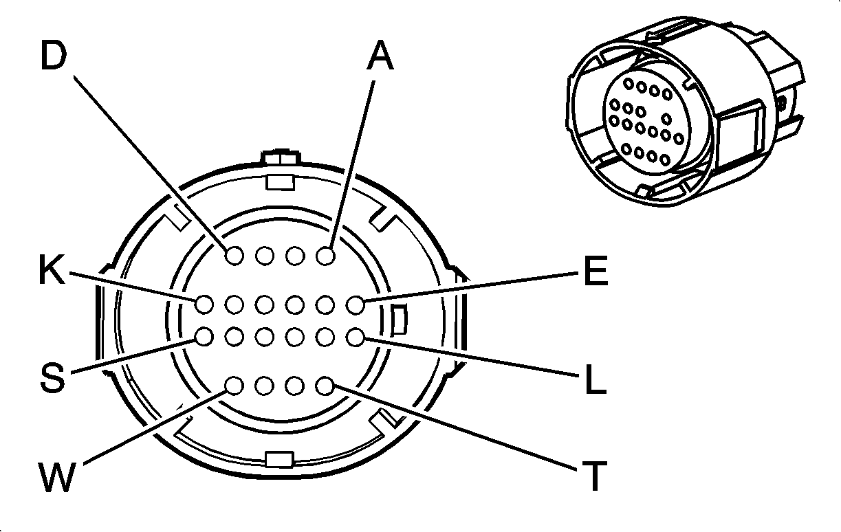
|

|
Connector Part Information
| Connector Part Information
|
Terminal Part Information
| Terminal Part Information
|
Pin | Wire Color | Circuit No. | Function | Pin | Wire Color | Circuit No. | Function |
|---|---|---|---|---|---|---|---|
A | L-GN | 1222 | 1-2 Shift Solenoid Valve Control | A | L-GN | 1222 | 1-2 Shift Solenoid Valve Control |
B | YE/BK | 1223 | 2-3 Shift Solenoid Valve Control | B | YE | 1223 | 2-3 Shift Solenoid Valve Control |
C | RD/BK | 1228 | PC Solenoid Valve High Control | C | PU | 1228 | PC Solenoid Valve High Control |
D | L-BU/WH | 1229 | PC Solenoid Valve Low Control | D | L-BU | 1229 | PC Solenoid Valve Low Control |
E | PK | 1339 | Ignition 1 Voltage | E | RD | 839 | Ignition 1 Voltage |
F | BK/WH | 771 | Transmission Range Switch Signal A | F | RD/BK | 771 | Transmission Range Switch Signal A |
G | YE | 772 | Transmission Range Switch Signal B | G | D-GN/WH | 772 | Transmission Range Switch Signal B |
H | GY | 773 | Transmission Range Switch Signal C | H | YE/BK | 773 | Transmission Range Switch Signal C |
J | WH | 776 | Transmission Range Switch Signal P | J | GY/WH | 776 | Transmission Range Switch Signal P |
K | BK/WH | 251 | Ground | K | BK/WH | 251 | Ground |
L | YE/BK | 1227 | TFT Sensor Signal | L | BN | 1227 | TFT Sensor Signal |
M | BK | 2762 | Low Reference | M | GY | 452 | Low Reference |
N-R | -- | -- | Not Used | N-R | -- | -- | Not Used |
S | RD/BK | 1230 | A/T ISS High Signal | S | BK | 1230 | A/T ISS High Signal |
T | BN | 418 | TCC PWM Solenoid Valve Control | T | TN | 418 | TCC PWM Solenoid Valve Control |
U | WH | 1804 | TCC Release Switch Signal | U | WH | 1804 | TCC Release Switch Signal |
V | D-BU/WH | 1231 | A/T ISS Low Signal | V | D-GN | 1231 | A/T ISS Low Signal |
W | OG/BK | 1786 | Park/Neutral Signal | W | OG | 1786 | Park/Neutral Signal |
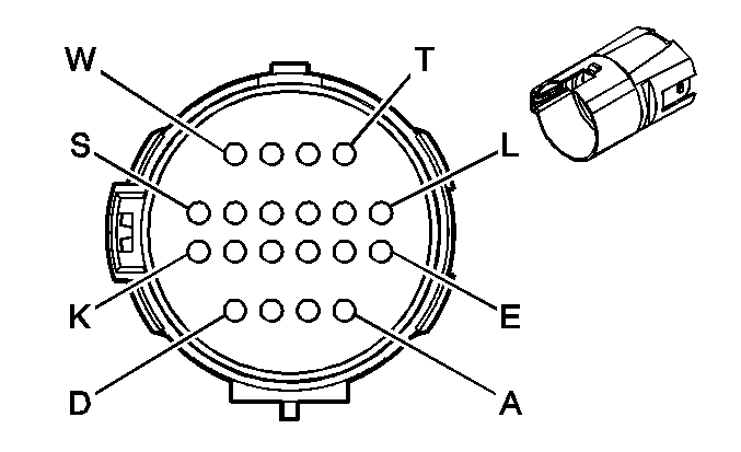
C101 Engine Harness to I/P Harness (L26/L32 w/o JL4)
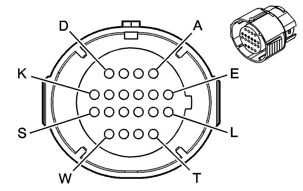
|
|
Connector Part Information
| Connector Part Information
|
Terminal Part Information
| Terminal Part Information
|
Pin | Wire Color | Circuit No. | Function | Pin | Wire Color | Circuit No. | Function |
|---|---|---|---|---|---|---|---|
A | BN/WH | 419 | MIL Control | A | BN/WH | 419 | MIL Control |
B | D-GN | 1049 | PCM Class 2 Serial Data | B | D-GN | 1049 | PCM Class 2 Serial Data |
C | RD | 885 | Left Rear Wheel Speed Sensor Low Reference (JL9) | C | RD | 885 | Left Rear Wheel Speed Sensor Low Reference (JL9) |
D | BK | 884 | Left Rear Wheel Speed Sensor Signal (JL9) | D | BK | 884 | Left Rear Wheel Speed Sensor Signal (JL9) |
E | WH | 883 | Right Rear Wheel Speed Sensor Low Reference (JL9) | E | WH | 883 | Right Rear Wheel Speed Sensor Low Reference (JL9) |
F-K | -- | -- | Unavailable | F-K | -- | -- | Not Used |
L | BN | 882 | Right Rear Wheel Speed Sensor Signal (JL9) | L | BN | 882 | Right Rear Wheel Speed Sensor Signal (JL9) |
M | PU | 1272 | Low Reference | M | PU | 1272 | Low Reference |
N | TN | 1274 | 5-Volt Reference 2 | N | TN | 1274 | 5-Volt Reference 2 |
P | L-BU | 1162 | APP Sensor 1 Signal | P | L-BU | 1162 | APP Sensor 1 Signal |
R | BN | 1271 | Low Reference | R | BN | 1271 | Low Reference |
S | WH/BK | 1164 | 5-Volt Reference 1 | S | WH/BK | 1164 | 5-Volt Reference 1 |
T | D-BU | 1161 | APP Sensor 2 Signal | T | D-BU | 1161 | APP Sensor 2 Signal |
U | L-BU | 1122 | ABS/TCS Class 2 Serial Data | U | L-BU | 1122 | ABS/TCS Class 2 Serial Data |
V-W | -- | -- | Unavailable | V-W | -- | -- | Not Used |
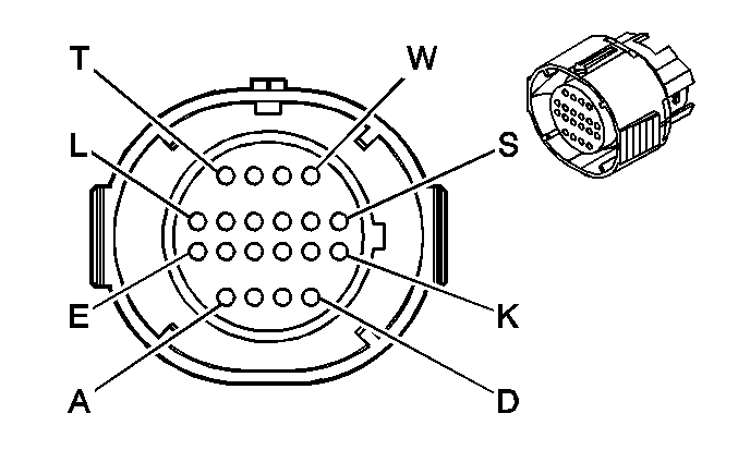
C101 Engine Harness to I/P Harness (L32 w/JL4, LS4)
|

|
Connector Part Information
| Connector Part Information
|
Terminal Part Information
| Terminal Part Information
|
Pin | Wire Color | Circuit No. | Function | Pin | Wire Color | Circuit No. | Function |
|---|---|---|---|---|---|---|---|
A | BN/WH | 419 | MIL Control | A | BN/WH | 419 | MIL Control |
B | D-GN | 1049 | PCM Class 2 Serial Data | B | D-GN | 1049 | PCM Class 2 Serial Data |
C | RD | 885 | Left Rear Wheel Speed Sensor Low Reference | C | RD | 885 | Left Rear Wheel Speed Sensor Low Reference |
D | BK | 884 | Left Rear Wheel Speed Sensor Signal | D | BK | 884 | Left Rear Wheel Speed Sensor Signal |
E | WH | 883 | Right Rear Wheel Speed Sensor Low Reference | E | WH | 883 | Right Rear Wheel Speed Sensor Low Reference |
F | TN/WH | 2500 | High Speed GMLAN Serial Data Bus (+) | F | TN/WH | 2500 | High Speed GMLAN Serial Data Bus (+) |
G | TN | 2501 | High Speed GMLAN Serial Data Bus (-) | G | TN | 2501 | High Speed GMLAN Serial Data Bus (-) |
H | GY/BK | 1798 | Ground | H | GY/BK | 1798 | Ground |
J | D-BU | 716 | Yaw Rate Sensor Signal | J | D-BU | 716 | Yaw Rate Sensor Signal |
K | GY | 930 | 5-Volt Reference | K | GY | 930 | 5-Volt Reference |
L | BN | 882 | Right Rear Wheel Speed Sensor Signal | L | BN | 882 | Right Rear Wheel Speed Sensor Signal |
M | PU | 1272 | Low Reference | M | PU | 1272 | Low Reference |
N | TN | 1274 | 5-Volt Reference A | N | TN | 1274 | 5-Volt Reference A |
P | L-BU | 1162 | APP Sensor 2 Signal | P | L-BU | 1162 | APP Sensor 2 Signal |
R | BN | 1271 | Low Reference | R | BN | 1271 | Low Reference |
S | WH/BK | 1164 | 5-Volt Reference B | S | WH/BK | 1164 | 5-Volt Reference B |
T | D-BU | 1161 | APP Sensor 1 Signal | T | D-BU | 1161 | APP Sensor 1 Signal |
U | L-BU | 1122 | ABS/TCS Class 2 Serial Data | U | L-BU | 1122 | ABS/TCS Class 2 Serial Data |
V | BN/WH | 2086 | Yaw Rate Sensor Test Control | V | BN/WH | 2086 | Yaw Rate Sensor Test Control |
W | L-BU | 715 | Lateral Accelerometer Signal | W | L-BU | 715 | Lateral Accelerometer Signal |
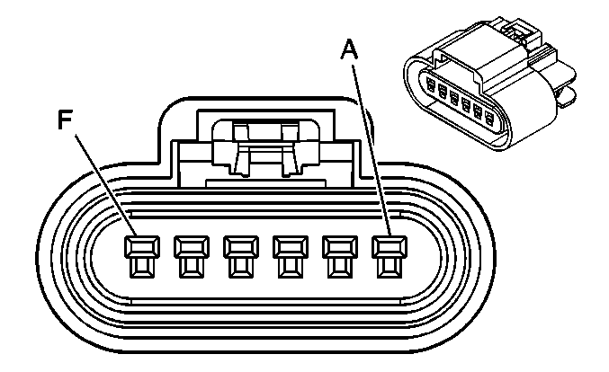
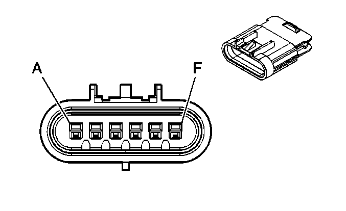
C102 Engine Harness to I/P Harness (LS4)
|
|
Connector Part Information
| Connector Part Information
|
Terminal Part Information
| Terminal Part Information
|
Pin | Wire Color | Circuit No. | Function | Pin | Wire Color | Circuit No. | Function |
|---|---|---|---|---|---|---|---|
A | GY/BK | 87 | Cruise Control Resume/Accel Switch Signal | A | GY/BK | 87 | Cruise Control Resume/Accel Switch Signal |
B | D-BU | 84 | Cruise Control Set/Coast Switch Signal | B | D-BU | 84 | Cruise Control Set/Coast Switch Signal |
C | GY | 397 | Cruise Control On Switch Signal | C | GY | 397 | Cruise Control On Switch Signal |
D | YE | 2361 | SAE J1939 Serial Data Bus (+) | D | YE | 2361 | SAE J1939 Serial Data Bus (+) |
E | D-GN | 2362 | SAE J1939 Serial Data Bus (-) | E | D-GN | 2362 | SAE J1939 Serial Data Bus (-) |
F | -- | -- | Not Used | F | -- | -- | Not Used |
C104 I/P Harness to Engine Harness
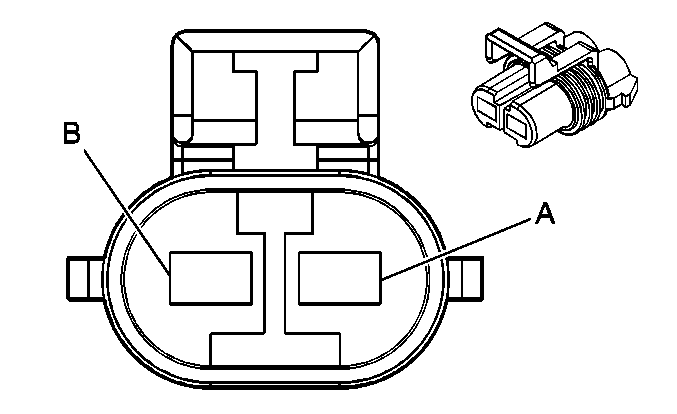
|
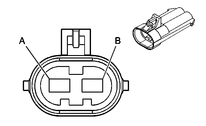
|
Connector Part Information
| Connector Part Information
|
Terminal Part Information
| Terminal Part Information
|
Pin | Wire Color | Circuit No. | Function | Pin | Wire Color | Circuit No. | Function |
|---|---|---|---|---|---|---|---|
A | RD | 1442 | Battery Positive Voltage | A | RD | 1442 | Battery Positive Voltage |
B | OG | 1540 | Battery Positive Voltage (NU3) | B | OG | 1540 | Battery Positive Voltage (NU3) |
C105 Battery Cable Harness to I/P Harness
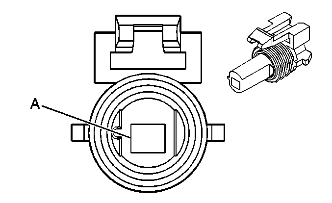
|
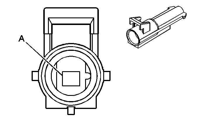
|
Connector Part Information
| Connector Part Information
|
Terminal Part Information
| Terminal Part Information
|
Pin | Wire Color | Circuit No. | Function | Pin | Wire Color | Circuit No. | Function |
|---|---|---|---|---|---|---|---|
A | BK/WH | 151 | Ground | A | BK/WH | 151 | Ground |
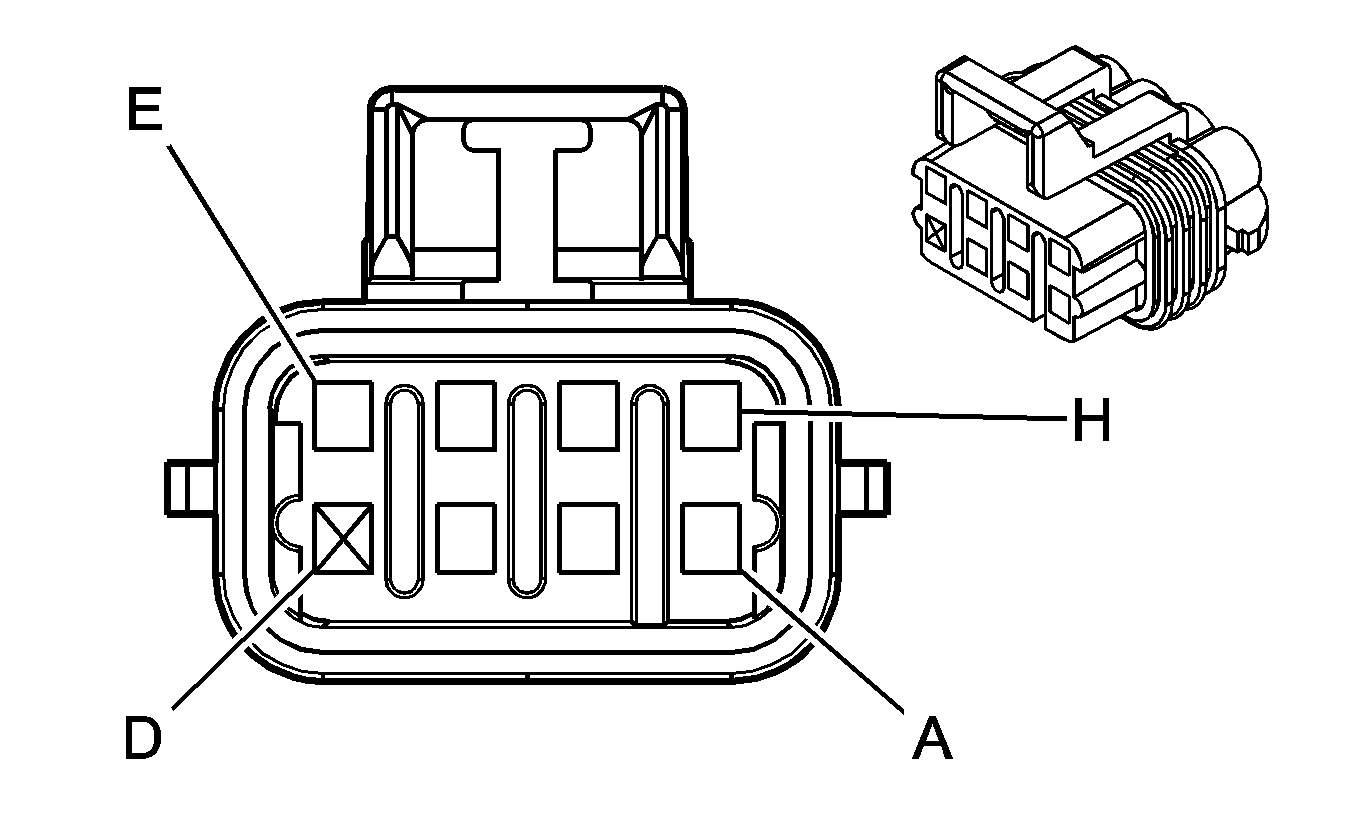
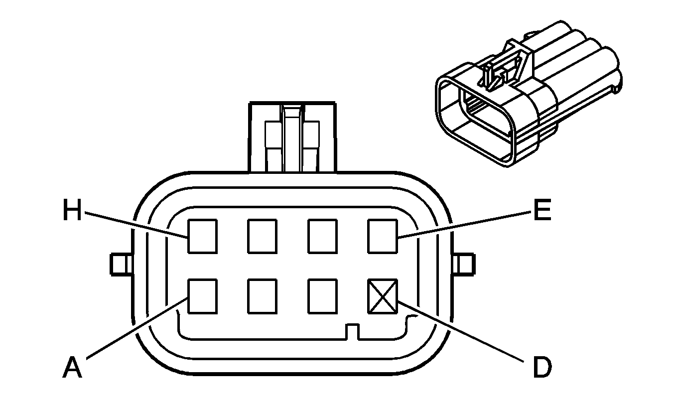
C107 Engine Harness to Front Ignition Coil Harness (LS4)
|
|
Connector Part Information
| Connector Part Information
|
Terminal Part Information
| Terminal Part Information
|
Pin | Wire Color | Circuit No. | Function | Pin | Wire Color | Circuit No. | Function |
|---|---|---|---|---|---|---|---|
A | BK | 51 | Ground | A | BK | 151 | Ground |
B | RD | 2127 | IC 7 Control | B | RD | 2127 | IC 7 Control |
C | D-GN | 2125 | IC 5 Control | C | D-GN | 2125 | IC 5 Control |
D | -- | -- | Not Used | D | -- | -- | Not Used |
E | BN | 2129 | Low Reference | E | BN | 2129 | Low Reference |
F | L-BU | 2123 | IC 3 Control | F | L-BU | 2123 | IC 3 Control |
G | PU | 2121 | IC 1 Control | G | PU | 2121 | IC 1 Control |
H | PK/BK | 5291 | Ignition 1 Voltage | H | PK | 39 | Ignition 1 Voltage |
C108 Engine Harness to Rear Ignition Coil Harness (LS4)

|

|
Connector Part Information
| Connector Part Information
|
Terminal Part Information
| Terminal Part Information
|
Pin | Wire Color | Circuit No. | Function | Pin | Wire Color | Circuit No. | Function |
|---|---|---|---|---|---|---|---|
A | BK | 51 | Ground | A | BK | 151 | Ground |
B | RD/WH | 2122 | IC 2 Control | B | RD | 2127 | IC 2 Control |
C | D-GN/WH | 2124 | IC 4 Control | C | D-GN | 2125 | IC 4 Control |
D | -- | -- | Not Used | D | -- | -- | Not Used |
E | BN/WH | 2130 | Low Reference | E | BN | 2129 | Low Reference |
F | L-BU/WH | 2126 | IC 6 Control | F | L-BU | 2123 | IC 6 Control |
G | PU/WH | 2128 | IC 8 Control | G | PU | 2121 | IC 8 Control |
H | PK/BK | 5292 | Ignition 1 Voltage | H | PK | 39 | Ignition 1 Voltage |
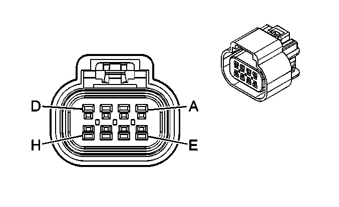
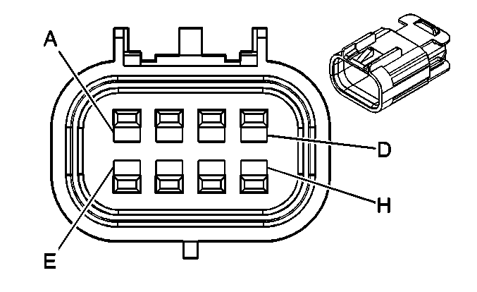
C110 Engine Harness to Ignition Control Module (ICM) Wiring Harness
|
|
Connector Part Information
| Connector Part Information
|
Terminal Part Information
| Terminal Part Information
|
Pin | Wire Color | Circuit No. | Function | Pin | Wire Color | Circuit No. | Function |
|---|---|---|---|---|---|---|---|
A | WH | 423 | IC Timing Control | A | WH | 423 | IC Timing Control |
B | TN/BK | 424 | IC Timing Signal | B | TN/BK | 424 | IC Timing Signal |
C | L-BU/BK | 647 | Medium Resolution Engine Speed Signal | C | L-BU/BK | 647 | Medium Resolution Engine Speed Signal |
D | PU/WH | 430 | Low Resolution Engine Speed Signal | D | PU/WH | 430 | Low Resolution Engine Speed Signal |
E | -- | -- | Not Used | E | WH | 121 | Engine Speed Signal |
F | BK | 630 | Camshaft Position Signal | F | BK | 630 | Camshaft Position Signal |
G | RD/BK | 453 | Low Reference | G | RD/BK | 453 | Low Reference |
H | PK | 239 | Ignition 1 Voltage | H | PK | 239 | Ignition 1 Voltage |
C111 Crankshaft Sensor Jumper Harness to Engine Harness (LS4)
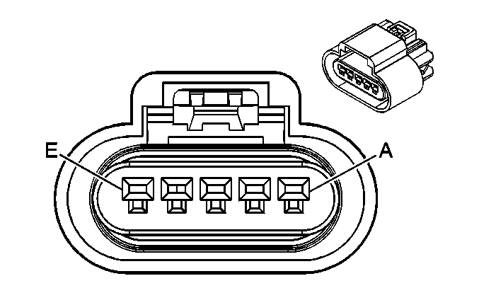
|
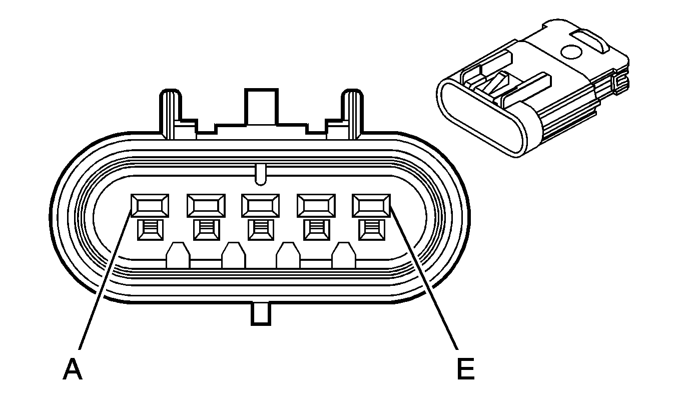
|
Connector Part Information
| Connector Part Information
|
Terminal Part Information
| Terminal Part Information
|
Pin | Wire Color | Circuit No. | Function | Pin | Wire Color | Circuit No. | Function |
|---|---|---|---|---|---|---|---|
A | D-BU | 1869 | CKP Sensor Signal | A | D-BU/WH | 1869 | CKP Sensor Signal |
B | YE | 1868 | Low Reference | B | YE | 1868 | Low Reference |
C | L-GN | 1867 | 12-Volt Reference | C | L-GN | 1867 | 12-Volt Reference |
D | L-BU | 1876 | Knock Sensor 2 Signal | D | L-BU | 1876 | Knock Sensor 2 Signal |
E | GY | 2303 | Knock Sensor 2 Signal | E | GY | 2303 | Knock Sensor 2 Signal |
C120 Forward Lamp Harness to I/P Harness (L26/L32)

|

|
Connector Part Information
| Connector Part Information
|
Terminal Part Information
| Terminal Part Information
|
Pin | Wire Color | Circuit No. | Function | Pin | Wire Color | Circuit No. | Function |
|---|---|---|---|---|---|---|---|
A | L-GN/BK | 735 | Ambient Air Temperature Sensor Signal | A | L-GN/BK | 735 | Ambient Air Temperature Sensor Signal |
B | YE | 61 | Low Reference | B | YE | 61 | Low Reference |
C | GY | 2260 | Low Reference | C | GY | 2260 | Low Reference |
D | YE | 2160 | Front End Sensor Signal - Left | D | YE | 2160 | Front End Sensor Signal - Left |
E | PU | 2612 | Low Reference | E | PU | 2612 | Low Reference |
F | WH/BK | 2611 | Front End Sensor Signal - Right | F | WH/BK | 2611 | Front End Sensor Signal - Right |
C120 Forward Lamp Harness to I/P Harness (LS4)
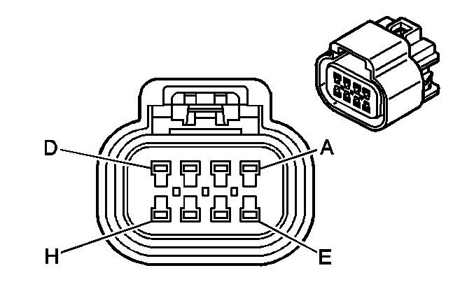
|

|
Connector Part Information
| Connector Part Information
|
Terminal Part Information
| Terminal Part Information
|
Pin | Wire Color | Circuit No. | Function | Pin | Wire Color | Circuit No. | Function |
|---|---|---|---|---|---|---|---|
A | GY | 2260 | Low Reference | A | GY | 2260 | Low Reference |
B | L-GN/BK | 735 | Ambient Air Temperature Sensor Signal | B | L-GN/BK | 735 | Ambient Air Temperature Sensor Signal |
C | PU | 2612 | Low Reference | C | PU | 2612 | Low Reference |
D | -- | -- | Not Used | D | -- | -- | Not Used |
E | YE | 2160 | Front End Sensor Signal - Left | E | YE | 2160 | Front End Sensor Signal - Left |
F | YE | 61 | Low Reference | F | YE | 61 | Low Reference |
G | WH/BK | 2611 | Front End Sensor Signal - Right | G | WH/BK | 2611 | Front End Sensor Signal - Right |
H | -- | -- | Not Used | H | -- | -- | Not Used |
C125 Engine Harness to Knock Sensor Jumper Harness

|
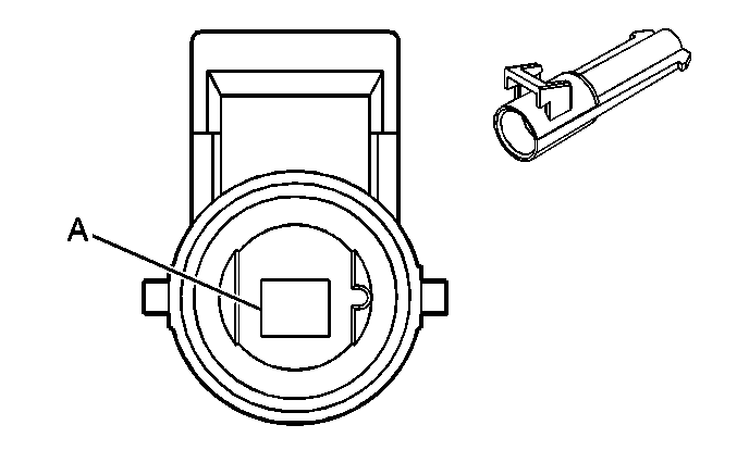
|
Connector Part Information
| Connector Part Information
|
Terminal Part Information
| Terminal Part Information
|
Pin | Wire Color | Circuit No. | Function | Pin | Wire Color | Circuit No. | Function |
|---|---|---|---|---|---|---|---|
A | L-BU | 1876 | Knock Sensor 2 Signal | A | D-BU | 1876 | Knock Sensor 2 Signal |
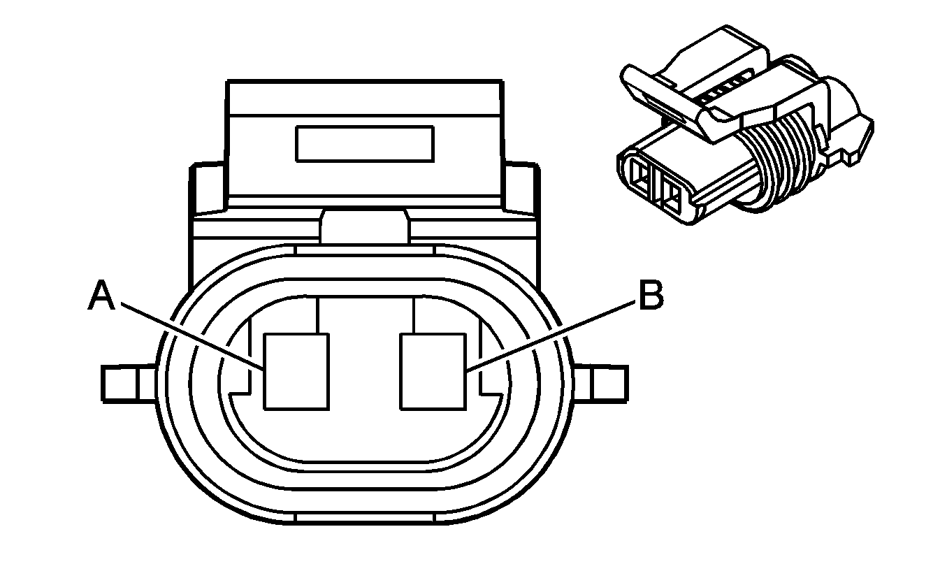
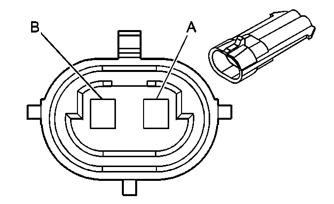
C126 Engine Coolant Temperature (ECT) Sensor Jumper Harness to Engine Harness
|
|
Connector Part Information
| Connector Part Information
|
Terminal Part Information
| Terminal Part Information
|
Pin | Wire Color | Circuit No. | Function | Pin | Wire Color | Circuit No. | Function |
|---|---|---|---|---|---|---|---|
A | BK | 410 | ECT Sensor Signal | A | YE | 410 | ECT Sensor Signal |
B | YE | 2761 | Low Reference | B | BK | 2761 | Low Reference |
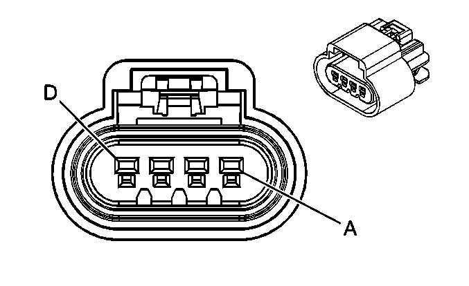
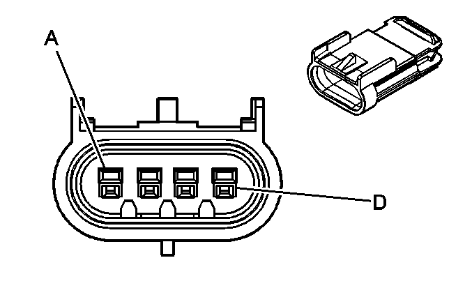
C141 Forward Lamp Harness to Left Front Headlamp Harness
|
|
Connector Part Information
| Connector Part Information
|
Terminal Part Information
| Terminal Part Information
|
Pin | Wire Color | Circuit No. | Function | Pin | Wire Color | Circuit No. | Function |
|---|---|---|---|---|---|---|---|
A | D-GN/WH | 711 | Left Headlamp High Beam Supply Voltage | A | D-GN | 711 | Left Headlamp High Beam Supply Voltage |
B | YE | 712 | Left Headlamp Low Beam Supply Voltage | B | YE | 712 | Left Headlamp Low Beam Supply Voltage |
C | BN | 9 | Park Lamp Supply Voltage | C | BN | 9 | Park Lamp Supply Voltage |
D | BK | 1350 | Ground | D | BK | 1350 | Ground |
C142 Forward Lamp Harness to Right Front Headlamp Harness

|

|
Connector Part Information
| Connector Part Information
|
Terminal Part Information
| Terminal Part Information
|
Pin | Wire Color | Circuit No. | Function | Pin | Wire Color | Circuit No. | Function |
|---|---|---|---|---|---|---|---|
A | L-GN/BK | 311 | Right Headlamp High Beam Supply Voltage | A | D-GN | 311 | Right Headlamp High Beam Supply Voltage |
B | TN/WH | 312 | Right Headlamp Low Beam Supply Voltage | B | YE | 312 | Right Headlamp Low Beam Supply Voltage |
C | BN | 9 | Park Lamp Supply Voltage | C | BN | 9 | Park Lamp Supply Voltage |
D | BK | 1250 | Ground | D | BK | 1250 | Ground |
C143 Forward Lamp Harness to Left Front Turn Signal Harness
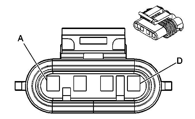
|
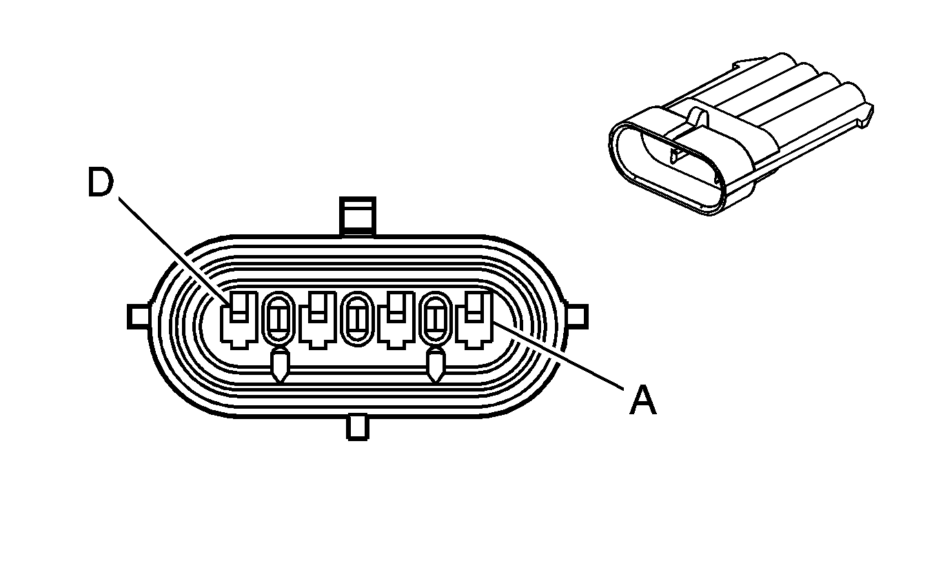
|
Connector Part Information
| Connector Part Information
|
Terminal Part Information
| Terminal Part Information
|
Pin | Wire Color | Circuit No. | Function | Pin | Wire Color | Circuit No. | Function |
|---|---|---|---|---|---|---|---|
A | L-BU/WH | 1314 | Left Front Turn Signal Lamp Supply Voltage | A | L-BU/WH | 1314 | Left Front Turn Signal Lamp Supply Voltage |
B | BN | 9 | Park Lamp Supply Voltage | B | BN | 9 | Park Lamp Supply Voltage |
C | PU | 34 | Fog Lamp Supply Voltage | C | PU | 34 | Fog Lamp Supply Voltage |
D | BK | 1350 | Ground | D | BK | 1350 | Ground |
C144 Forward Lamp Harness to Right Front Turn Signal Harness

|

|
Connector Part Information
| Connector Part Information
|
Terminal Part Information
| Terminal Part Information
|
Pin | Wire Color | Circuit No. | Function | Pin | Wire Color | Circuit No. | Function |
|---|---|---|---|---|---|---|---|
A | L-BU/WH | 1314 | Right Front Turn Signal Lamp Supply Voltage | A | D-BU/WH | 1315 | Right Front Turn Signal Lamp Supply Voltage |
B | BN | 9 | Park Lamp Supply Voltage | B | BN | 9 | Park Lamp Supply Voltage |
C | PU | 34 | Fog Lamp Supply Voltage | C | PU | 34 | Fog Lamp Supply Voltage |
D | BK | 1250 | Ground | D | BK | 1250 | Ground |
C200 Body Harness to I/P Harness
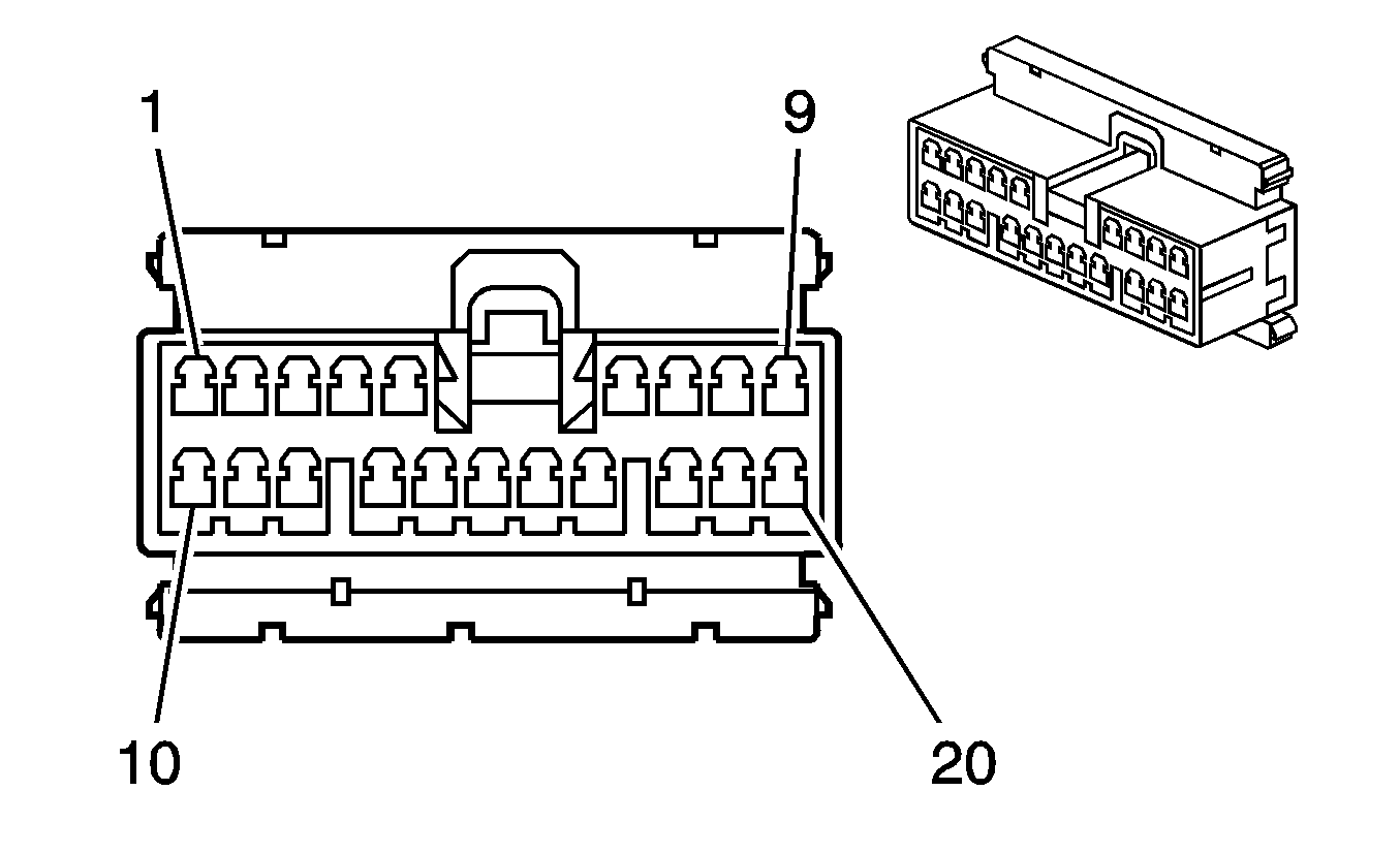
|
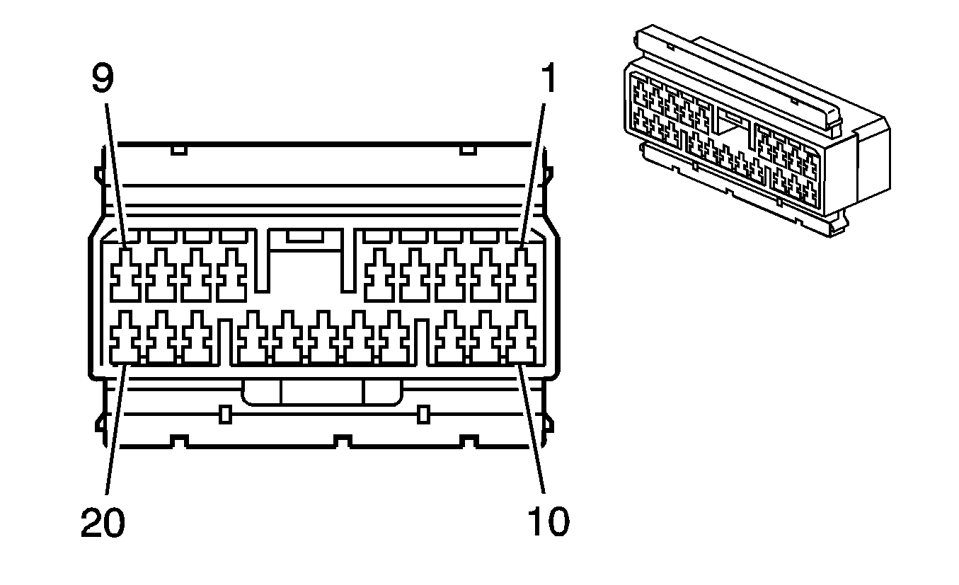
|
Connector Part Information
| Connector Part Information
|
Terminal Part Information
| Terminal Part Information
|
Pin | Wire Color | Circuit No. | Function | Pin | Wire Color | Circuit No. | Function |
|---|---|---|---|---|---|---|---|
1 | BN | 882 | Right Rear Wheel Speed Sensor Signal (JL9) | 1 | BN | 882 | Right Rear Wheel Speed Sensor Signal |
2 | BK | 884 | Left Rear Wheel Speed Sensor Signal (JL9) | 2 | BK | 884 | Left Rear Wheel Speed Sensor Signal |
3 | WH | 5075 | Current Sensor Voltage | 3 | WH | 5075 | Current Sensor Voltage |
4 | GY | 2260 | Front End Sensor - Signal | 4 | GY | 2260 | Front End Sensor - Signal |
5 | YE | 2160 | Front End Sensor - Voltage | 5 | YE | 2160 | Front End Sensor - Voltage |
6 | GY | 655 | Cellular Microphone Signal (UE1, US4) | 6 | GY | 655 | Cellular Microphone Signal (UE1, US4) |
7 | BARE | 1705 | Shielded Ground (UE1, US4) | 7 | BARE | 1705 | Shielded Ground (UE1, US4) |
8 | -- | -- | Not Used | 8 | -- | -- | Not Used |
9 | RD | 885 | Left Rear Wheel Speed Sensor Low Reference (JL9) | 9 | RD | 885 | Left Rear Wheel Speed Sensor Low Reference |
10 | WH | 883 | Right Rear Wheel Speed Sensor Low Reference (JL9) | 10 | WH | 883 | Right Rear Wheel Speed Sensor Low Reference |
11 | D-GN/WH | 2514 | Keypad Signal (UE1) | 11 | D-GN/WH | 2514 | Keypad Signal (UE1) |
12 | L-GN/BK | 2515 | Keypad Supply Voltage (UE1) | 12 | L-GN/BK | 2515 | Keypad Supply Voltage (UE1) |
13 | YE/BK | 2516 | Keypad Green LED Signal (UE1) | 13 | YE/BK | 2516 | Keypad Green LED Signal (UE1) |
14 | BN/WH | 2517 | Keypad Red LED Signal (UE1) | 14 | BN/WH | 2517 | Keypad Red LED Signal (UE1) |
15 | PK | 1045 | RFA Class 2 Serial Data | 15 | PK | 1045 | RFA Class 2 Serial Data |
16 | -- | -- | Not Used | 16 | -- | -- | Not Used |
17 | BARE | 814 | Drain Wire (U2K) | 17 | BARE | 814 | Drain Wire |
18 | BN/WH | 367 | Left Audio Signal (+) (U2K) | 18 | BN/WH | 367 | Left Audio Signal (+) |
19 | D-GN/WH | 368 | Right Audio Signal (+) (U2K) | 19 | D-GN/WH | 368 | Right Audio Signal (+) |
20 | BK/WH | 372 | Audio Common (U2K) | 20 | BK/WH | 372 | Audio Common |
C201 Steering Column Harness to I/P Harness
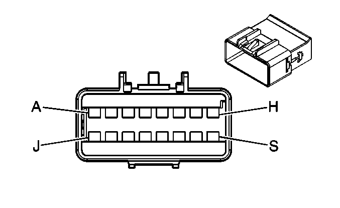
|
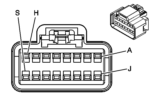
|
Connector Part Information
| Connector Part Information
|
Terminal Part Information
| Terminal Part Information
|
Pin | Wire Color | Circuit No. | Function | Pin | Wire Color | Circuit No. | Function |
|---|---|---|---|---|---|---|---|
A | BK/WH | 1551 | Ground | A | BK/WH | 1551 | Ground |
B | PK | 1539 | Ignition 1 Voltage | B | PK | 1539 | Ignition 1 Voltage |
C | GY | 1884 | Cruise Control Switch Signal | C | GY | 1884 | Cruise Control Switch Signal |
D | -- | -- | Not Used | D | -- | -- | Not Used |
E | PU | 1375 | Remote Radio Control Supply Voltage (UK3) | E | PU | 1375 | Remote Radio Control Supply Voltage (UK3) |
F | GY/BK | 1458 | Instrument Panel Lamp Supply Voltage (UK3) | F | GY/BK | 1458 | Instrument Panel Lamp Supply Voltage (UK3) |
G | D-BU | 1796 | Steering Wheel Controls Signal (UK3) | G | D-BU | 1796 | Steering Wheel Controls Signal (UK3) |
H | BK | 1450 | Ground (UK3) | H | BK | 150 | Ground |
J | -- | -- | Not Used | J | -- | -- | Not Used |
K | YE | 1996 | Remote Shift Selector Signal (UK3) | K | YE | 1996 | Remote Shift Selector Signal (KB7) |
L-S | -- | -- | Not Used | L-S | -- | -- | Not Used |
C208 (JL4) I/P Harness to Body Harness
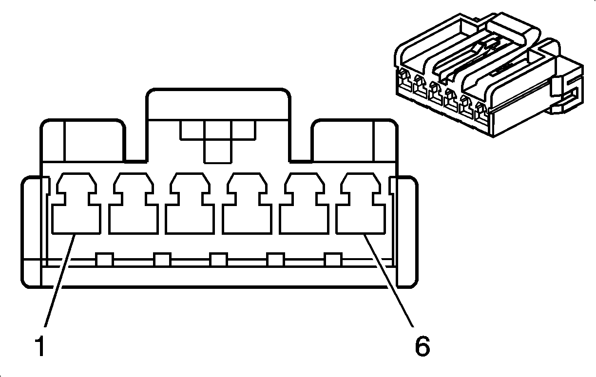
|
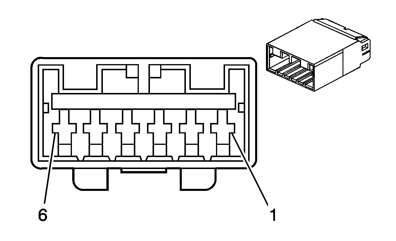
|
Connector Part Information
| Connector Part Information
|
Terminal Part Information
| Terminal Part Information
|
Pin | Wire Color | Circuit No. | Function | Pin | Wire Color | Circuit No. | Function |
|---|---|---|---|---|---|---|---|
1 | PK | 1039 | Ignition 1 Voltage | 1 | PK | 1039 | Ignition 1 Voltage |
2 | GY/BK | 1798 | Ground | 2 | GY/BK | 1798 | Ground |
3 | D-BU | 716 | Yaw Rate Sensor Signal | 3 | D-BU | 716 | Yaw Rate Sensor Signal |
4 | GY | 930 | 5-Volt Reference | 4 | GY | 930 | 5-Volt Reference |
5 | BN/WH | 2086 | Yaw Rate Sensor Test Control | 5 | BN/WH | 2086 | Yaw Rate Sensor Test Control |
6 | L-BU | 715 | Lateral Accelerometer Signal | 6 | L-BU | 715 | Lateral Accelerometer Signal |
C210 (C67) HVAC Harness to I/P Harness
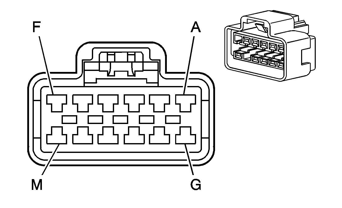
|
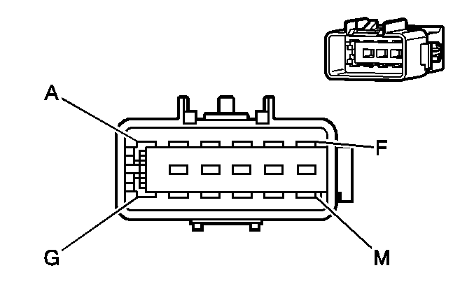
|
Connector Part Information
| Connector Part Information
|
Terminal Part Information
| Terminal Part Information
|
Pin | Wire Color | Circuit No. | Function | Pin | Wire Color | Circuit No. | Function |
|---|---|---|---|---|---|---|---|
A | BK/WH | 1551 | Ground | A | BK/WH | 1551 | Ground |
B | -- | -- | Not Used | B | BK | 150 | Ground |
C | PK | 739 | Ignition 1 Voltage | C | PK | 739 | Ignition 1 Voltage |
D-E | -- | -- | Not Used | D-E | -- | -- | Not Used |
F | OG | 1040 | Battery Positive Voltage | F | OG | 1040 | Battery Positive Voltage |
G | GY | 8 | Instrument Panel Lamp Supply Voltage | G | GY | 8 | Instrument Panel Lamp Supply Voltage |
H | RD | 442 | Battery Positive Voltage | H | RD | 442 | Battery Positive Voltage |
J | BK | 1450 | Ground | J | BK | 150 | Ground |
K | WH | 1038 | HVAC Class 2 Serial Data | K | WH | 1038 | HVAC Class 2 Serial Data |
L-M | -- | -- | Not Used | L-M | -- | -- | Not Used |
C210 (CJ2) HVAC Harness to I/P Harness
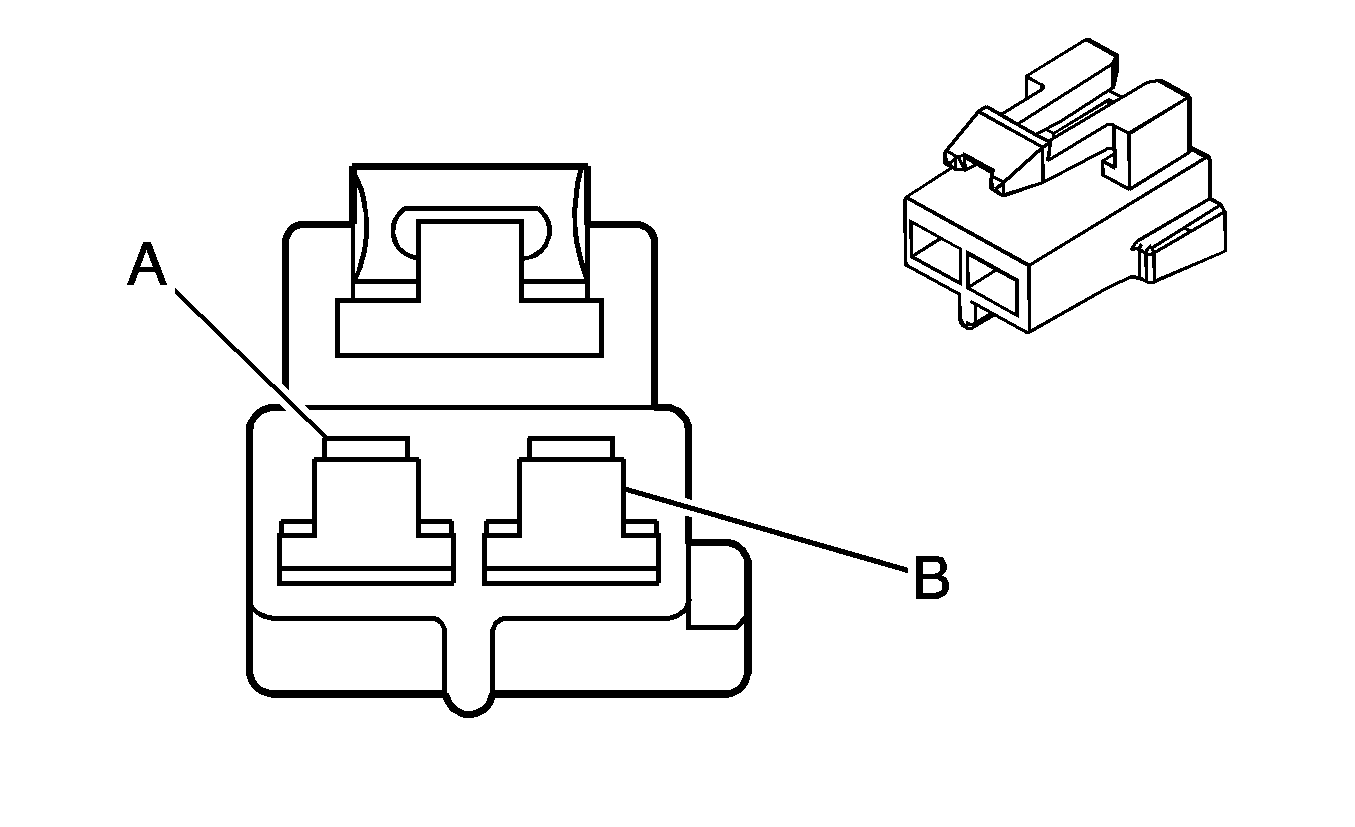
|
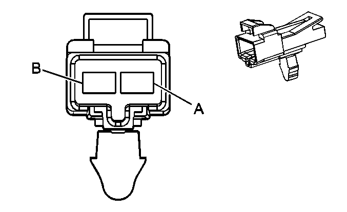
|
Connector Part Information
| Connector Part Information
|
Terminal Part Information
| Terminal Part Information
|
Pin | Wire Color | Circuit No. | Function | Pin | Wire Color | Circuit No. | Function |
|---|---|---|---|---|---|---|---|
A | BK | 150 | Ground | A | BK | 150 | Ground |
B | RD | 442 | Battery Positive Voltage | B | RD | 442 | Battery Positive Voltage |
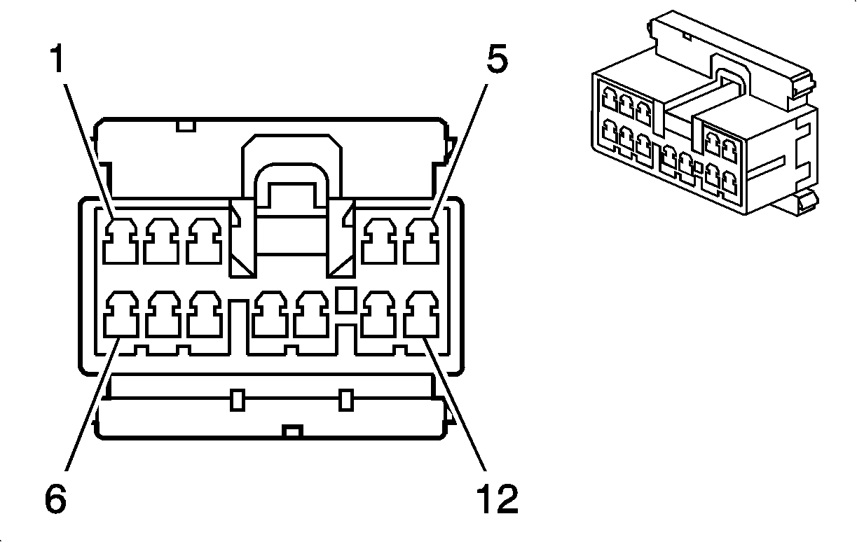
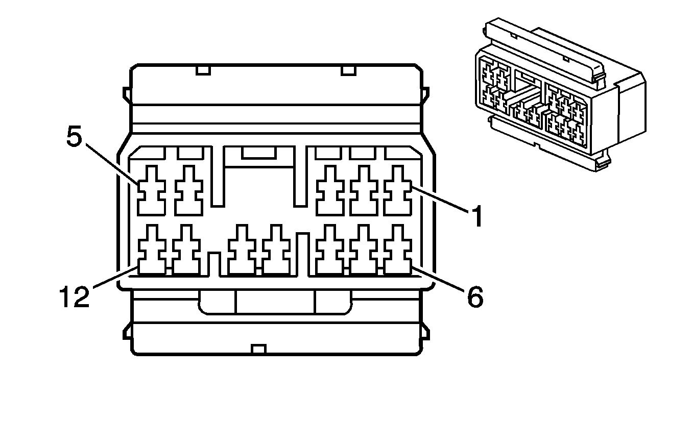
C240 I/P Harness to Front Floor Console Harness
|
|
Connector Part Information
| Connector Part Information
|
Terminal Part Information
| Terminal Part Information
|
Pin | Wire Color | Circuit No. | Function | Pin | Wire Color | Circuit No. | Function |
|---|---|---|---|---|---|---|---|
1 | GY | 8 | Instrument Panel Lamp Supply Voltage | 1 | GY | 8 | Instrument Panel Lamp Supply Voltage |
2 | -- | -- | Not Used | 2 | -- | -- | Not Used |
3 | WH | 1104 | Low Reference | 3 | WH | 1104 | Low Reference (UV6) |
4 | BN | 620 | HUD Image Down Control | 4 | BN | 620 | HUD Image Down Control (UV6) |
5 | YE | 621 | HUD Image Up Control | 5 | YE | 621 | HUD Image Up Control (UV6) |
6 | WH | 717 | Illuminated Display Signal | 6 | WH | 717 | Illuminated Display Signal (UV6) |
7 | BN | 622 | HUD Switch Signal | 7 | BN | 622 | HUD Switch Signal (UV6) |
8 | OG | 2540 | Battery Positive Voltage | 8 | OG | 2540 | Battery Positive Voltage |
9 | BN/WH | 1571 | Traction Control Switch Signal | 9 | BN/WH | 1571 | Traction Control Switch Signal |
10-11 | -- | -- | Not Used | 10-11 | -- | -- | Not Used |
12 | BK | 150 | Ground | 12 | BK | 150 | Ground |
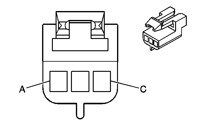
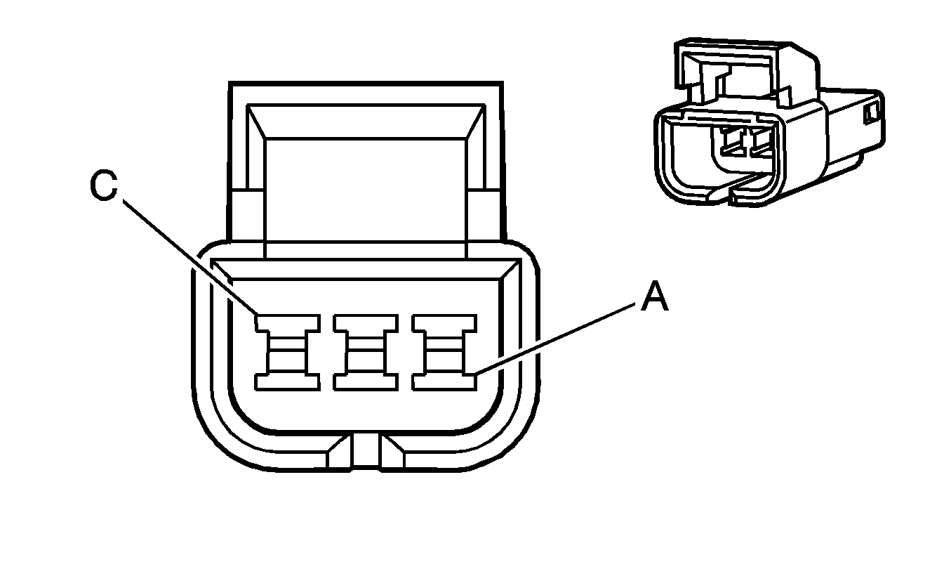
C241 I/P Harness to Shifter Harness
|
|
Connector Part Information
| Connector Part Information
|
Terminal Part Information
| Terminal Part Information
|
Pin | Wire Color | Circuit No. | Function | Pin | Wire Color | Circuit No. | Function |
|---|---|---|---|---|---|---|---|
A | GY | 8 | Instrument Panel Lamp Supply Voltage | A | GY | 8 | Instrument Panel Lamp Supply Voltage |
B | BK | 150 | Ground | B | BK | 150 | Ground |
C | D-GN/WH | 1135 | A/T Shift Lock Control Solenoid Supply Voltage | C | D-GN/WH | 1135 | A/T Shift Lock Control Solenoid Supply Voltage |
C250 I/P to Body Harness (Early Production)
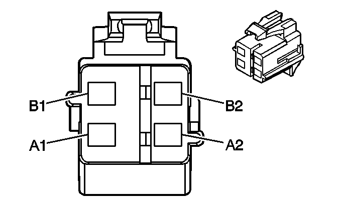
|
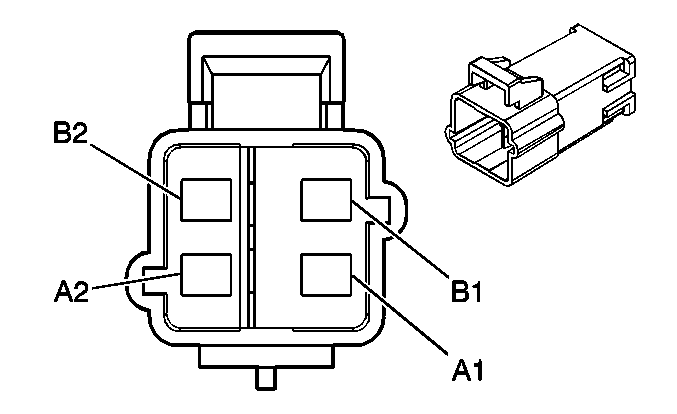
|
Connector Part Information
| Connector Part Information
|
Terminal Part Information
| Terminal Part Information
|
Pin | Wire Color | Circuit No. | Function | Pin | Wire Color | Circuit No. | Function |
|---|---|---|---|---|---|---|---|
A1 | TN | 3021 | Steering Wheel Module - Stage 1 - High Control | A1 | TN | 3021 | Steering Wheel Module - Stage 1 - High Control |
A2 | BN | 3020 | Steering Wheel Module - Stage 1 - Low Control | A2 | BN | 3020 | Steering Wheel Module - Stage 1 - Low Control |
B1 | WH | 3023 | Steering Wheel Module - Stage 2 - High Control | B1 | WH | 3023 | Steering Wheel Module - Stage 2 - High Control |
B2 | PK | 3022 | Steering Wheel Module - Stage 2 - Low Control | B2 | PK | 3022 | Steering Wheel Module - Stage 2 - Low Control |
C301 Body Harness to Left Front Door Harness
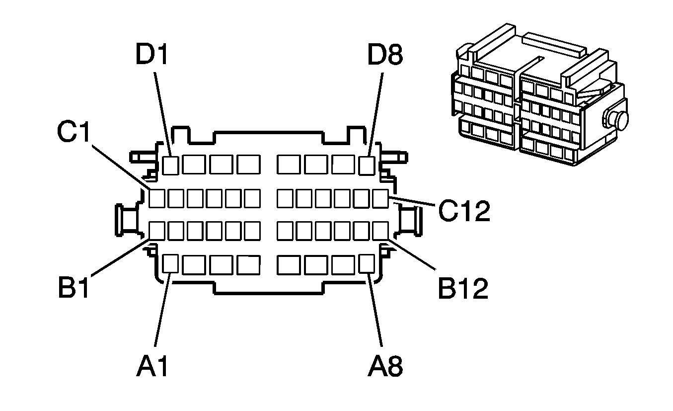
|
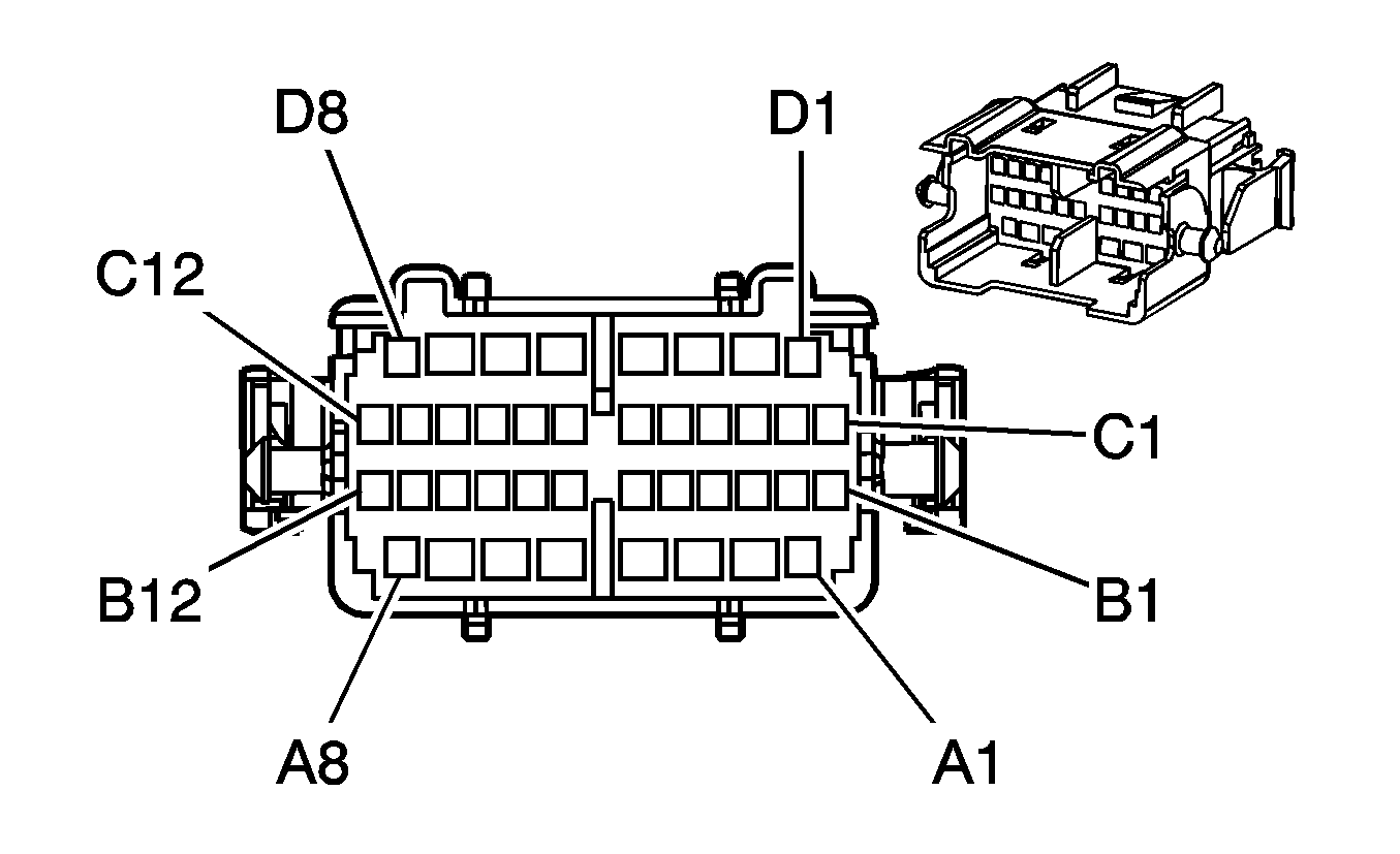
|
Connector Part Information
| Connector Part Information
|
Terminal Part Information
| Terminal Part Information
|
Pin | Wire Color | Circuit No. | Function | Pin | Wire Color | Circuit No. | Function |
|---|---|---|---|---|---|---|---|
A1 | GY | 295 | Door Lock Actuator Lock Control | A1 | GY | 295 | Door Lock Actuator Lock Control |
A2 | YE | 143 | Accessory Voltage | A2 | YE | 143 | Accessory Voltage |
A3 | L-BU | 166 | Power Window Master Switch Right Front Up Signal | A3 | L-BU | 166 | Power Window Master Switch Right Front Up Signal |
A4 | TN | 167 | Power Window Master Switch Right Front Down Signal | A4 | TN | 167 | Power Window Master Switch Right Front Down Signal |
A5 | L-GN | 170 | Power Window Master Switch Right Rear Up Signal | A5 | L-GN | 170 | Power Window Master Switch Right Rear Up Signal |
A6 | PU | 171 | Power Window Master Switch Right Rear Down Signal | A6 | PU | 171 | Power Window Master Switch Right Rear Down Signal |
A7 | D-GN | 168 | Power Window Master Switch Left Rear Up Signal | A7 | D-GN | 168 | Power Window Master Switch Left Rear Up Signal |
A8 | TN | 694 | Driver Door Lock Actuator Unlock Control | A8 | TN | 694 | Driver Door Lock Actuator Unlock Control |
B1 | GY | 118 | Left Front Speaker Output (-) (UW6) | B1 | YE | 1956 | Left Front Speaker Output (-) (UW6) |
B1 | YE | 1956 | Left Front Tweeter Speaker Output (-) (U87) | B1 | YE | 1956 | Left Front Tweeter Speaker Output (-) (U87) |
B2 | TN | 201 | Left Front Speaker Output (+) (UW6) | B2 | BK | 1856 | Left Front Speaker Output (+) (UW6) |
B2 | BK | 1856 | Left Front Tweeter Speaker Output (+) (U87) | B2 | BK | 1856 | Left Front Tweeter Speaker Output (+) (U87) |
B3 | GY | 118 | Left Front Speaker Output (-) | B3 | GY | 118 | Left Front Speaker Output (-) |
B4 | TN | 201 | Left Front Speaker Output (+) | B4 | TN | 201 | Left Front Speaker Output (+) |
B5 | BN/WH | 1498 | Passenger Mirror Motor Down Control | B5 | BN/WH | 1498 | Passenger Mirror Motor Down Control |
B6 | L-BU/WH | 1497 | Passenger Mirror Motor Left/Up Control | B6 | L-BU/WH | 1497 | Passenger Mirror Motor Left/Up Control |
B7 | RD/WH | 881 | Passenger Mirror Motor Right Control | B7 | RD/WH | 881 | Passenger Mirror Motor Right Control |
B8 | OG/BK | 781 | Driver Door Lock Switch Unlock Signal | B8 | OG/BK | 781 | Driver Door Lock Switch Unlock Signal |
B9 | RD/BK | 780 | Driver Door Lock Switch Lock Signal | B9 | RD/BK | 780 | Driver Door Lock Switch Lock Signal |
B10 | GY | 8 | Instrument Panel Lamp Supply Voltage | B10 | GY | 8 | Instrument Panel Lamp Supply Voltage |
B11 | GY/BK | 745 | Left Front Door Ajar Switch Signal | B11 | GY/BK | 745 | Left Front Door Ajar Switch Signal |
B12 | TN | 126 | Left Front Door Open Switch Signal | B12 | TN | 126 | Left Front Door Open Switch Signal |
C1 | L-GN | 1123 | Door Lock Key Switch Lock Signal | C1 | L-GN | 1123 | Door Lock Key Switch Lock Signal |
C2 | PU | 1124 | Door Lock Key Switch Unlock Signal | C2 | PU | 1124 | Door Lock Key Switch Unlock Signal |
C3 | OG | 840 | Battery Positive Voltage | C3 | OG | 840 | Battery Positive Voltage |
C4 | WH | 2132 | Side Impact Sensing Module - Left - Signal (AY1) | C4 | WH | 2132 | Side Impact Sensing Module - Left - Signal (AY1) |
C5 | YE | 2131 | Side Impact Sensing Module - Left - Voltage (AY1) | C5 | YE | 2131 | Side Impact Sensing Module - Left - Voltage (AY1) |
C6-C12 | -- | -- | Not Used | C6-C12 | -- | -- | Not Used |
D1 | -- | -- | Not Used | D1 | -- | -- | Not Used |
D2 | PU | 169 | Power Window Master Switch Left Rear Down Signal | D2 | PU | 169 | Power Window Master Switch Left Rear Down Signal |
D3 | D-BU | 1307 | Power Window Master Switch Lockout Control | D3 | D-BU | 1307 | Power Window Master Switch Lockout Control |
D4 | BK | 550 | Ground | D4 | BK | 550 | Ground |
D5-D8 | -- | -- | Not Used | D5-D8 | -- | -- | Not Used |
C302 I/P Harness to Right Front Door Harness

|

|
Connector Part Information
| Connector Part Information
|
Terminal Part Information
| Terminal Part Information
|
Pin | Wire Color | Circuit No. | Function | Pin | Wire Color | Circuit No. | Function |
|---|---|---|---|---|---|---|---|
A1 | GY | 295 | Door Lock Actuator Lock Control | A1 | GY | 295 | Door Lock Actuator Lock Control |
A2 | YE | 143 | Accessory Voltage | A2 | YE | 143 | Accessory Voltage |
A3 | L-BU | 166 | Power Window Master Switch Right Front Up Signal | A3 | L-BU | 166 | Power Window Master Switch Right Front Up Signal |
A4 | TN | 167 | Power Window Master Switch Right Front Down Signal | A4 | TN | 167 | Power Window Master Switch Right Front Down Signal |
A5-A7 | -- | -- | Not Used | A5-A7 | -- | -- | Not Used |
A8 | TN | 294 | Door Lock Actuator Unlock Control | A8 | TN | 294 | Door Lock Actuator Unlock Control |
B1 | BN/WH | 1498 | Passenger Mirror Motor Down Control | B1 | BN/WH | 1498 | Passenger Mirror Motor Down Control |
B2 | BK | 750 | Ground | B2 | BK | 750 | Ground |
B3 | RD/WH | 881 | Passenger Mirror Motor Right Control | B3 | RD/WH | 881 | Passenger Mirror Motor Right Control |
B4 | L-BU/WH | 1497 | Passenger Mirror Motor Left/Up Control | B4 | L-BU/WH | 1497 | Passenger Mirror Motor Left/Up Control |
B5 | D-GN | 117 | Right Front Speaker Output (-) (UW6) | B5 | PU | 1952 | Right Front Speaker Output (-) (UW6) |
B5 | PU | 1952 | Right Front Tweeter Speaker Output (-) (U87) | B5 | PU | 1952 | Right Front Tweeter Speaker Output (-) (U87) |
B6 | L-GN | 200 | Right Front Speaker Output (+) (UW6) | B6 | L-GN | 1852 | Right Front Speaker Output (+) (UW6) |
B6 | L-GN | 1852 | Right Front Tweeter Speaker Output (+) (U87) | B6 | L-GN | 1852 | Right Front Tweeter Speaker Output (+) (U87) |
B7 | D-GN | 117 | Right Front Speaker Output (-) | B7 | D-GN | 117 | Right Front Speaker Output (-) |
B8 | L-GN | 200 | Right Front Speaker Output (+) | B8 | L-GN | 200 | Right Front Speaker Output (+) |
B9 | L-GN | 1177 | Right Front Door Open Switch Signal | B9 | L-GN | 1177 | Right Front Door Open Switch Signal |
B10-B11 | -- | -- | Not Used | B10-B11 | -- | -- | Not Used |
B12 | L-BU | 244 | Passenger Door Lock Switch Lock Signal | B12 | L-BU | 244 | Passenger Door Lock Switch Lock Signal |
C1 | D-BU | 245 | Passenger Door Lock Switch Unlock Signal | C1 | D-BU | 245 | Passenger Door Lock Switch Unlock Signal |
C2 | GY | 8 | Instrument Panel Lamp Supply Voltage | C2 | GY | 8 | Instrument Panel Lamp Supply Voltage |
C3 | BK/WH | 746 | Right Front Door Ajar Switch Signal | C3 | BK/WH | 746 | Right Front Door Ajar Switch Signal |
C4 | D-GN | 2134 | Side Impact Sensing Module - Right - Signal (AY1) | C4 | D-GN | 2134 | Side Impact Sensing Module - Right - Signal (AY1) |
C5 | TN | 2133 | Side Impact Sensing Module - Right - Voltage (AY1) | C5 | TN | 2133 | Side Impact Sensing Module - Right - Voltage (AY1) |
C6-C12 | -- | -- | Not Used | C6-C12 | -- | -- | Not Used |
D1-D8 | -- | -- | Not Used | D1-D8 | -- | -- | Not Used |
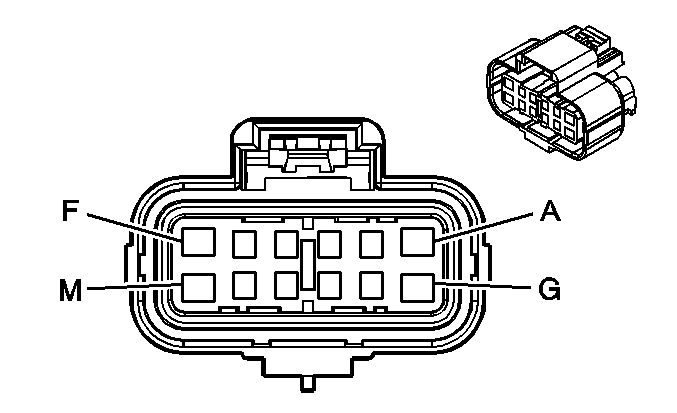
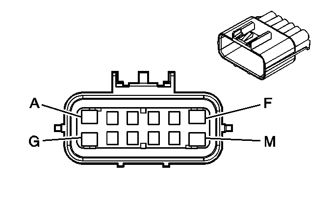
C311 Body Harness to Left Front Seat Harness
|
|
Connector Part Information
| Connector Part Information
|
Terminal Part Information
| Terminal Part Information
|
Pin | Wire Color | Circuit No. | Function | Pin | Wire Color | Circuit No. | Function |
|---|---|---|---|---|---|---|---|
A | OG | 1140 | Battery Positive Voltage | A | OG | 1140 | Battery Positive Voltage (AG1) |
B | YE | 2080 | Driver Heated Seat Cushion Temperature Sensor Low Reference (KA1) | B | YE | 2080 | Driver Heated Seat Cushion Temperature Sensor Low Reference (KA1) |
C | OG | 1440 | Battery Positive Voltage (KA1) | C | OG | 1440 | Battery Positive Voltage (KA1) |
D | PU | 2477 | Driver Heated Seat Relay Control (KA1) | D | PU | 2477 | Driver Heated Seat Relay Control (KA1) |
E | YE/BK | 2079 | Heated Seat Cushion Temperature Sensor Signal (KA1) | E | YE/BK | 2079 | Heated Seat Cushion Temperature Sensor Signal (KA1) |
F | -- | -- | Not Used | F | -- | -- | Not Used |
G | BK | 550 | Ground | G | BK | 550 | Ground |
H | BK/WH | 238 | Seat Belt Switch - Left | H | BK/WH | 238 | Seat Belt Switch - Left |
J-M | -- | -- | Not Used | J-M | -- | -- | Not Used |
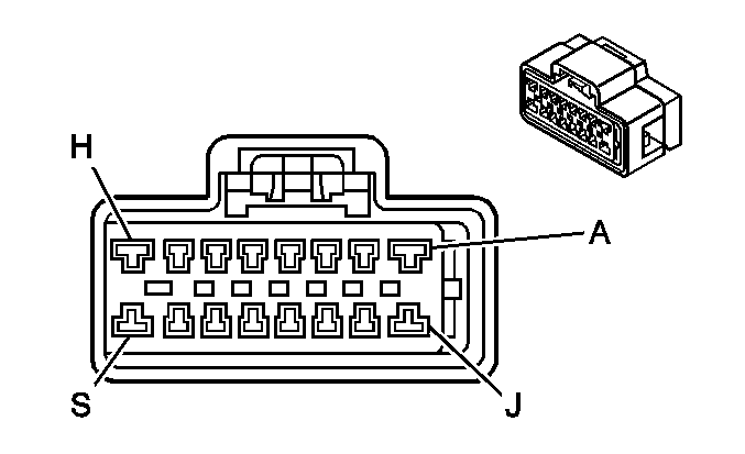
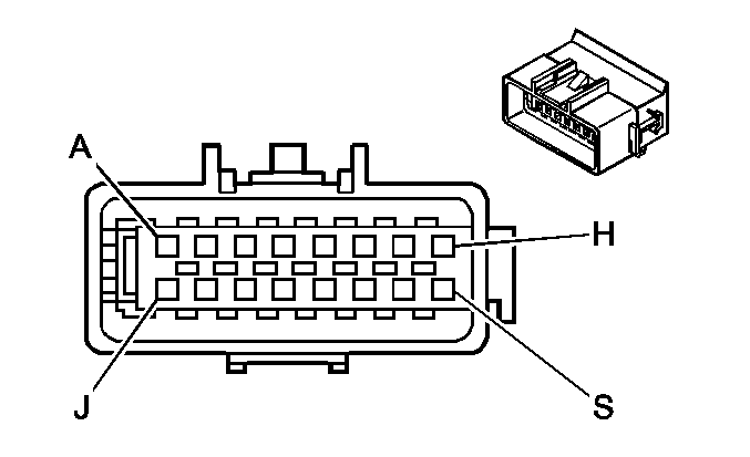
C313 Body Harness to Right Front Seat Harness
|
|
Connector Part Information
| Connector Part Information
|
Terminal Part Information
| Terminal Part Information
|
Pin | Wire Color | Circuit No. | Function | Pin | Wire Color | Circuit No. | Function |
|---|---|---|---|---|---|---|---|
A | BK | 750 | Ground | A | BK | 850 | Ground |
B | -- | -- | Not Used | B | -- | -- | Not Used |
C | GY | 2434 | Passenger Heated Seat Cushion Temperature Sensor Signal | C | GY | 2434 | Passenger Heated Seat Cushion Temperature Sensor Signal |
D | TN/WH | 2430 | Passenger Heated Seat Relay Control | D | TN/WH | 2430 | Passenger Heated Seat Relay Control |
E | RD | 1362 | Seat Belt Switch - Right | E | RD | 1362 | Seat Belt Switch - Right |
F | PK | 2435 | Passenger Heated Seat Cushion Temperature Sensor Low Reference | F | PK | 2435 | Passenger Heated Seat Cushion Temperature Sensor Low Reference |
G-J | -- | -- | Not Used | G-J | -- | -- | Not Used |
K | OG | 1440 | Battery Positive Voltage | K | OG | 1440 | Battery Positive Voltage |
L | BK/WH | 1751 | Ground | L | BK/WH | 1751 | Ground |
M | PK | 2306 | Occupant Sensor Serial Data Link | M | PK | 2306 | Occupant Sensor Serial Data Link |
N | D-BU | 2307 | Passenger Air Bag On Indicator Control | N | D-BU | 2307 | Passenger Air Bag On Indicator Control |
P | D-GN | 2308 | Passenger Air Bag Off Indicator Control | P | D-GN | 2308 | Passenger Air Bag Off Indicator Control |
R | OG | 640 | Battery Positive Voltage | R | OG | 640 | Battery Positive Voltage |
S | YE | 1139 | Ignition 1 Voltage | S | YE | 1139 | Ignition 1 Voltage |
C315 Right Front Seat Safety Harness to Body Harness
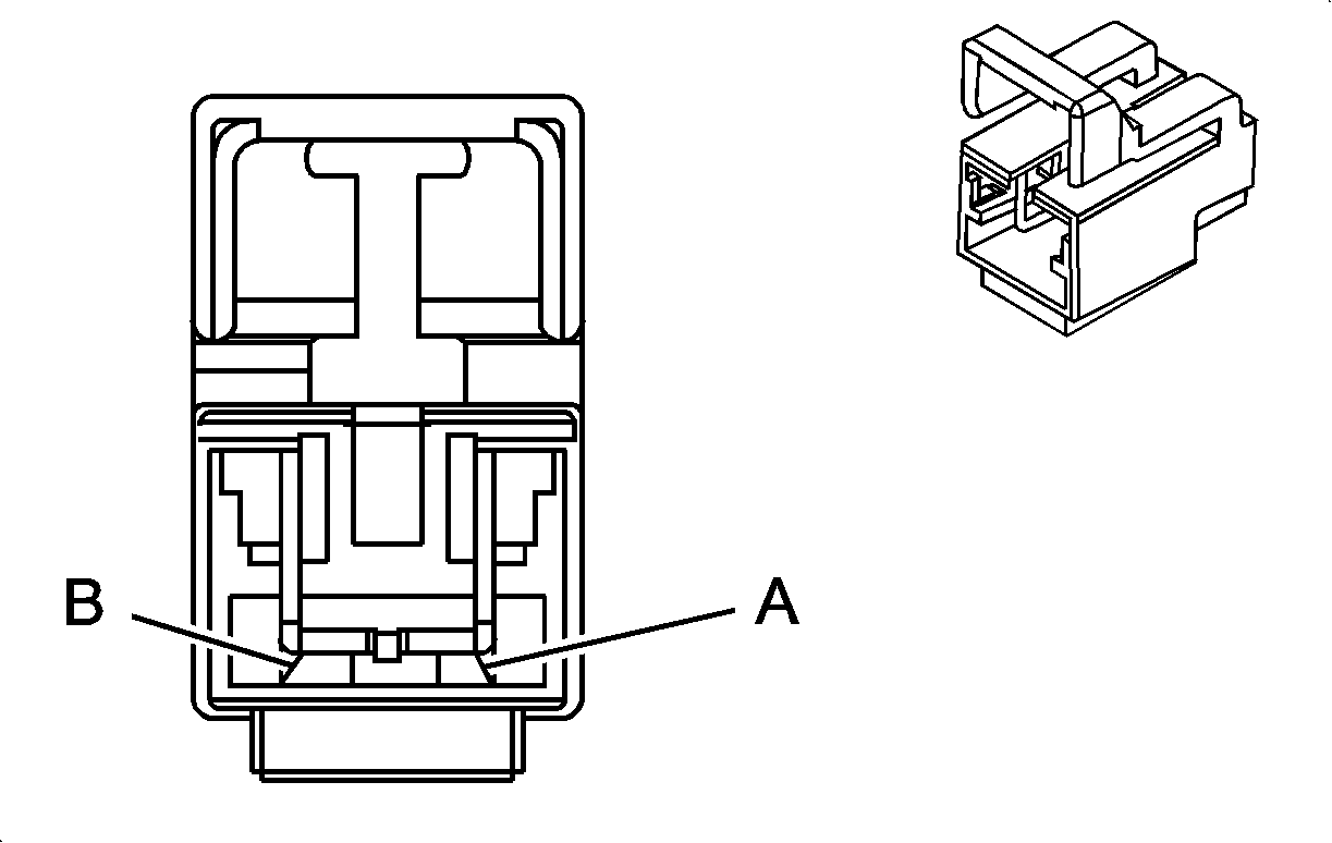
|
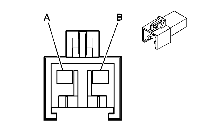
|
Connector Part Information
| Connector Part Information
|
Terminal Part Information
| Terminal Part Information
|
Pin | Wire Color | Circuit No. | Function | Pin | Wire Color | Circuit No. | Function |
|---|---|---|---|---|---|---|---|
A | L-GN | 2116 | Seat Belt Pretensioner - Right - High Control | A | L-GN | 2116 | Seat Belt Pretensioner - Right - High Control |
B | OG | 2117 | Seat Belt Pretensioner - Right - Low Control | B | OG | 2117 | Seat Belt Pretensioner - Right - Low Control |
C316 Left Front Seat Safety Harness to Body Harness

|

|
Connector Part Information
| Connector Part Information
|
Terminal Part Information
| Terminal Part Information
|
Pin | Wire Color | Circuit No. | Function | Pin | Wire Color | Circuit No. | Function |
|---|---|---|---|---|---|---|---|
A | BK/WH | 2118 | Seat Belt Pretensioner - Left - High Control | A | BK/WH | 2118 | Seat Belt Pretensioner - Left - High Control |
B | OG/BK | 2119 | Seat Belt Pretensioner - Left - Low Control | B | OG/BK | 2119 | Seat Belt Pretensioner - Left - Low Control |
C355 Body Harness to Left Rear Door Harness
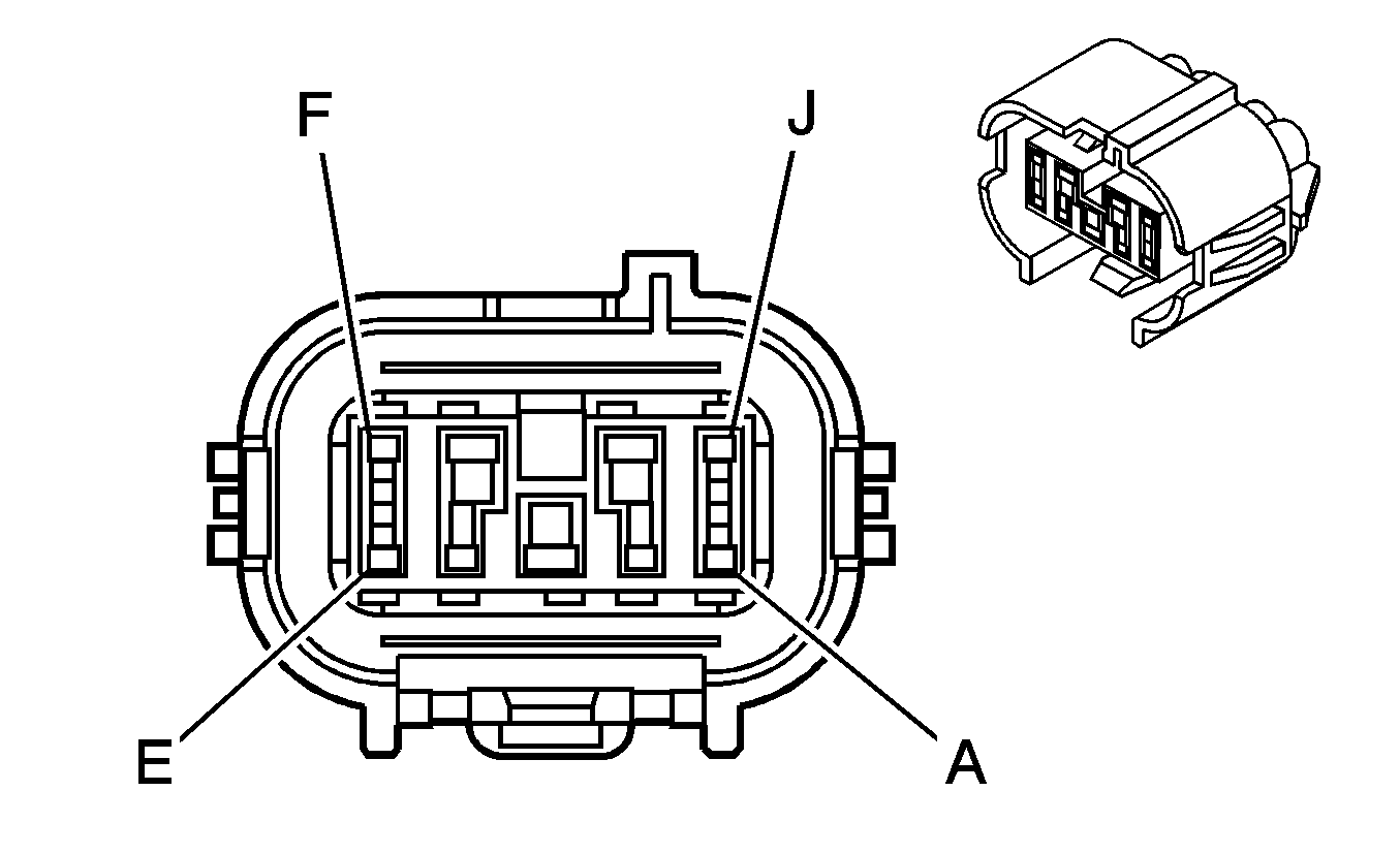
|
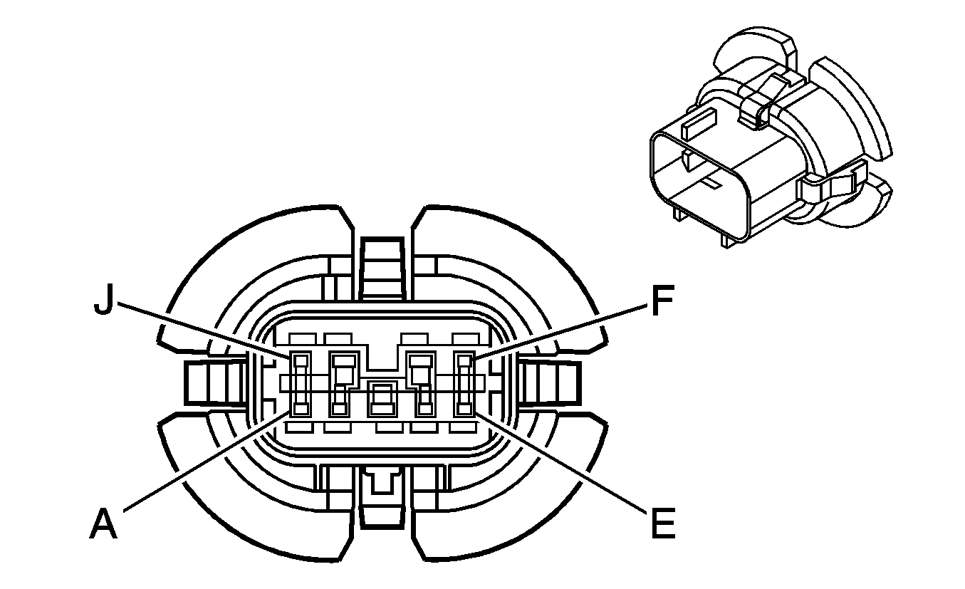
|
Connector Part Information
| Connector Part Information
|
Terminal Part Information
| Terminal Part Information
|
Pin | Wire Color | Circuit No. | Function | Pin | Wire Color | Circuit No. | Function |
|---|---|---|---|---|---|---|---|
A | BK | 550 | Ground | A | BK | 550 | Ground |
B | TN | 294 | Door Lock Actuator Unlock Control | B | TN | 294 | Door Lock Actuator Unlock Control |
C | D-BU | 1307 | Power Window Master Switch Lockout Control | C | D-BU | 1307 | Power Window Master Switch Lockout Control |
D | D-BU/WH | 1179 | Left Rear Door Open Switch Signal | D | D-BU/WH | 1179 | Left Rear Door Open Switch Signal |
E | GY | 295 | Door Lock Actuator Lock Control | E | GY | 295 | Door Lock Actuator Lock Control |
F | L-BU/BK | 747 | Left Rear Door Ajar Switch Signal | F | L-BU/BK | 747 | Left Rear Door Ajar Switch Signal |
G | D-GN | 168 | Power Window Master Switch Left Rear Up Signal | G | D-GN | 168 | Power Window Master Switch Left Rear Up Signal |
H | PU | 169 | Power Window Master Switch Left Rear Down Signal | H | PU | 169 | Power Window Master Switch Left Rear Down Signal |
J | -- | -- | Not Used | J | -- | -- | Not Used |
C356 Body Harness to Right Rear Door Harness

|

|
Connector Part Information
| Connector Part Information
|
Terminal Part Information
| Terminal Part Information
|
Pin | Wire Color | Circuit No. | Function | Pin | Wire Color | Circuit No. | Function |
|---|---|---|---|---|---|---|---|
A | BK | 750 | Ground | A | BK | 750 | Ground |
B | TN | 294 | Door Lock Actuator Unlock Control | B | TN | 294 | Door Lock Actuator Unlock Control |
C | D-BU | 1307 | Power Window Master Switch Lockout Control | C | D-BU | 1307 | Power Window Master Switch Lockout Control |
D | YE/BK | 1181 | Right Rear Door Open Switch Signal | D | YE/BK | 1181 | Right Rear Door Open Switch Signal |
E | GY | 295 | Door Lock Actuator Lock Control | E | GY | 295 | Door Lock Actuator Lock Control |
F | L-GN/BK | 748 | Right Rear Door Ajar Switch Signal | F | L-GN/BK | 748 | Right Rear Door Ajar Switch Signal |
G | L-GN | 170 | Power Window Master Switch Right Rear Up Signal | G | L-GN | 170 | Power Window Master Switch Right Rear Up Signal |
H | PU | 171 | Power Window Master Switch Right Rear Down Signal | H | PU | 171 | Power Window Master Switch Right Rear Down Signal |
J | -- | -- | Not Used | J | -- | -- | Not Used |
C390 Roof Harness to Body Harness

|

|
Connector Part Information
| Connector Part Information
|
Terminal Part Information
| Terminal Part Information
|
Pin | Wire Color | Circuit No. | Function | Pin | Wire Color | Circuit No. | Function |
|---|---|---|---|---|---|---|---|
A | OG | 1732 | Inadvertent Power Courtesy Lamp (TR9, CF5) | A | OG | 1732 | Inadvertent Power Courtesy Lamp |
B | BK | 750 | Ground | B | BK | 750 | Ground |
C | YE | 643 | Accessory Voltage (CF5) | C | YE | 643 | Accessory Voltage |
D | -- | -- | Not Used | D | -- | -- | Not Used |
E | GY | 655 | Cellular Microphone Signal (UE1) | E | GY | 655 | Cellular Microphone Signal |
F | BARE | 1705 | Drain Wire (UE1) | F | BARE | 1705 | Drain Wire |
G | GY/BK | 690 | Courtesy Lamp Supply Voltage | G | GY/BK | 690 | Courtesy Lamp Supply Voltage |
H | D-GN/WH | 2514 | Keypad Signal (UE1) | H | D-GN/WH | 2514 | Keypad Signal |
J | L-GN/BK | 2515 | Keypad Supply Voltage (UE1) | J | L-GN/BK | 2515 | Keypad Supply Voltage |
K | YE/BK | 2516 | Keypad Green LED Signal (UE1) | K | YE/BK | 2516 | Keypad Green LED Signal |
L | BN/WH | 2517 | Keypad Red LED Signal (UE1) | L | BN/WH | 2517 | Keypad Red LED Signal |
M | -- | -- | Not Used | M | -- | -- | Not Used |
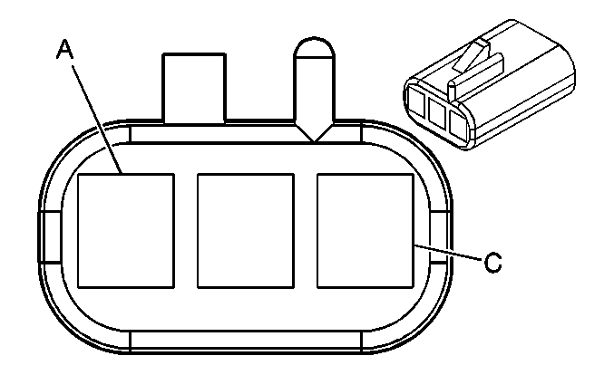
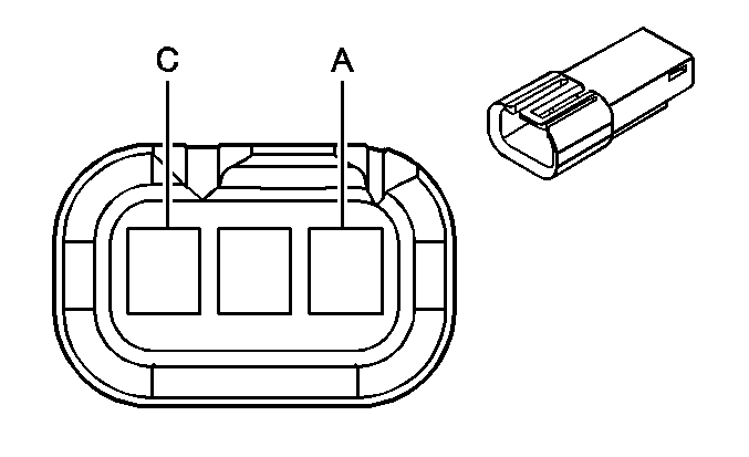
C391 Roof Harness to Rail Lamp Jumper Harness (w/oTR9/CF5)
|
|
Connector Part Information
| Connector Part Information
|
Terminal Part Information
| Terminal Part Information
|
Pin | Wire Color | Circuit No. | Function | Pin | Wire Color | Circuit No. | Function |
|---|---|---|---|---|---|---|---|
A | -- | -- | Not Used | A | -- | -- | Not Used |
B | BK | 750 | Ground | B | BK | 750 | Ground |
C | GY | 690 | Courtesy Lamp Supply Voltage | C | GY | 690 | Courtesy Lamp Supply Voltage |
C392 Roof Harness to Rail Lamp Jumper Harness (w/oTR9/CF5)

|

|
Connector Part Information
| Connector Part Information
|
Terminal Part Information
| Terminal Part Information
|
Pin | Wire Color | Circuit No. | Function | Pin | Wire Color | Circuit No. | Function |
|---|---|---|---|---|---|---|---|
A | -- | -- | Not Used | A | -- | -- | Not Used |
B | BK | 750 | Ground | B | BK | 750 | Ground |
C | GY | 690 | Courtesy Lamp Supply Voltage | C | GY | 690 | Courtesy Lamp Supply Voltage |
C398 (CF5) Roof Harness to Sunroof Harness

|

|
Connector Part Information
| Connector Part Information
|
Terminal Part Information
| Terminal Part Information
|
Pin | Wire Color | Circuit No. | Function | Pin | Wire Color | Circuit No. | Function |
|---|---|---|---|---|---|---|---|
1 | BN | 100 | Sunroof Switch Open Signal | 1 | BN | 100 | Sunroof Switch Open Signal |
2 | OG | 110 | Sunroof Switch Close Signal | 2 | OG | 110 | Sunroof Switch Close Signal |
3 | BU | 128 | Sunroof Switch Low Reference | 3 | D-BU | 128 | Sunroof Switch Low Reference |
4 | BK | 750 | Ground | 4 | BK | 750 | Ground |
5 | YE | 643 | Accessory Voltage | 5 | YE | 643 | Accessory Voltage |
6 | -- | -- | Not Used | 6 | -- | -- | Not Used |
C399 Roof Harness to Overhead Console Harness (TR9) or Roof Rail Jumper Harness (CF5)

|

|
Connector Part Information
| Connector Part Information
|
Terminal Part Information
| Terminal Part Information
|
Pin | Wire Color | Circuit No. | Function | Pin | Wire Color | Circuit No. | Function |
|---|---|---|---|---|---|---|---|
A | OG | 1732 | Inadvertent Power Courtesy Lamp | A | OG | 1732 | Inadvertent Power Courtesy Lamp |
B | BK | 750 | Ground | B | BK | 750 | Ground |
C | GY | 690 | Courtesy Lamp Supply Voltage | C | GY | 690 | Courtesy Lamp Supply Voltage |
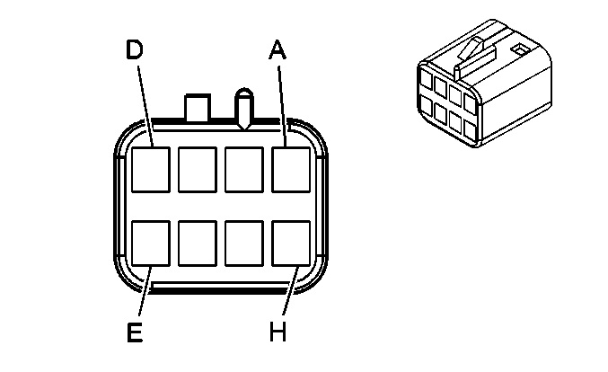
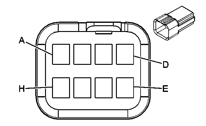
C400 Rear Deck Lid Harness to Body Harness
|
|
Connector Part Information
| Connector Part Information
|
Terminal Part Information
| Terminal Part Information
|
Pin | Wire Color | Circuit No. | Function | Pin | Wire Color | Circuit No. | Function |
|---|---|---|---|---|---|---|---|
A | BN | 9 | Park Lamp Supply Voltage | A | BN | 9 | Park Lamp Supply Voltage |
B | WH | 17 | Stop Lamp Switch Signal | B | WH | 17 | Stop Lamp Switch Signal |
C | L-GN | 24 | Backup Lamp Supply Voltage | C | L-GN | 24 | Backup Lamp Supply Voltage |
D | OG/BK | 737 | Rear Compartment Lamp Control | D | OG/BK | 737 | Rear Compartment Lamp Control |
E | BK | 750 | Ground | E | BK | 750 | Ground |
F | L-BU | 1344 | Trunk Release Control | F | L-BU | 1344 | Trunk Release Control |
G | -- | -- | Not Used | G | -- | -- | Not Used |
H | RD/BK | 744 | Rear Compartment Lid Ajar Switch Signal | H | RD/BK | 744 | Rear Compartment Lid Ajar Switch Signal |
C401 Body Harness to Left Rear Lamp Harness
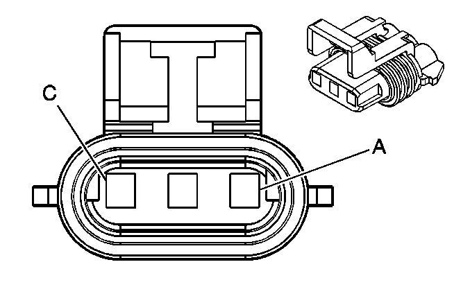
|
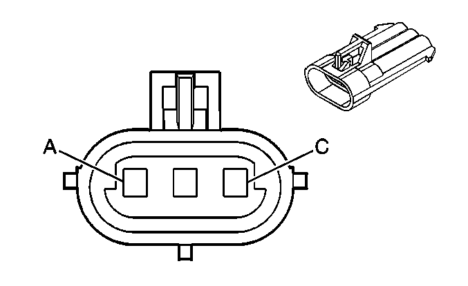
|
Connector Part Information
| Connector Part Information
|
Terminal Part Information
| Terminal Part Information
|
Pin | Wire Color | Circuit No. | Function | Pin | Wire Color | Circuit No. | Function |
|---|---|---|---|---|---|---|---|
A | YE | 18 | Left Rear Stop/Turn Lamp Supply Voltage | A | YE | 18 | Left Rear Stop/Turn Lamp Supply Voltage |
B | BN | 9 | Park Lamp Supply Voltage | B | BN | 9 | Park Lamp Supply Voltage |
C | BK | 550 | Ground | C | BK | 550 | Ground |
C402 Body Harness to Right Rear Lamp Harness

|

|
Connector Part Information
| Connector Part Information
|
Terminal Part Information
| Terminal Part Information
|
Pin | Wire Color | Circuit No. | Function | Pin | Wire Color | Circuit No. | Function |
|---|---|---|---|---|---|---|---|
A | D-GN | 19 | Right Rear Stop/Turn Lamp Supply Voltage | A | YE | 19 | Right Rear Stop/Turn Lamp Supply Voltage |
B | BN | 9 | Park Lamp Supply Voltage | B | BN | 9 | Park Lamp Supply Voltage |
C | BK | 750 | Ground | C | BK | 750 | Ground |
C403 Rear Applique Harness to Rear Deck Lid Harness
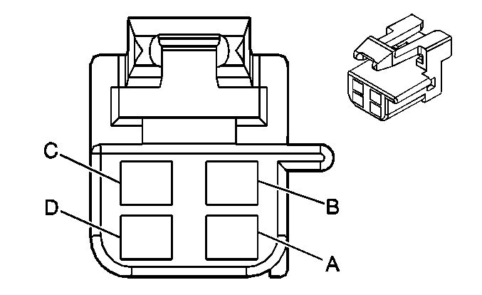
|
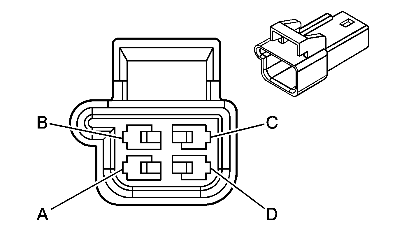
|
Connector Part Information
| Connector Part Information
|
Terminal Part Information
| Terminal Part Information
|
Pin | Wire Color | Circuit No. | Function | Pin | Wire Color | Circuit No. | Function |
|---|---|---|---|---|---|---|---|
A | BN | 9 | Park Lamp Supply Voltage | A | BN | 9 | Park Lamp Supply Voltage |
B | D-GN | 24 | Backup Lamp Supply Voltage | B | L-GN | 24 | Backup Lamp Supply Voltage |
C | BK | 750 | Ground | C | BK | 750 | Ground |
D | -- | -- | Not Used | D | -- | -- | Not Used |
C404 CHMSL Jumper Harness to Rear Deck Lid Harness

|

|
Connector Part Information
| Connector Part Information
|
Terminal Part Information
| Terminal Part Information
|
Pin | Wire Color | Circuit No. | Function | Pin | Wire Color | Circuit No. | Function |
|---|---|---|---|---|---|---|---|
A | WH | 17 | Stop Lamp Switch Signal | A | WH | 17 | Stop Lamp Switch Signal |
B | -- | -- | Not Used | B | -- | -- | Not Used |
C | BK | 750 | Ground | C | BK | 750 | Ground |
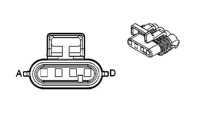
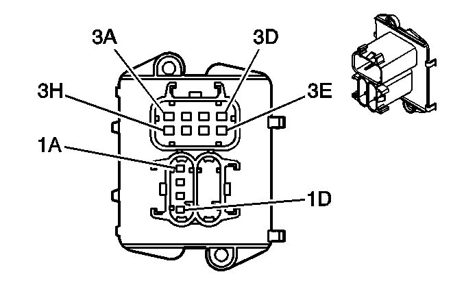
C405 Wheel Speed Harness/Fuel Tank Harness to Body Harness
|
|
Connector Part Information
| Connector Part Information
|
Terminal Part Information
| Terminal Part Information
|
Pin | Wire Color | Circuit No. | Function | Pin | Wire Color | Circuit No. | Function |
|---|---|---|---|---|---|---|---|
A | BN | 882 | Right Rear Wheel Speed Sensor Signal (JL9) | 1A | BN | 882 | Right Rear Wheel Speed Sensor Signal (JL9) |
B | WH | 883 | Right Rear Wheel Speed Sensor Low Reference (JL9) | 1B | WH | 883 | Right Rear Wheel Speed Sensor Low Reference (JL9) |
C | BK | 884 | Left Rear Wheel Speed Sensor Signal (JL9) | 1C | BK | 884 | Left Rear Wheel Speed Sensor Signal (JL9) |
D | RD | 885 | Left Rear Wheel Speed Sensor Low Reference (JL9) | 1D | RD | 885 | Left Rear Wheel Speed Sensor Low Reference (JL9) |
A | BK | 1850 | Ground | 3A | BK | 1850 | Ground |
B | OG/BK | 510 | Low Reference | 3B | BK | 2759 | Low Reference |
C | GY | 120 | Fuel Pump Supply Voltage | 3C | GY | 120 | Fuel Pump Supply Voltage |
D | PU | 30 | Fuel Level Sensor Signal | 3D | PU/WH | 1589 | Fuel Level Sensor Signal |
E | -- | -- | Not Used | 3E | -- | -- | Not Used |
F | GY/BK | 416 | 5-Volt Reference 1 | 3F | GY | 2709 | 5-Volt Reference 1 |
G | D-GN | 890 | Fuel Tank Pressure Sensor Signal | 3G | D-GN | 890 | Fuel Tank Pressure Sensor Signal |
H | OG/BK | 469 | Low Reference | 3H | BK | 2759 | Low Reference |
H | OG/BK | 469 | Low Reference | 3H | BK | 2759 | Low Reference |
C501 Left Front Door Harness to Left Front Door Trim Harness

|

|
Connector Part Information
| Connector Part Information
|
Terminal Part Information
| Terminal Part Information
|
Pin | Wire Color | Circuit No. | Function | Pin | Wire Color | Circuit No. | Function |
|---|---|---|---|---|---|---|---|
A1 | -- | -- | Not Used | A1 | -- | -- | Not Used |
A2 | YE | 143 | Accessory Voltage | A2 | YE | 143 | Accessory Voltage |
A3 | L-BU | 166 | Power Window Master Switch Right Front Up Signal | A3 | L-BU | 166 | Power Window Master Switch Right Front Up Signal |
A4 | TN | 167 | Power Window Master Switch Right Front Down Signal | A4 | TN | 167 | Power Window Master Switch Right Front Down Signal |
A5 | L-GN | 170 | Power Window Master Switch Right Rear Up Signal | A5 | L-GN | 170 | Power Window Master Switch Right Rear Up Signal |
A6 | PU | 171 | Power Window Master Switch Right Rear Down Signal | A6 | PU | 171 | Power Window Master Switch Right Rear Down Signal |
A7 | D-GN | 168 | Power Window Master Switch Left Rear Up Signal | A7 | D-GN | 168 | Power Window Master Switch Left Rear Up Signal |
A8 | -- | -- | Not Used | A8 | -- | -- | Not Used |
B1 | YE | 1956 | Left Front Speaker Output (-) (UW6) | B1 | YE | 1956 | Left Front Speaker Output (-) (UW6) |
B1 | YE | 1956 | Left Front Tweeter Speaker Output (-) (U87) | B1 | YE | 1956 | Left Front Tweeter Speaker Output (-) (U87) |
B2 | BK | 1856 | Left Front Speaker Output (+) (UW6) | B2 | BK | 1856 | Left Front Speaker Output (+) (UW6) |
B2 | BK | 1856 | Left Front Tweeter Speaker Output (+) (U87) | B2 | BK | 1856 | Left Front Tweeter Speaker Output (+) (U87) |
B3-B4 | -- | -- | Not Used | B3-B4 | -- | -- | Not Used |
B5 | BN/WH | 1498 | Passenger Mirror Motor Down Control | B5 | BN/WH | 1498 | Passenger Mirror Motor Down Control |
B6 | L-BU/WH | 1497 | Passenger Mirror Motor Left/Up Control | B6 | L-BU/WH | 1497 | Passenger Mirror Motor Left/Up Control |
B7 | RD/WH | 881 | Passenger Mirror Motor Right Control | B7 | RD/WH | 881 | Passenger Mirror Motor Right Control |
B8 | OG/BK | 781 | Driver Door Lock Switch Unlock Signal | B8 | OG/BK | 781 | Driver Door Lock Switch Unlock Signal |
B9 | RD/BK | 780 | Driver Door Lock Switch Lock Signal | B9 | RD/BK | 780 | Driver Door Lock Switch Lock Signal |
B10 | GY | 8 | Instrument Panel Lamp Supply Voltage | B10 | GY | 8 | Instrument Panel Lamp Supply Voltage |
B11-B12 | -- | -- | Not Used | B11-B12 | -- | -- | Not Used |
C1 | WH | 81 | Driver Mirror Motor Right Control | C1 | WH | 81 | Driver Mirror Motor Right Control |
C2 | YE | 88 | Driver Mirror Motor Down Control | C2 | YE | 88 | Driver Mirror Motor Down Control |
C3 | OG | 840 | Battery Positive Voltage | C3 | OG | 840 | Battery Positive Voltage |
C4 | L-GN | 1499 | Driver Mirror Motor Left/Up Control | C4 | L-GN | 1499 | Driver Mirror Motor Left/Up Control |
C5-C12 | -- | -- | Not Used | C5-C12 | -- | -- | Not Used |
D1 | -- | -- | Not Used | D1 | -- | -- | Not Used |
D2 | PU | 169 | Power Window Master Switch Left Rear Down Signal | D2 | PU | 169 | Power Window Master Switch Left Rear Down Signal |
D3 | D-BU | 1307 | Power Window Master Switch Lockout Control | D3 | D-BU | 1307 | Power Window Master Switch Lockout Control |
D4 | BK | 550 | Ground | D4 | BK | 550 | Ground |
D5 | BN | 165 | Power Window Motor Left Front Down Control | D5 | BN | 165 | Power Window Motor Left Front Down Control |
D6 | D-BU | 164 | Power Window Motor Left Front Up Control | D6 | D-BU | 164 | Power Window Motor Left Front Up Control |
D7-D8 | -- | -- | Not Used | D7-D8 | -- | -- | Not Used |
C601 Right Front Door Harness to Right Front Door Trim Harness

|

|
Connector Part Information
| Connector Part Information
|
Terminal Part Information
| Terminal Part Information
|
Pin | Wire Color | Circuit No. | Function | Pin | Wire Color | Circuit No. | Function |
|---|---|---|---|---|---|---|---|
A1 | -- | -- | Not Used | A1 | -- | -- | Not Used |
A2 | YE | 143 | Accessory Voltage | A2 | YE | 143 | Accessory Voltage |
A3 | L-BU | 166 | Power Window Master Switch Right Front Up Signal | A3 | L-BU | 166 | Power Window Master Switch Right Front Up Signal |
A4 | TN | 167 | Power Window Master Switch Right Front Down Signal | A4 | TN | 167 | Power Window Master Switch Right Front Down Signal |
A5 | D-BU | 666 | Power Window Motor Right Front Up Control | A5 | D-BU | 666 | Power Window Motor Right Front Up Control |
A6 | BN | 667 | Power Window Motor Right Front Down Control | A6 | BN | 667 | Power Window Motor Right Front Down Control |
A7-A8 | -- | -- | Not Used | A7-A8 | -- | -- | Not Used |
B1 | -- | -- | Not Used | B1 | -- | -- | Not Used |
B2 | BK | 750 | Ground | B2 | BK | 750 | Ground |
B3-B4 | -- | -- | Not Used | B3-B4 | -- | -- | Not Used |
B5 | PU | 1952 | Right Front Speaker Output (-) (UW6) | B5 | PU | 1952 | Right Front Speaker Output (-) (UW6) |
B5 | PU | 1952 | Right Front Tweeter Speaker Output (-) (U87) | B5 | PU | 1952 | Right Front Tweeter Speaker Output (-) (U87) |
B6 | L-GN | 1852 | Right Front Speaker Output (+) (UW6) | B6 | L-GN | 1852 | Right Front Speaker Output (+) (UW6) |
B6 | L-GN | 1852 | Right Front Tweeter Speaker Output (+) (U87) | B6 | L-GN | 1852 | Right Front Tweeter Speaker Output (+) (U87) |
B7-B11 | -- | -- | Not Used | B7-B11 | -- | -- | Not Used |
B12 | L-BU | 244 | Passenger Door Lock Switch Lock Signal | B12 | L-BU | 244 | Passenger Door Lock Switch Lock Signal |
C1 | D-BU | 245 | Passenger Door Lock Switch Unlock Signal | C1 | D-BU | 245 | Passenger Door Lock Switch Unlock Signal |
C2 | GY | 8 | Instrument Panel Lamp Supply Voltage | C2 | GY | 8 | Instrument Panel Lamp Supply Voltage |
C3-C12 | -- | -- | Not Used | C3-C12 | -- | -- | Not Used |
D1-D8 | -- | -- | Not Used | D1-D8 | -- | -- | Not Used |
