For 1990-2009 cars only
Special Tools
| • | J 8433 Two Jaw Puller |
| • | J 41816-2 Crankshaft End Protector |
| • | J 41558 Crankshaft Sprocket Remover |
| • | J 41665 Crankshaft Balancer and Sprocket Installer |
Removal Procedure
- Remove the oil pump. Refer to Oil Pump, Screen, and Crankshaft Oil Deflector Replacement .
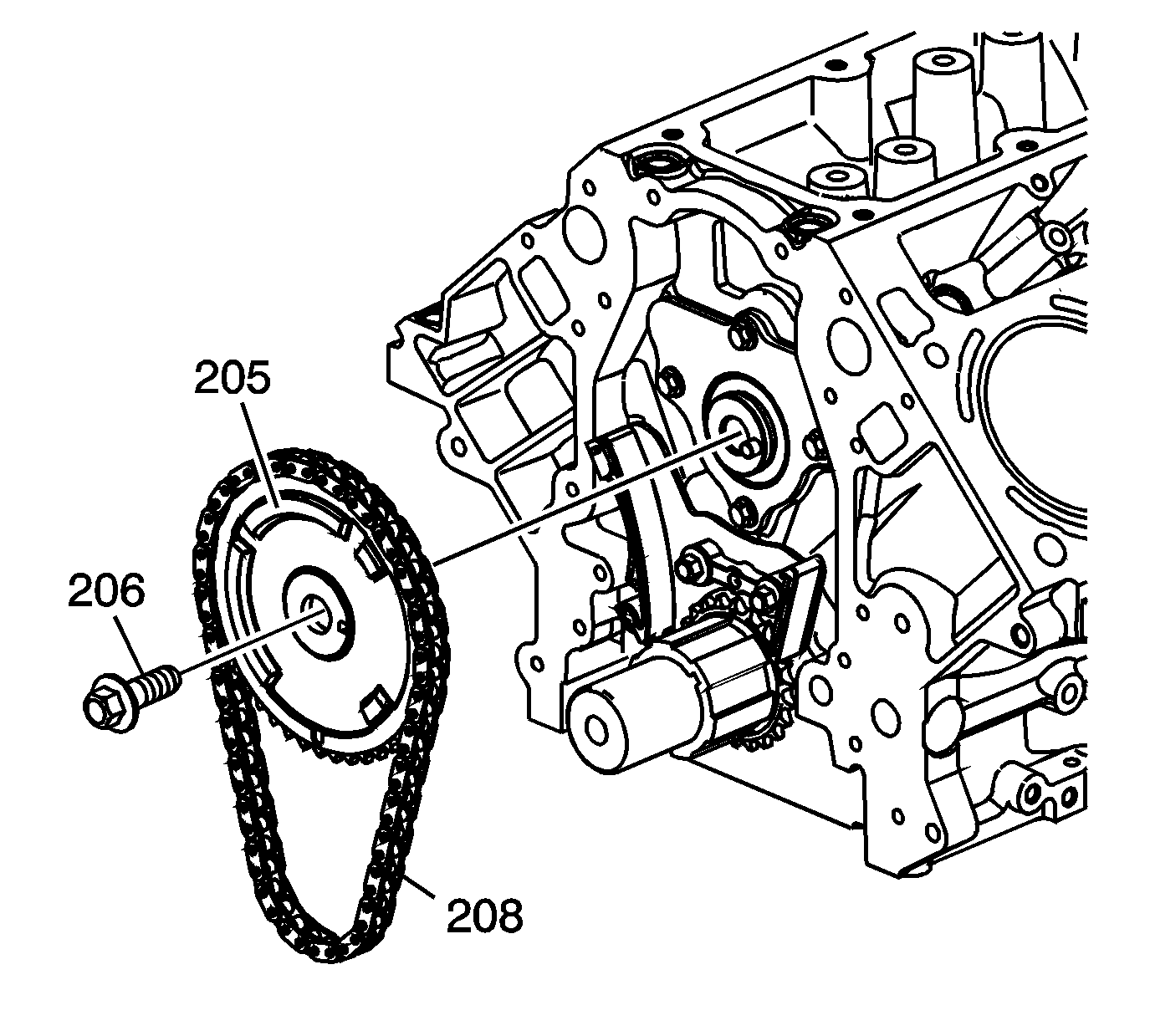
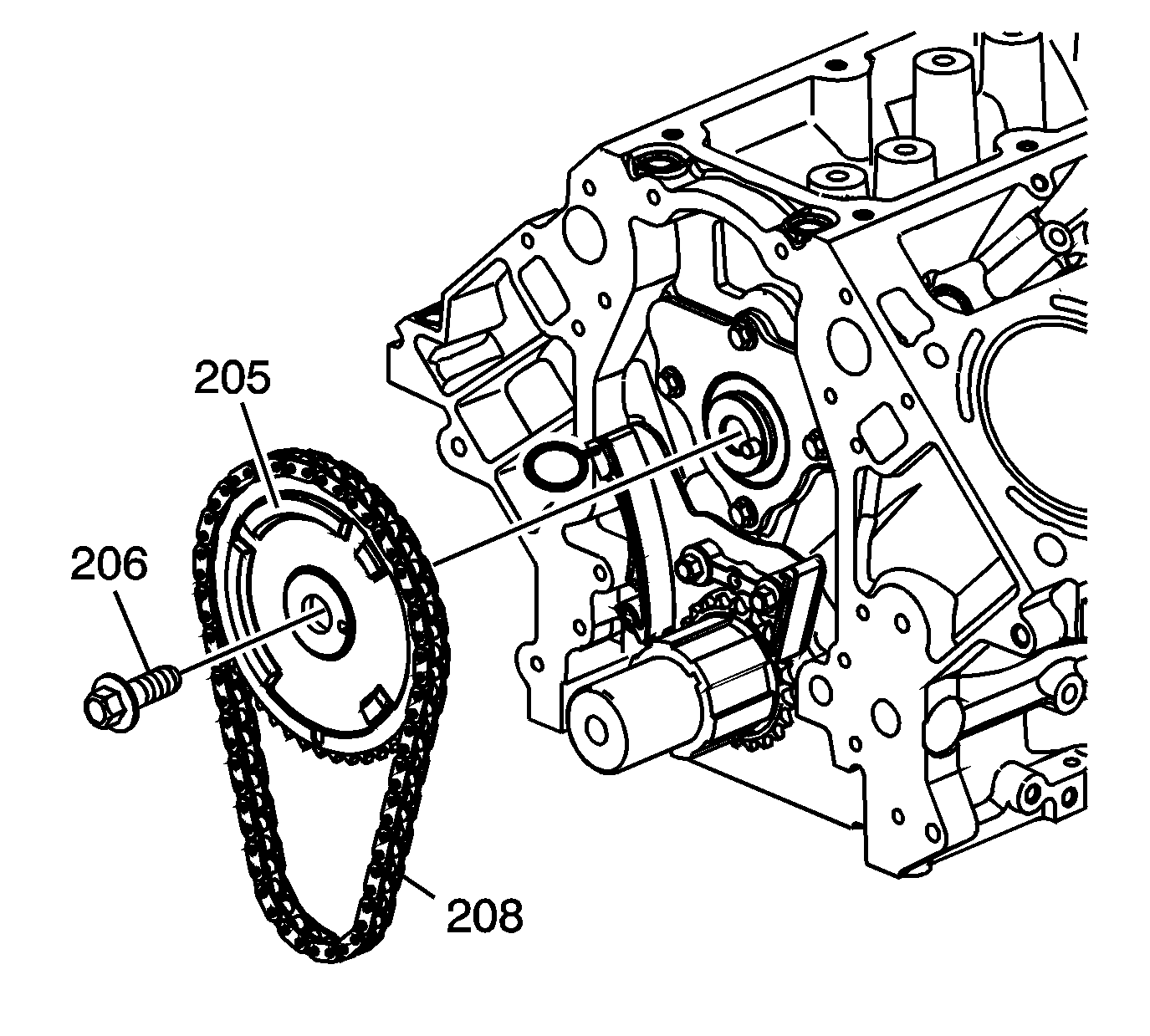
- Remove and discard the camshaft sprocket bolt (206).
- Remove the camshaft sprocket (205) and timing chain (208).
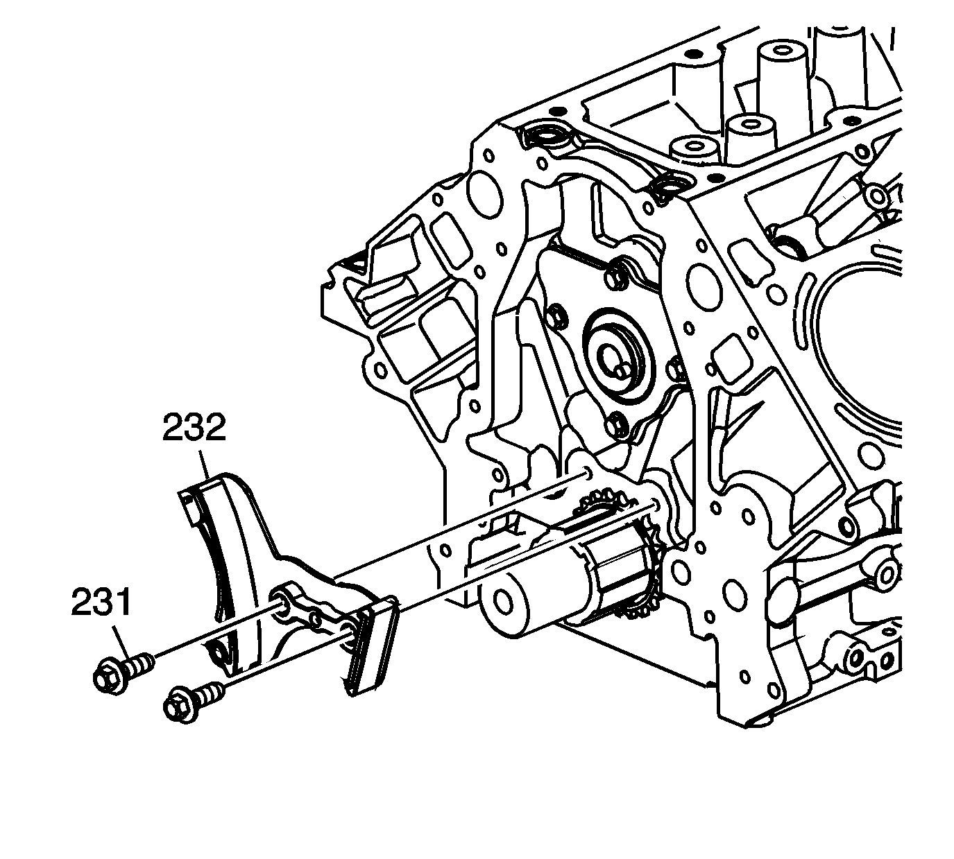
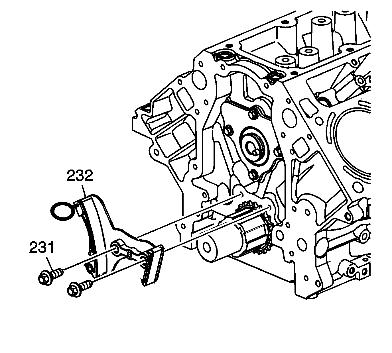
- Remove the bolts (231) and timing chain tensioner (232).
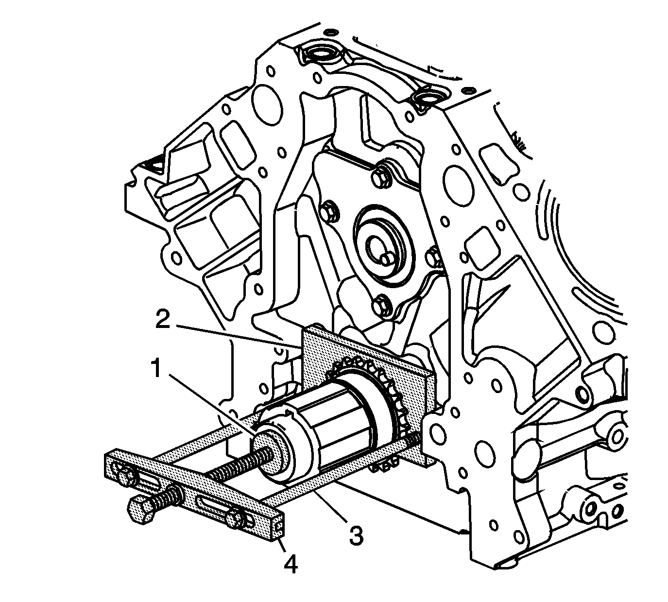
- Use the J 41816-2 (1), the J 41558 (2), bolts (3), and the J 8433 (4) in order to remove the crankshaft sprocket.
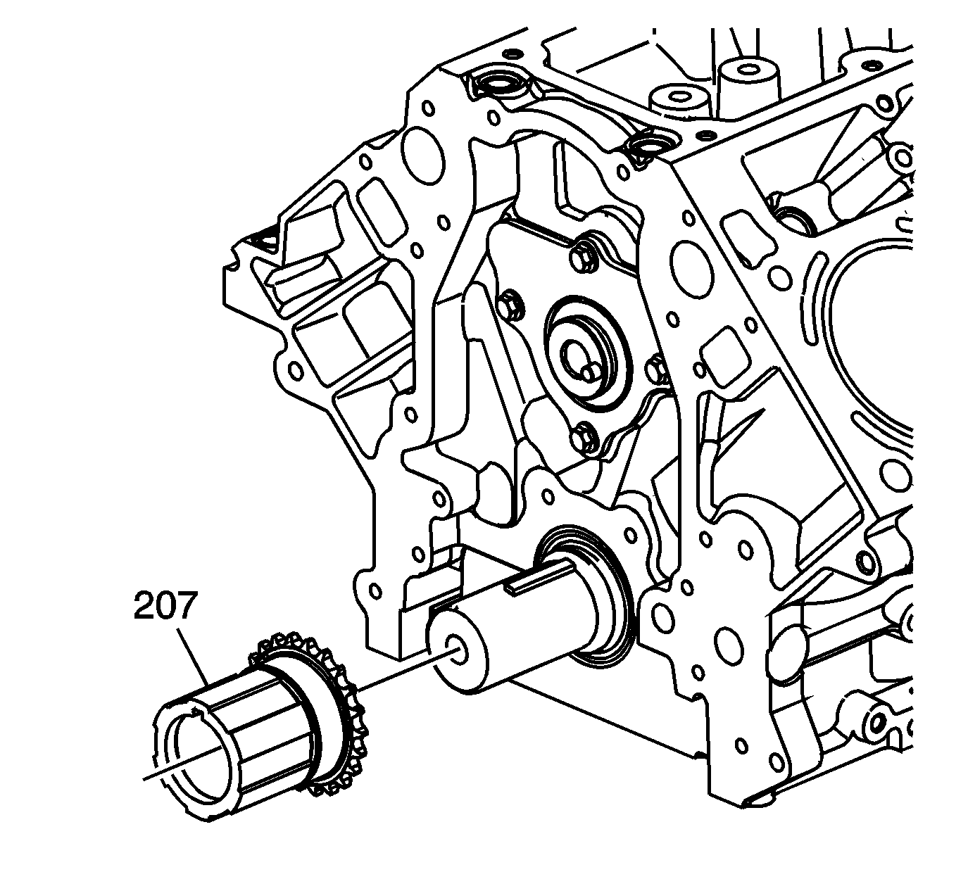
- Remove the crankshaft sprocket (207).
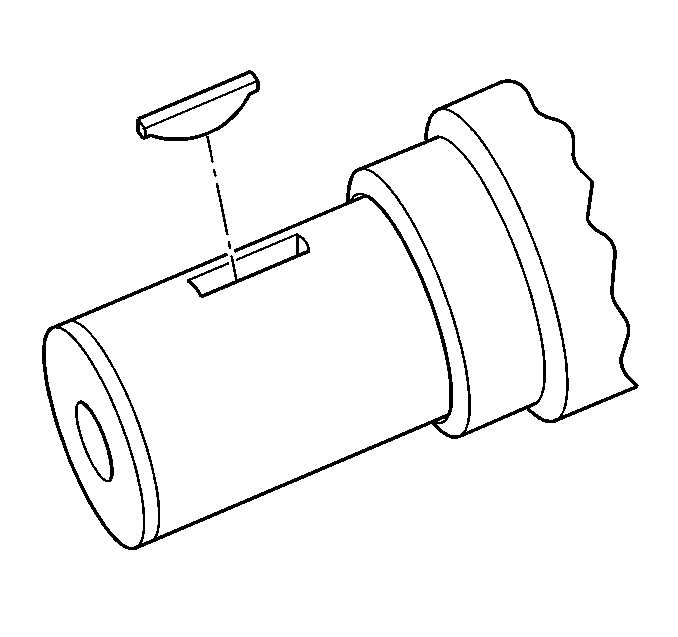
- Remove the crankshaft sprocket key, as required.
Notice: Do not turn the crankshaft assembly after the timing chain has been removed in order to prevent damage to the piston assemblies or the valves.
Installation Procedure
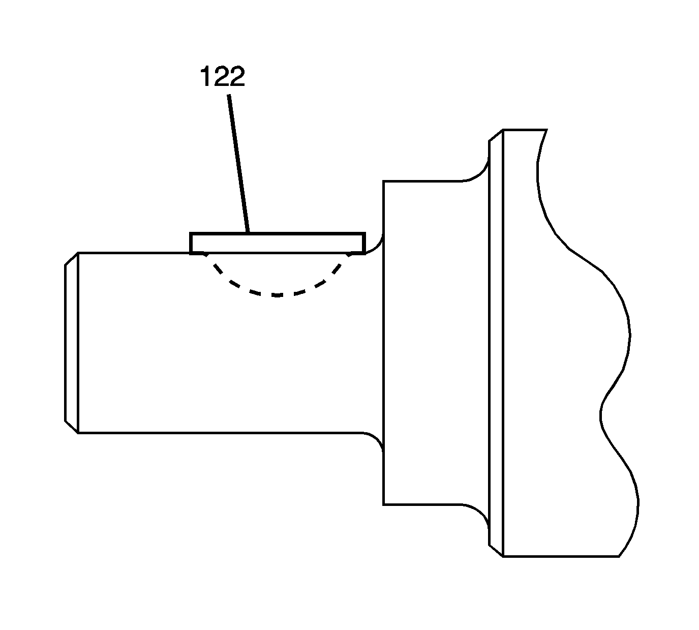
- Install the key into the crankshaft keyway, if previously removed.
- Tap the key (122) into the keyway until both ends of the key bottom onto the crankshaft.
- Install the crankshaft sprocket (207) onto the front of the crankshaft. Align the crankshaft key with the crankshaft sprocket keyway.
- Use the J 41478 (1) and the J 41665 (2) in order to install the crankshaft sprocket.
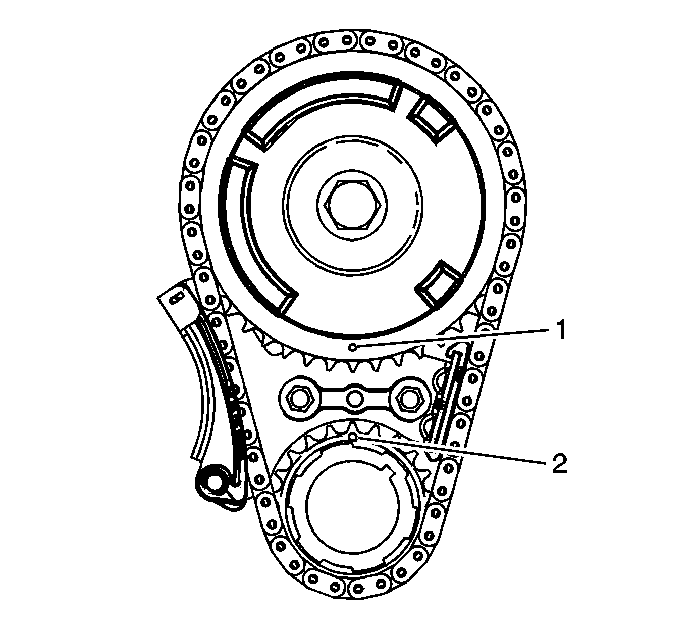
- Rotate the crankshaft sprocket until the alignment mark is in the 12 o'clock position.
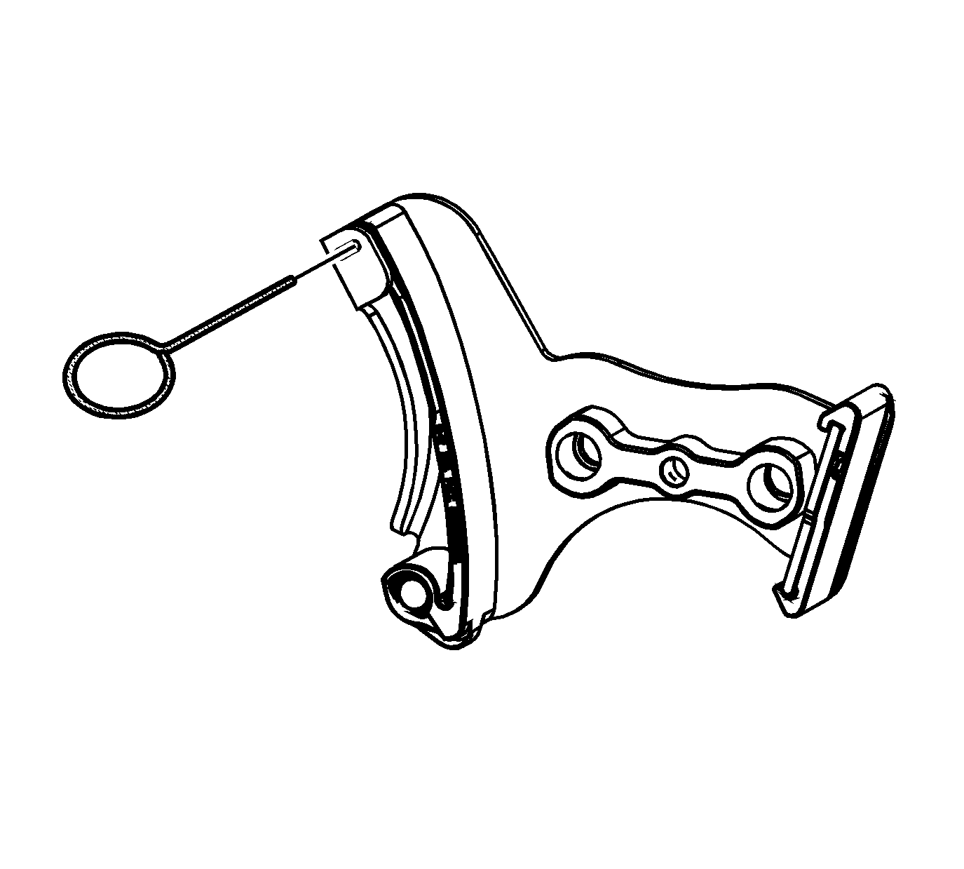
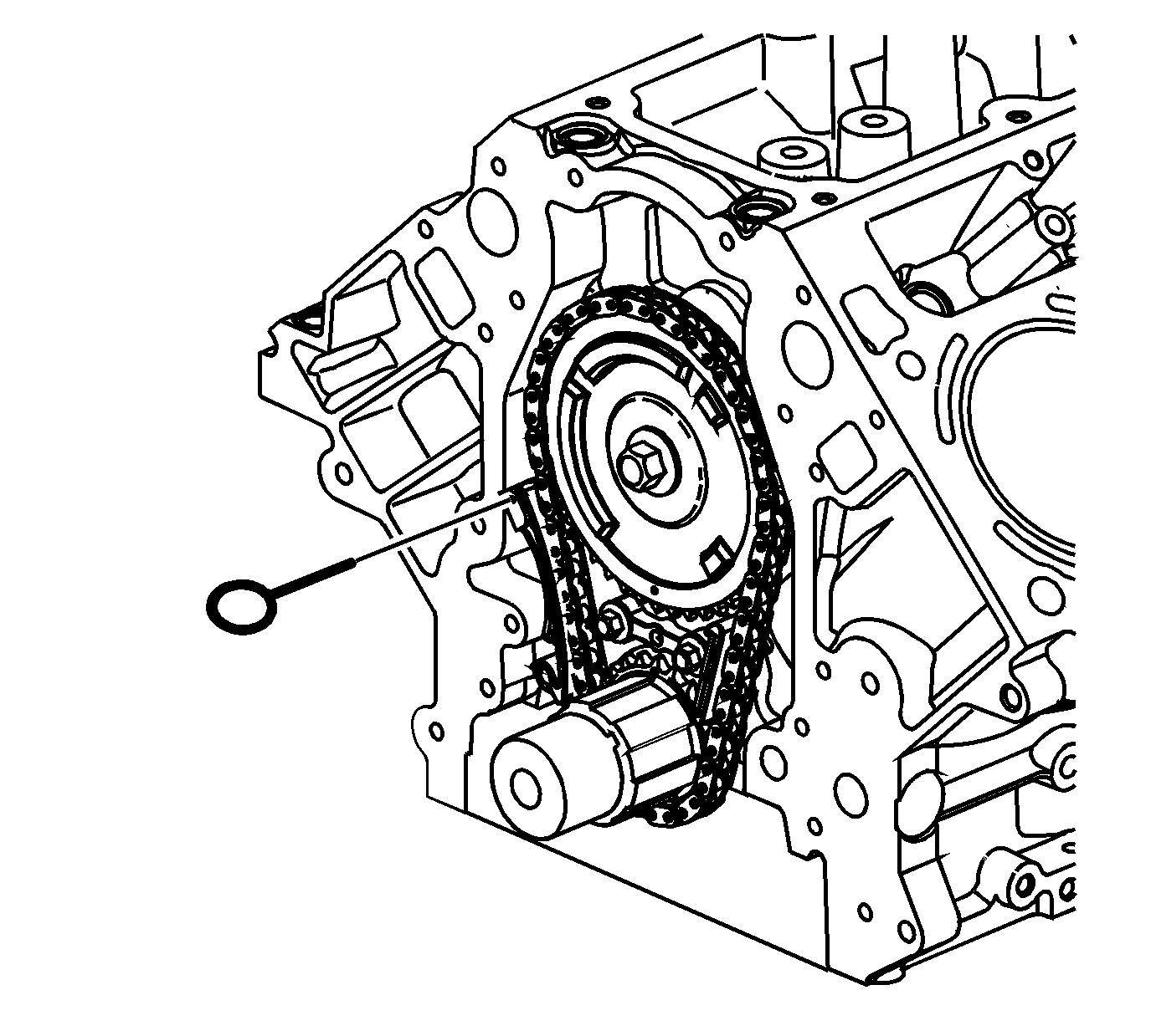
- Compress the timing chain tensioner guide and install the EN 46330 .
- Install the timing chain tensioner (232) and bolts (231).
- Install the camshaft sprocket (205), timing chain (208), and NEW bolt (206).
- Inspect the sprockets for proper alignment. The mark on the camshaft sprocket (1) should be located in the 6 o'clock position and the mark on the crankshaft sprocket (2) should be located in the 12 o'clock position.
- Remove the EN 46330 .
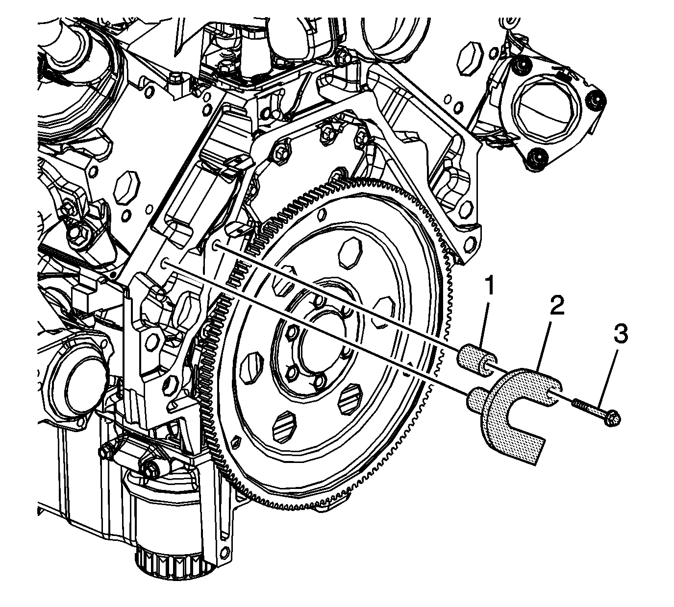
- Temporarily install the automatic transmission flex plate and bolts. Refer to Engine Flywheel Replacement .
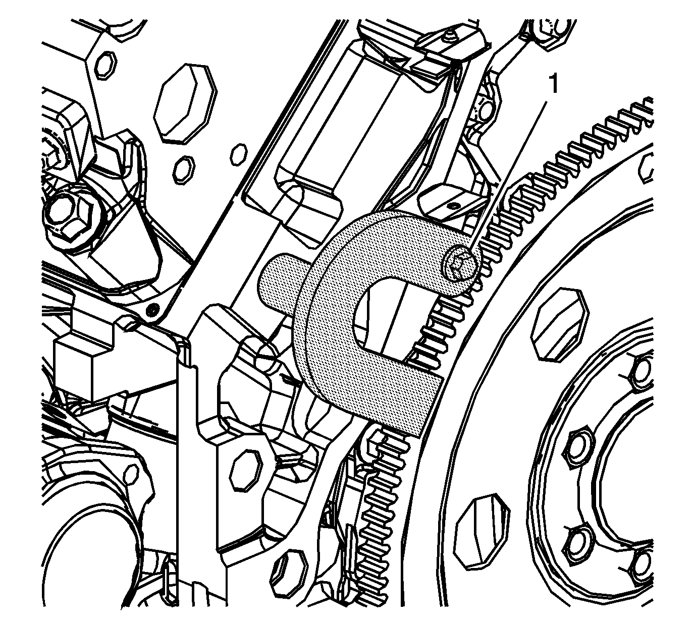
- Install the EN 47699 (2), spacer (1), and bolts (3) to the block and flex plate.
- Tighten the EN 47699 bolt (1).
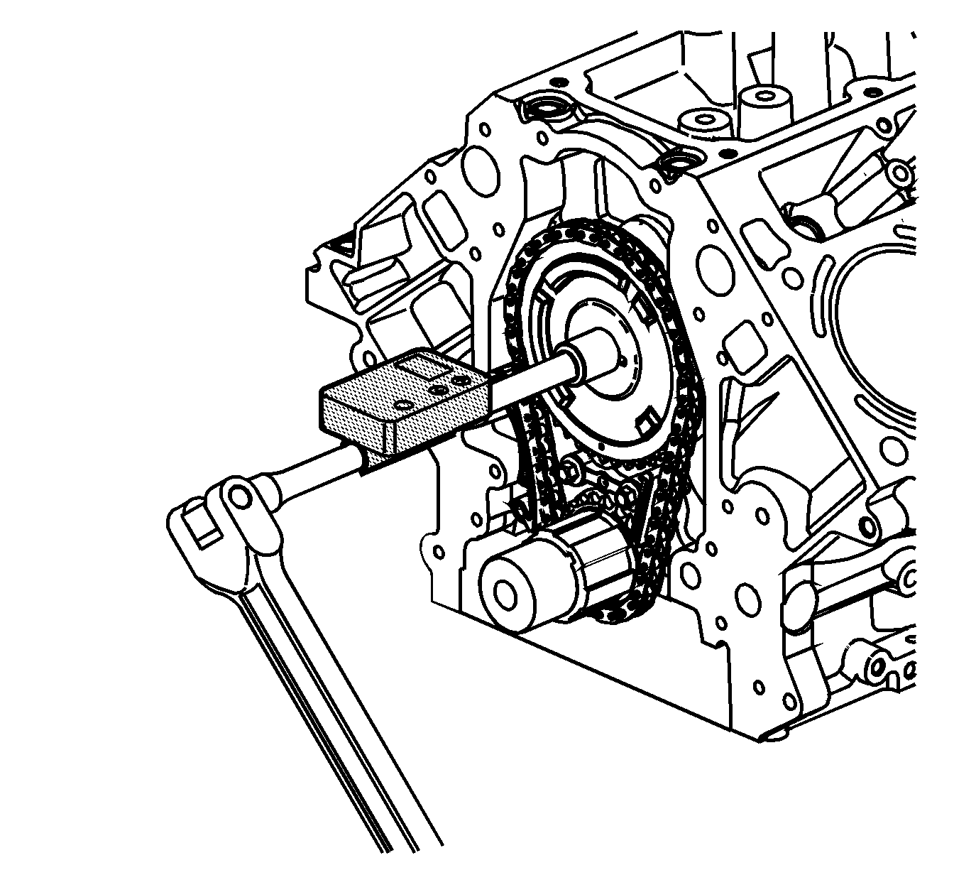
- Tighten the camshaft sprocket bolt.
- Tighten the camshaft sprocket bolt a first pass to 75 N·m (55 lb ft).
- Tighten the camshaft sprocket bolt a final pass an additional 50 degrees using the J 45059 .
- Remove the J 42386-A and bolts.
- Remove the automatic transmission flex plate and bolt. Refer to Engine Flywheel Removal .
- Install the oil pump. Refer to Oil Pump, Screen, and Crankshaft Oil Deflector Replacement .


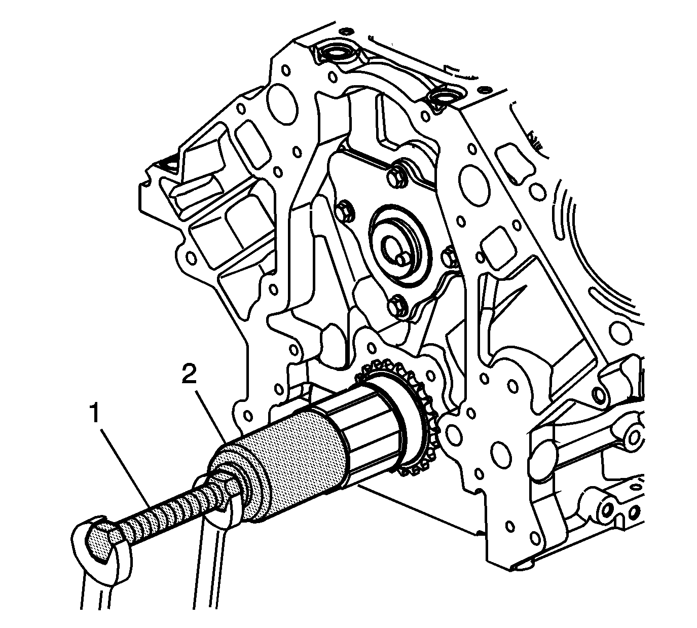
Install the sprocket onto the crankshaft until fully seated against the crankshaft flange.
Notice: Refer to Fastener Notice in the Preface section.
Tighten
Tighten the timing chain tensioner bolts to 25 N·m (18 lb ft).
Important:
• Do not use the camshaft sprocket bolt again. Install a NEW bolt during assembly. • The sprocket teeth and timing chain must mesh. • The camshaft and the crankshaft sprocket alignment marks MUST be aligned properly.
Important: Do not apply threadlock to the flex plate bolts at this time.
Tighten
Tighten the bolt to 60 N·m (44 lb ft).
Tighten
