Cylinder Deactivation (Active Fuel Management) Valve Lifter Oil Manifold Diagnosis and Testing for Pontiac Grand Prix 2008
Cylinder Deactivation (Active Fuel Management) Valve Lifter Oil Manifold Diagnosis and Testing 5.3L
Tools Required
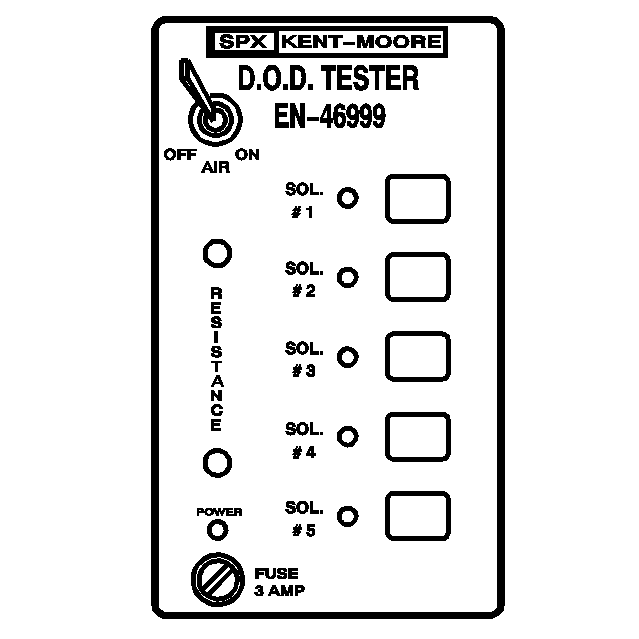
| • | EN-46999
Active Fuel Management Tester |
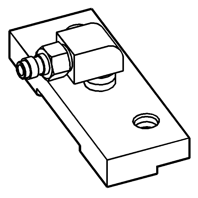
| • | EN-46999-1
Active Fuel Management Tester Air Adapter |
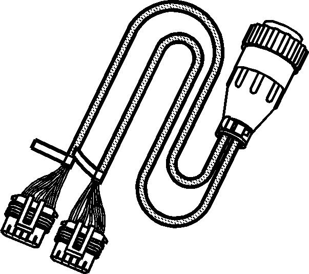
| • | EN-46999-5
Active Fuel Management Tester Harness - Small Block V8 |
Important:
| • | This component test applies only to vehicles with functional active fuel management. |
| • | A minimum shop air source of 206 kPa (30 psi) is required for manifold testing. |
| • | A water bleed is located on the
EN-46999
. Occasionally, depress the valve in order to remove excess water from the tool. |
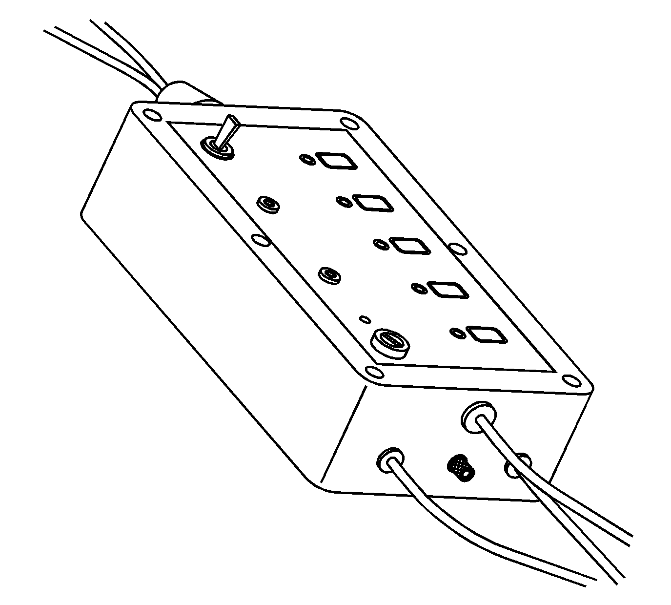
The manifold bench test provides a maximum 206 kPa (30 psi) of filtered shop air to the manifold and will test each solenoid/valve for the following conditions:
| • | A stuck open condition - constant air flow |
| • | A stuck closed condition - no air flow |
| • | A flow restriction within the manifold |
- Individually depress each of the buttons 1-4 on the
EN-46999
in order to activate each of the solenoid/valves. When activating each solenoid/valve, a loud click should be heard from
the solenoid and an increased amount of air will exit the outlet ports.
| • | Button 1 will energize the solenoid/valve 1 for engine cylinder number 1. |
| • | Button 2 will energize the solenoid/valve 2 for engine cylinder number 4. |
| • | Button 3 will energize the solenoid/valve 3 for engine cylinder number 6. |
| • | Button 4 will energize the solenoid/valve 4 for engine cylinder number 7. |
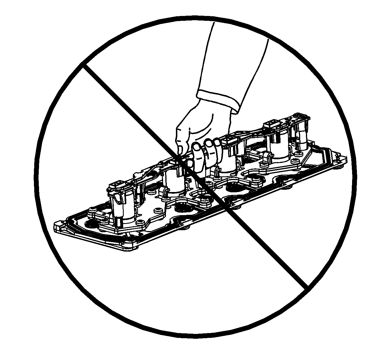
- Do not lift the manifold assembly by
the electrical lead frame.
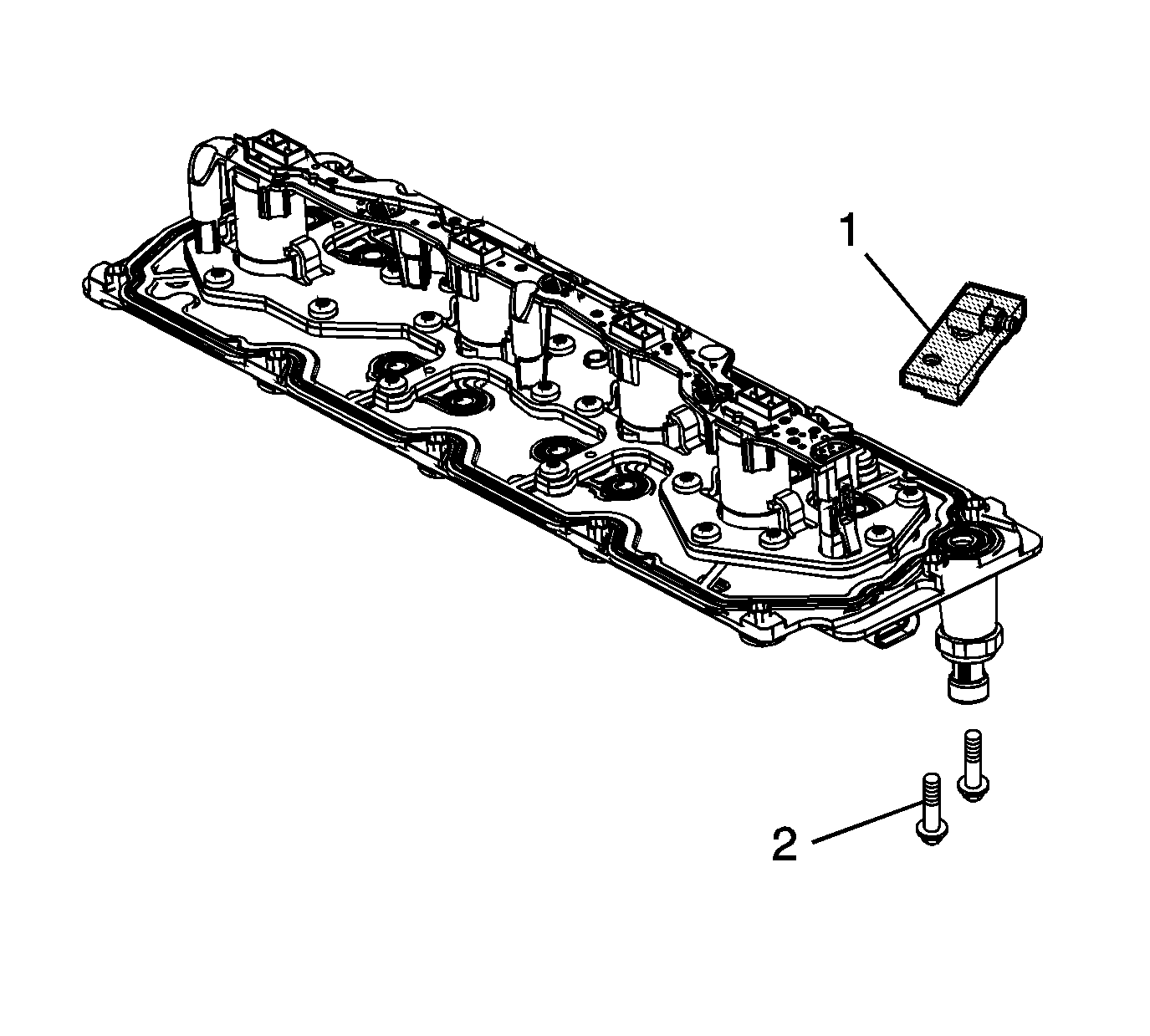
- Install the
EN-46999-1
(1)
to the manifold.
Notice: Refer to Fastener Notice in the Preface section.
- Install 2 of the manifold bolts (2) to the
EN-46999-1
.
Tighten
Tighten the bolts to 25 N·m (18 lb ft).
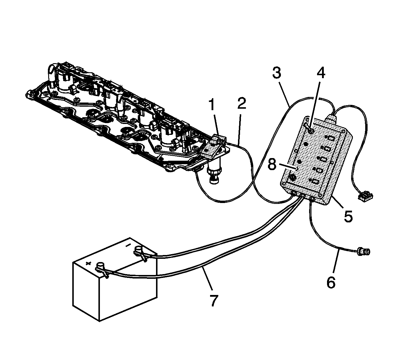
- Connect the air out hose (2) of the
EN-46999
(5) to the
EN-46999-1
(1). Verify the air supply switch (4) is in the off position.
- Connect the air in hose (6) of the
EN-46999
(5) to a shop air source.
- Connect the 12-volt power supply connectors (7) of the
EN-46999
(5) to a 12-volt power supply. Verify the Power light (8) on the tool is illuminated. If the
light on the tool is not illuminated when connected to a 12-volt power supply, test and/or replace the 3 amp fuse.
- Connect the
EN-46999-5
power cable (3) to the electrical connector of the manifold.
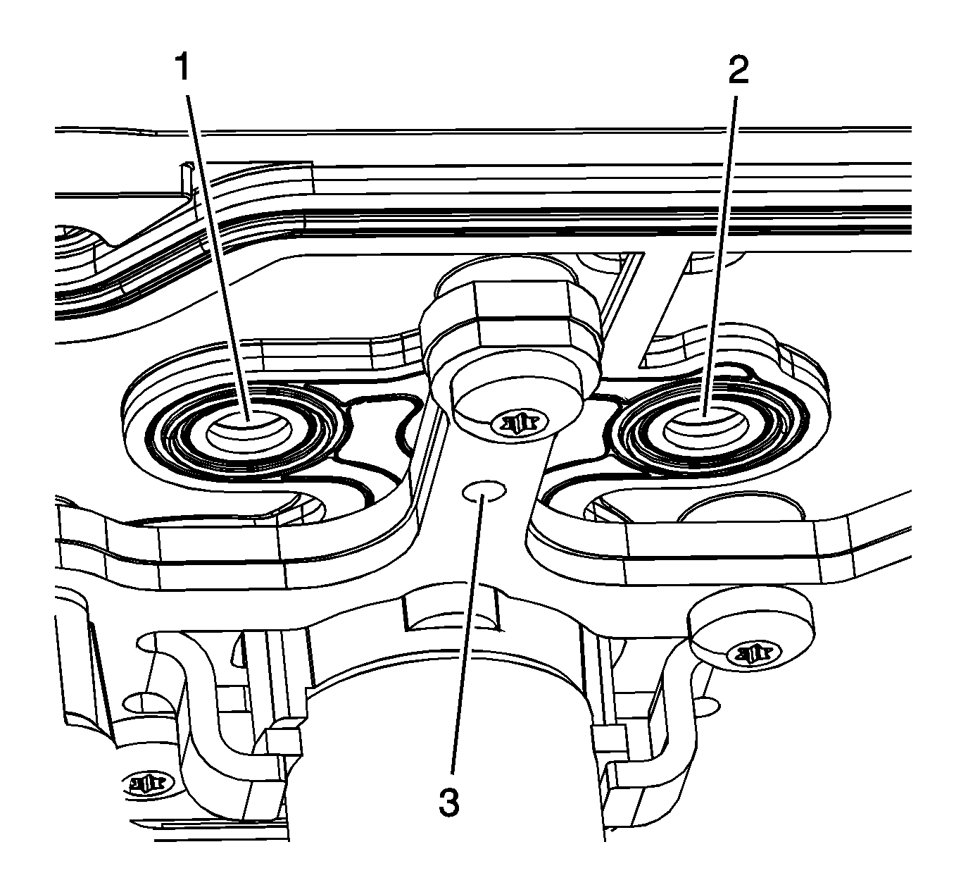
- Turn the air supply switch of the
EN-46999
to the ON position. With the air supply connected to the manifold assembly and the solenoid/valves in the closed position, a limited amount of air will exit each of the bleed holes (3) and outlet ports (1,
2) of the manifold.
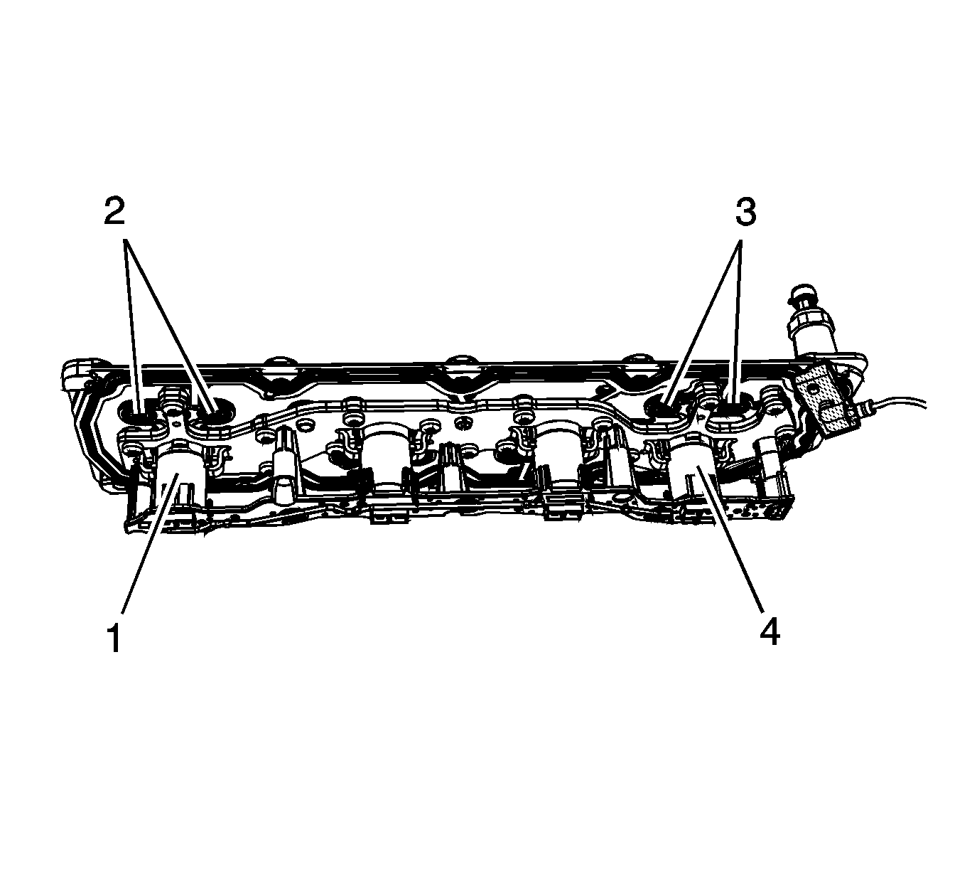
Important: The manifold must be tested in the proper position to ensure the solenoid/valves operate as designed.
- Position the manifold assembly onto a bench at a 45 degree angle in order to test solenoid/valves 1 and 4.
- Depress button number 1 on the tool to activate solenoid/valve 1. With button 1 depressed, the solenoid/valve (1) should open, allowing an increased amount of air to exit the outlet ports (2) of the manifold.
- Depress button number 4 on the tool to activate solenoid/valve 4. With button 4 depressed, the solenoid/valve (4) should open, allowing an increased amount of air to exit the outlet ports (3) of the manifold.
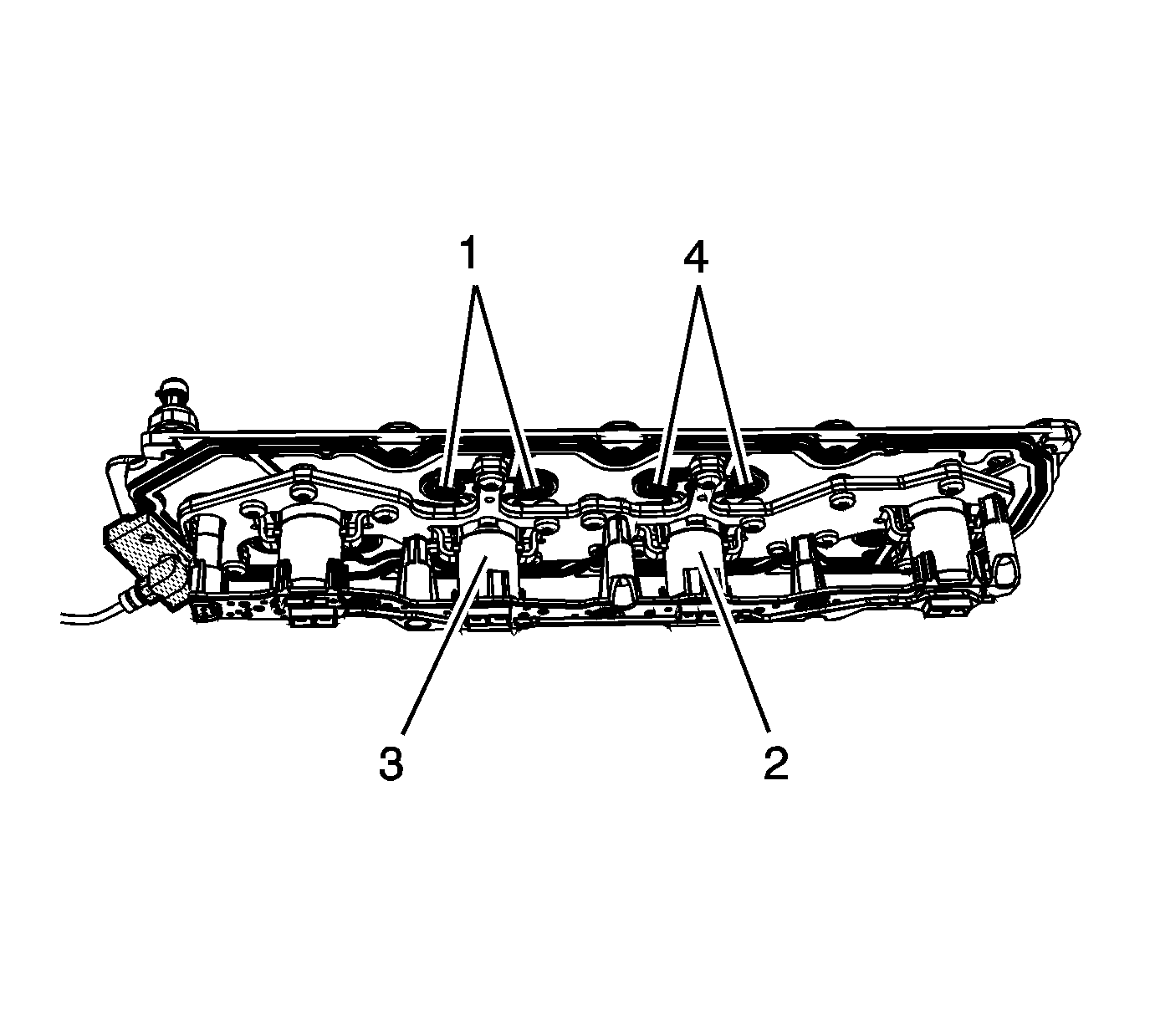
- Reposition the manifold assembly onto a bench at a 45 degree angle in order
to test solenoid/valves 2 and 3.
- Depress button number 2 on the tool to activate solenoid/valve 2. With button 2 depressed, the solenoid/valve (2) should open, allowing an increased amount of air to exit the outlet ports (4) of the manifold.
- Depress button number 3 on the tool to activate solenoid/valve 3. With button 3 depressed, the solenoid/valve (3) should open, allowing an increased amount of air to exit the outlet ports (1) of the manifold.
- When the test is completed, turn the air source switch on the
EN-46999
to the off position and disconnect the tool from the 12-volt power supply, shop air source and manifold assembly.
- If after testing, it has been determined that 1 or more of the solenoid/valves is not functioning properly, replace the manifold as an assembly.
- If after testing, it has been determined that the solenoid/valves are functioning properly, replace the valve lifters, as required. Both intake and exhaust lifters should be replaced in pairs.