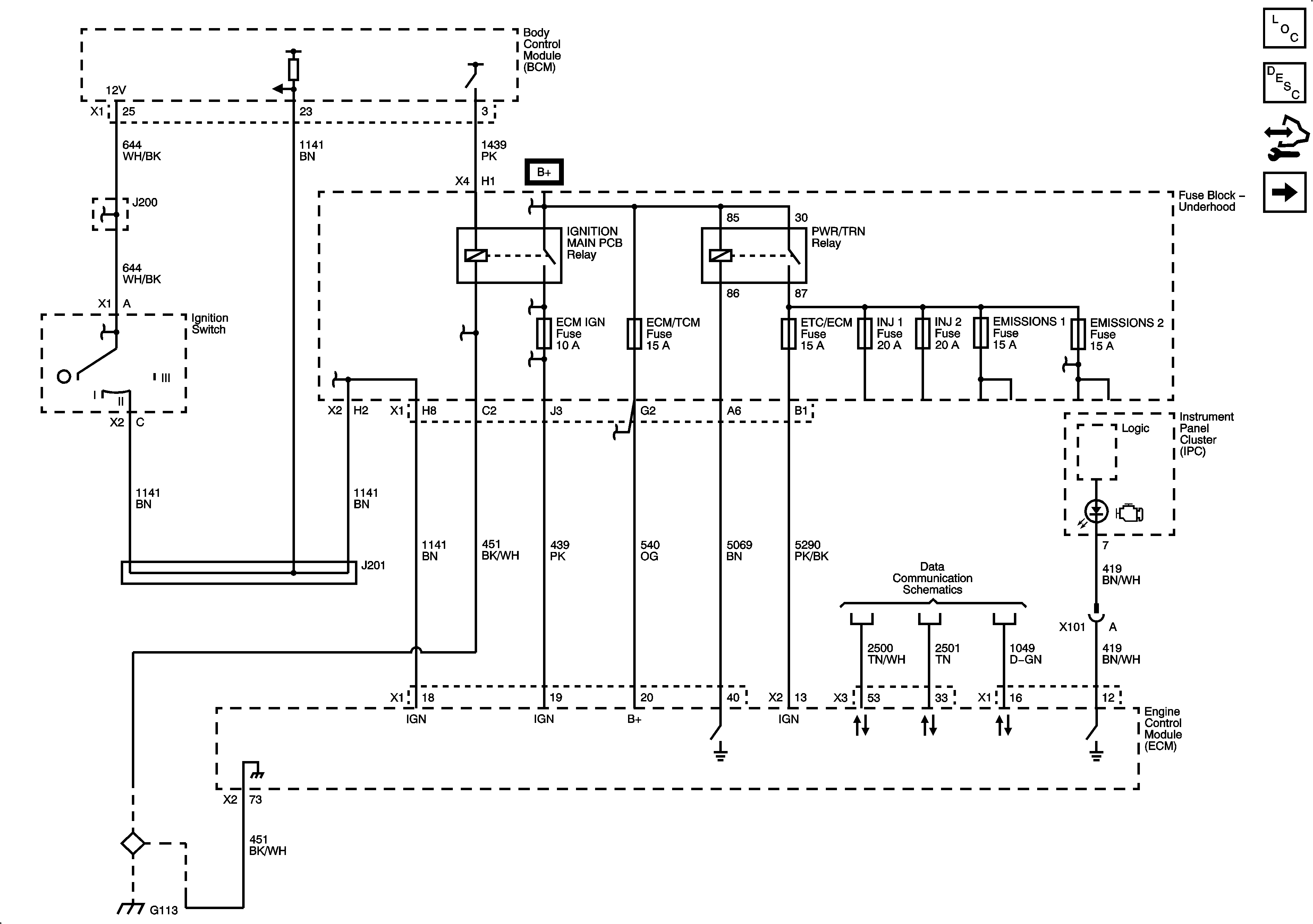
| Figure 1: |
PCM Power, Ground, MIL and Serial Data
|
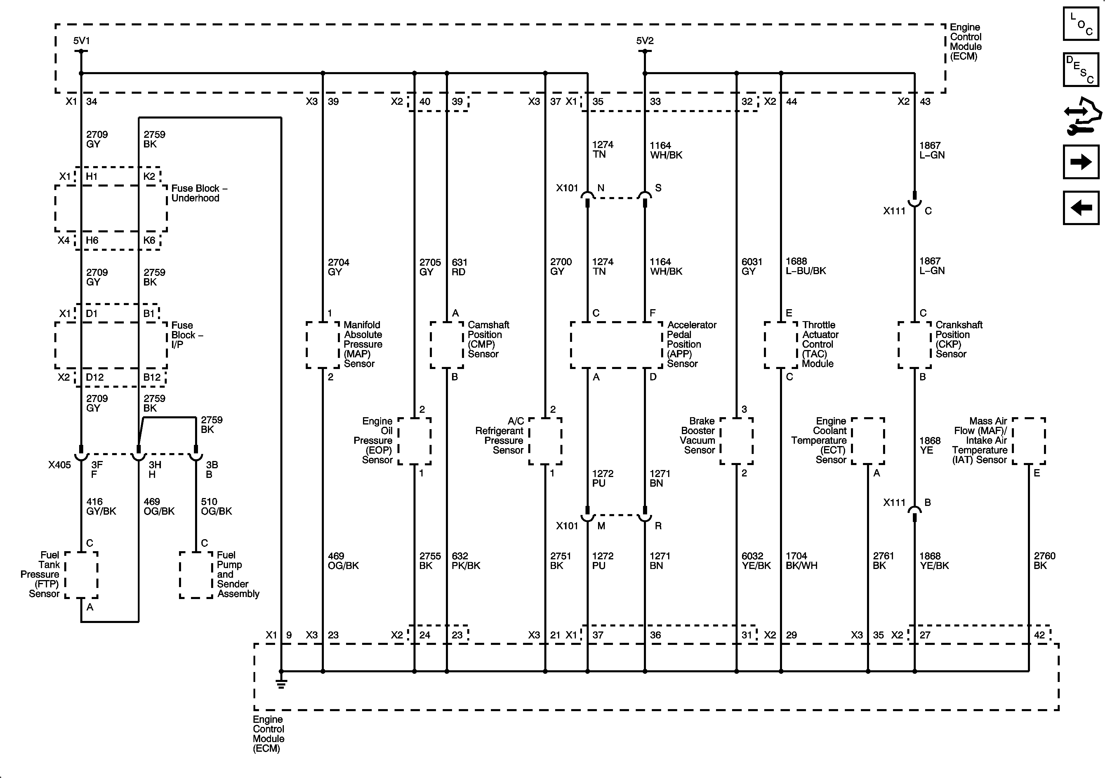
| Figure 2: |
5-Volt and Low Reference Bussing
|
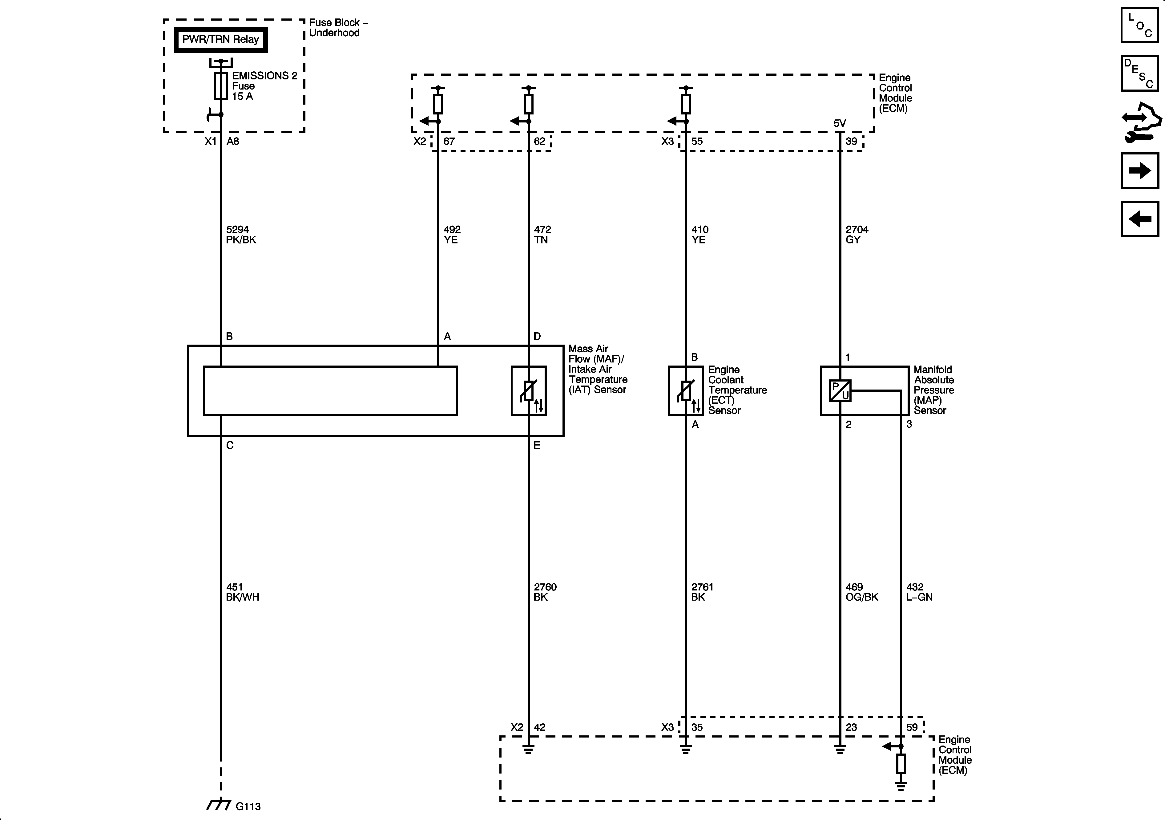
| Figure 3: |
MAP, ECT, and MAF/IAT Sensors
|
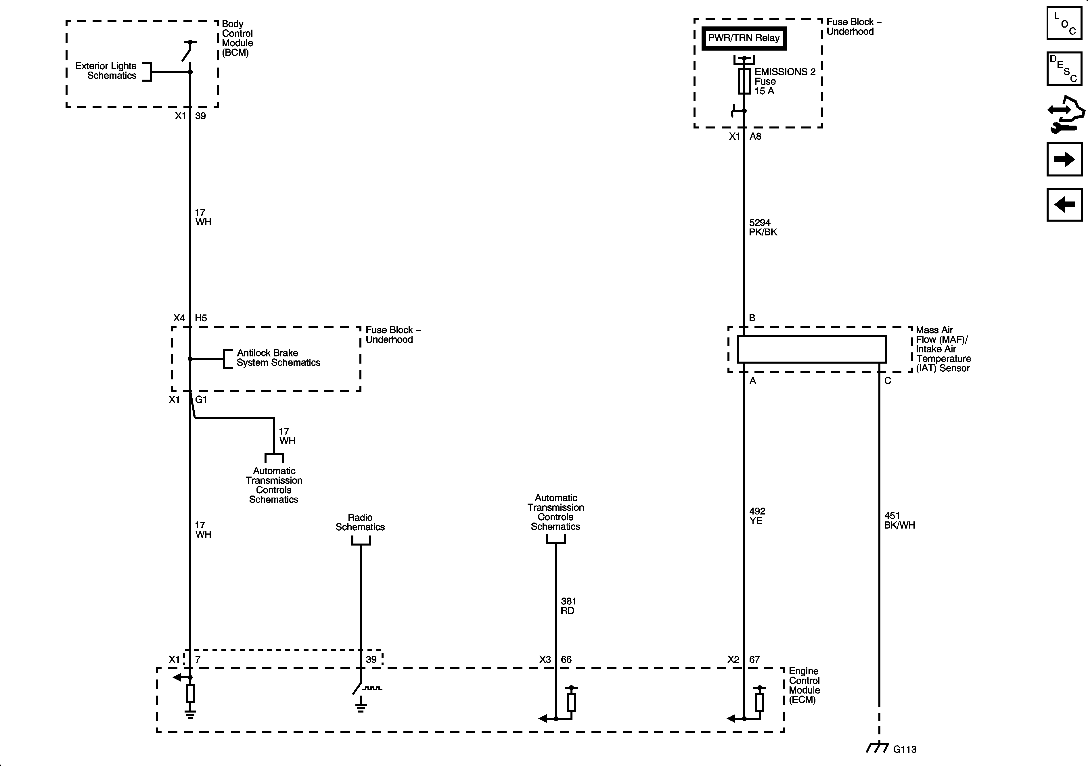
| Figure 4: |
MAP/IAT Sensor, Stop Lamp Switch Signal and VSS
|
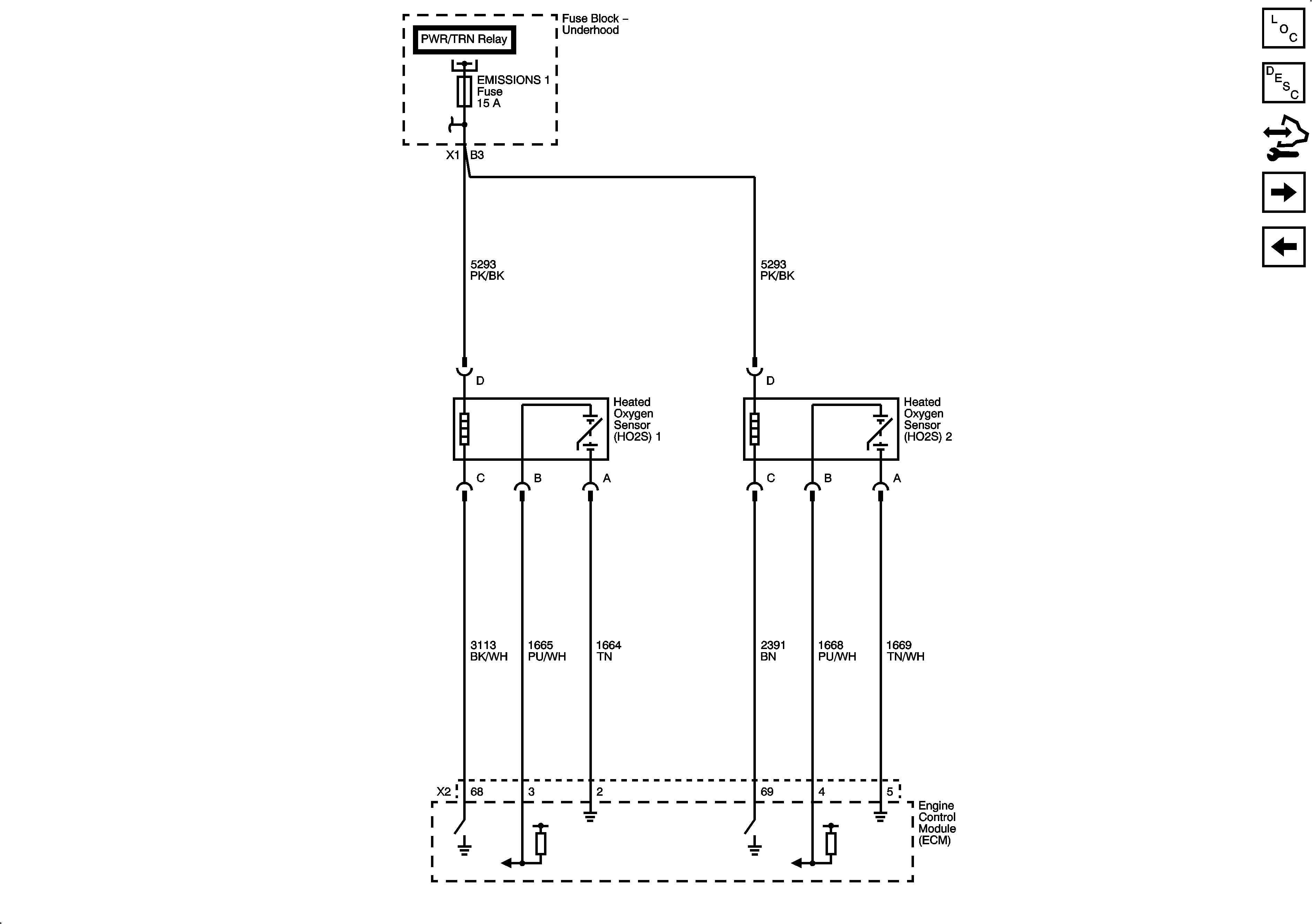
| Figure 5: |
Heated Oxygen Sensors
|
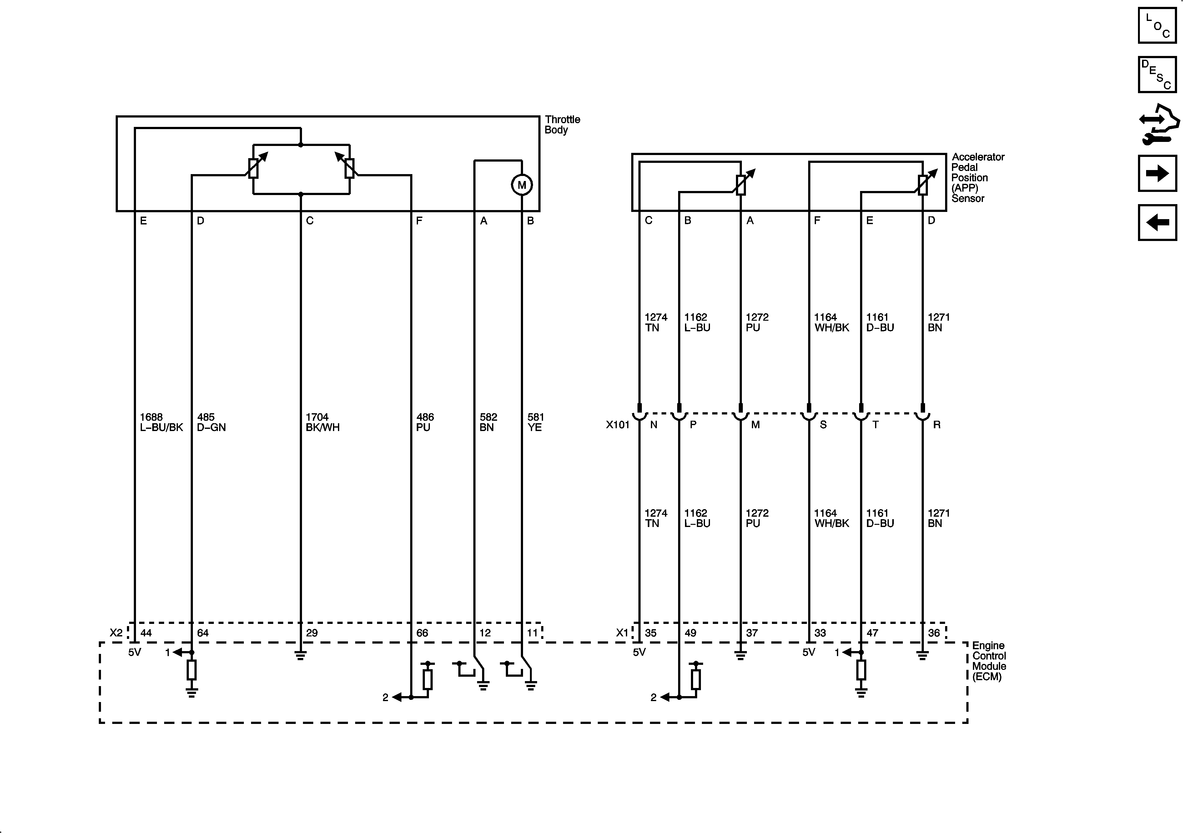
| Figure 6: |
Electronic Throttle Controls
|
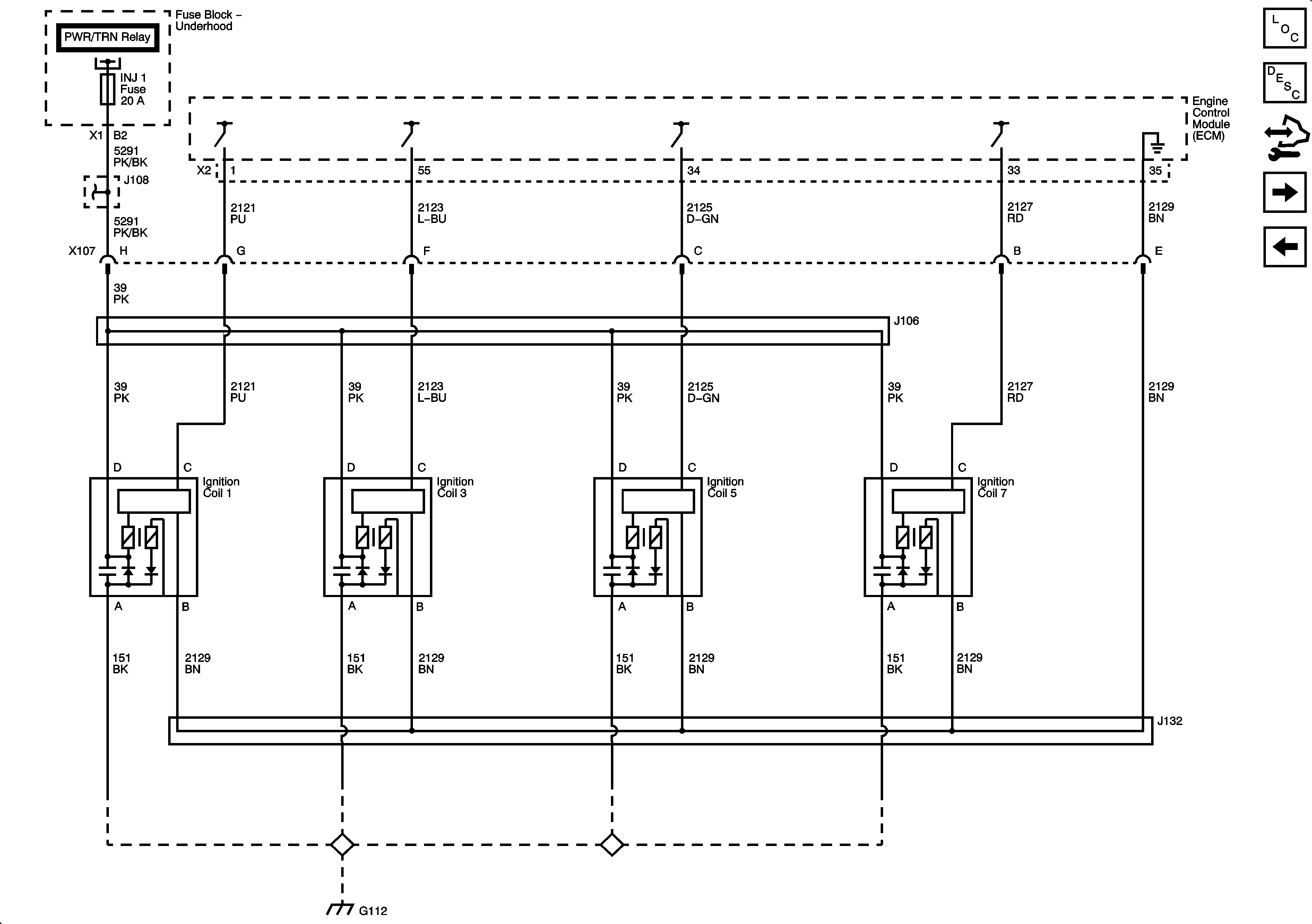
| Figure 7: |
Ignition Controls Bank 1 Ignition Coils 1, 3, 5, and 7
|
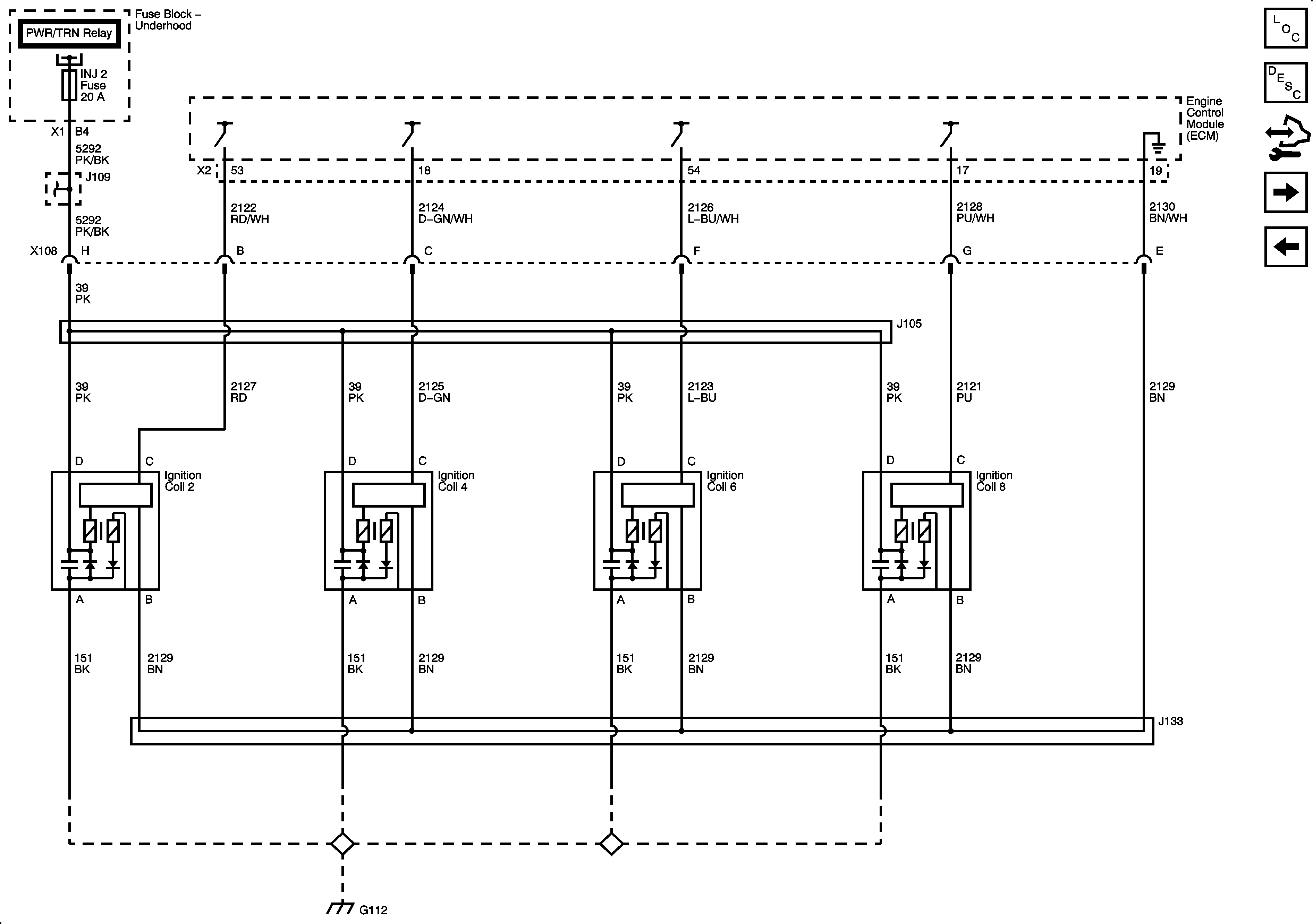
| Figure 8: |
Ignition Controls Bank 2 Ignition Coils 2, 4, 6, and 8
|
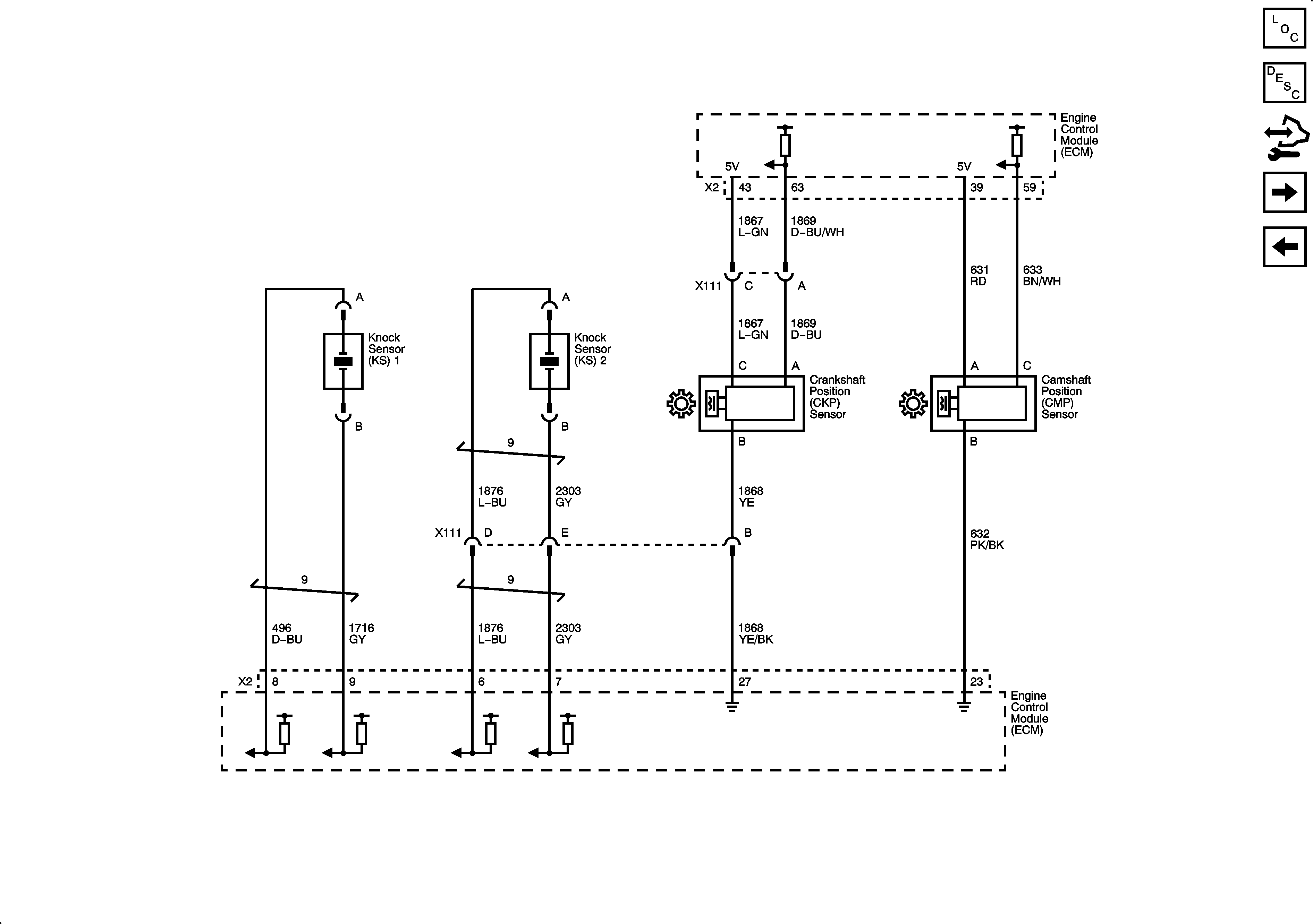
| Figure 9: |
Ignition Controls Knock, CMP, CKP, Brake Vacuum Sensors and Valve Lifter Oil Manifold Assembly
|
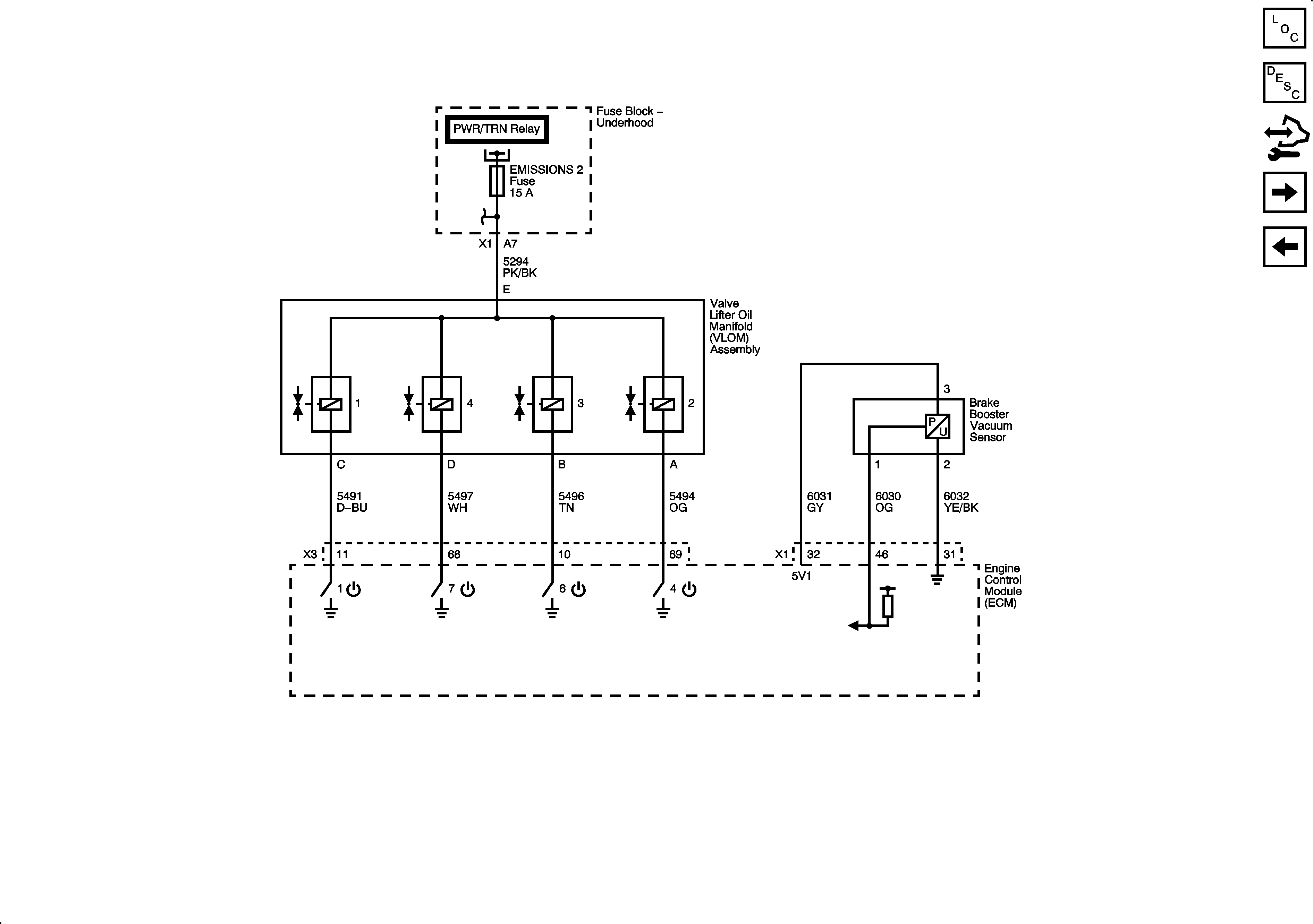
| Figure 10: |
Fuel Pump Controls
|
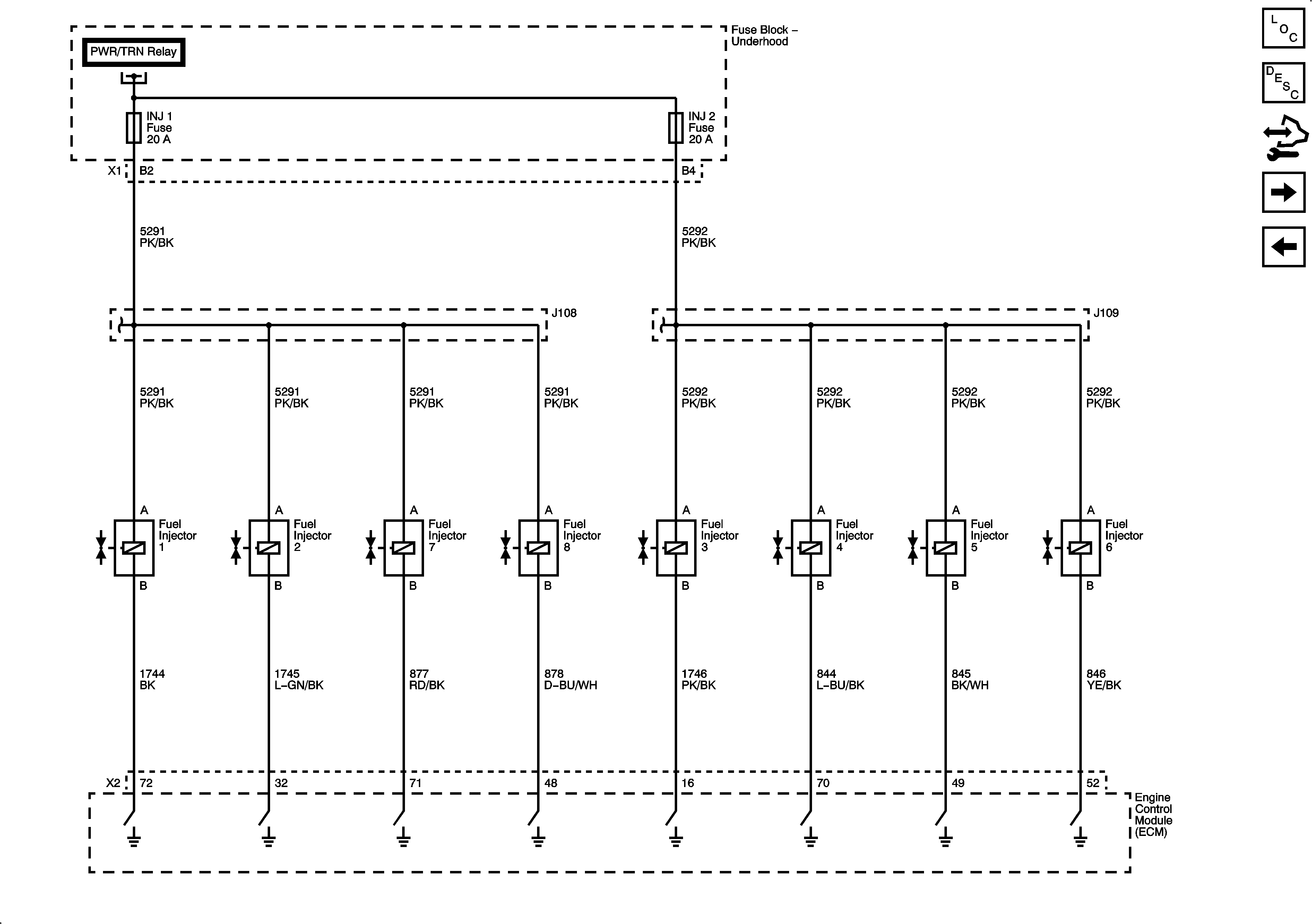
| Figure 11: |
Fuel Injectors
|
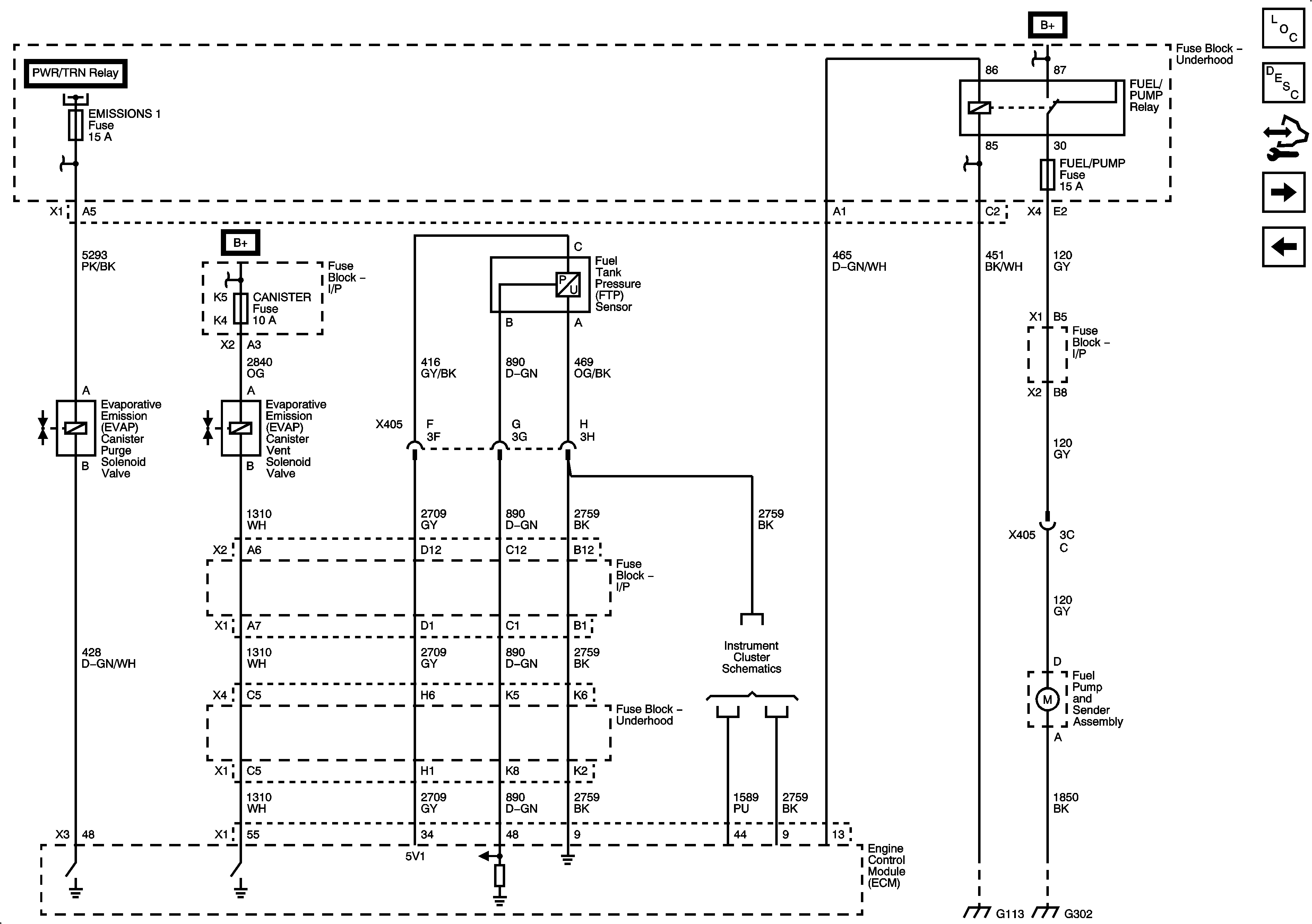
| Figure 12: |
EVAP Solenoids and FTP Sensor
|
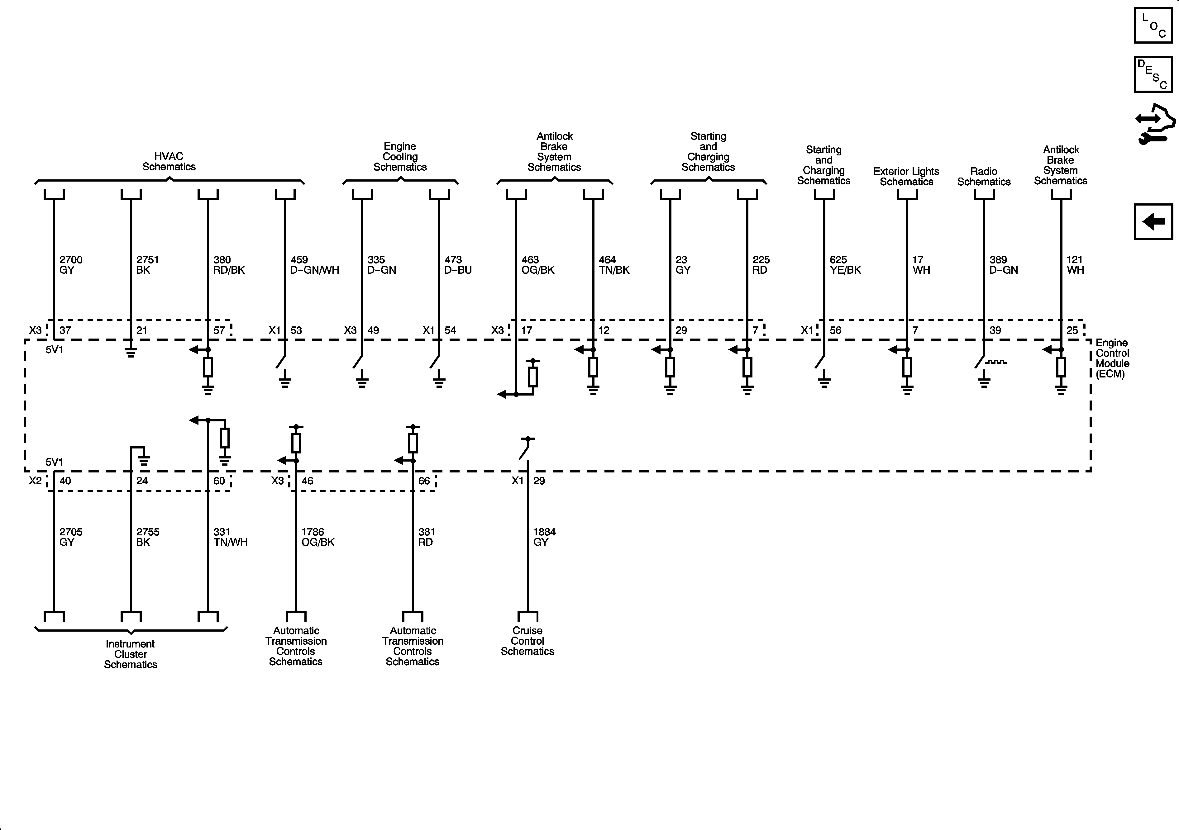
| Figure 13: |
Controlled/Monitored Subsystem References
|


