MIXTURE CONTROL ADJUST NEW SPECIFICATIONS

Subject: REVISED MIXTURE CONTROL ADJUSTMENTS AND SPECIFICATIONS FOR 1978-1982 COMPUTER COMMAND CONTROL DUALJET AND QUADRAJET CARBURETORS (FEDERAL AND CALIFORNIA)
Some important changes have been made in the procedures for adjusting the Lean and Rich Mixture Screws and the Idle Air Bleed Valve on Computer Command Controlled Quadrajet and Dualjet carburetors. The new procedure involves making the settings to a dimension, rather than to a certain number of screw turns. It is still possible to adjust a carburetor following an overhaul or if a System Performance check indicates this is required.
The new procedure applies to all "Closed Loop" Dualjet and Quadrajets (E2MC, E2ME, E4MC and E4ME) carburetors and should be used in place of all other procedures. Revised specifications for these adjustments are included in this bulletin and should also be used in place of all other published specifications.
MIXTURE CONTROL SOLENOID PLUNGER ADJUSTMENTS
Installing Mixture Control Solenoid
1. Remove air horn, mixture control solenoid plunger, air horn gasket and plastic filler block, using normal service procedures.
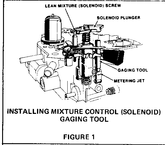
2. Remove metering rod on throttle bellcrank side of carburetor and install the mixture control solenoid gaging tool (J-33815-1, BT-8253-A) or equivalent, over the metering jet rod guide and reinstall the solenoid plunger (see Figure 1).
Adjusting Lean & Rich Mixture Solenoid Screws
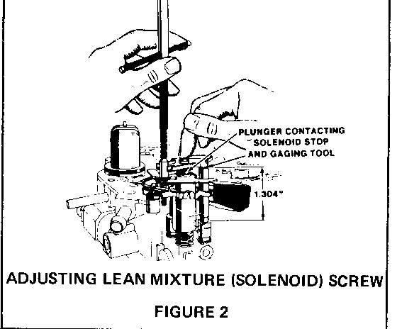
1. Hold the solenoid plunger down, against the solenoid stop or gaging tool, and use tool (J-28696-10, BT-7928) or equivalent, to turn lean mixture screw until the plunger just breaks contact with the gaging tool. Then, turn lean mixture screw slowly until the plunger just contacts the gaging tool. The adjustment is correct when the solenoid plunger contacts both the solenoid stop and the gaging tool (see Figure 2 on the following page).
2. Remove gaging tool and reinstall metering rod, plastic filler block and air horn gasket.
3. Remove lean and rich mixture adjustment screw plugs and back out the rich mixture stop screw. Reassemble the carburetor.
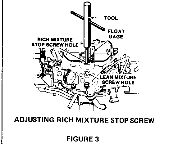
4. Insert external float gage (J-9789-130, BT-7720) or equivalent in vent hole. Use tool (J-28696-10, BT-7928) or equivalent to adjust rich mixture stop screw to obtain 4/32 inch total plunger travel (see Figure 3 on following page).
5. Install new screw plugs supplied in service kit.
Idle Air Bleed Valve Adjustment - Check For Letter Identification
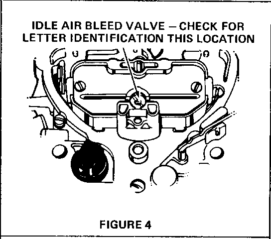
With cover removed from the Idle Air Bleed Valve, look for the presence (or absence) of an identifying letter on the top face of the valve (see Figure 4).
o If there is NO letter, continue on using PROCEDURE A.
o If there is a letter, use PROCEDURE B (on next page).
PROCEDURE A (No Letter On Idle Air Bleed Valve)
1. Presetting The Idle Air Bleed Valve - (Only necessary if idle air bleed valve was serviced prior to on-vehicle adjustment.)
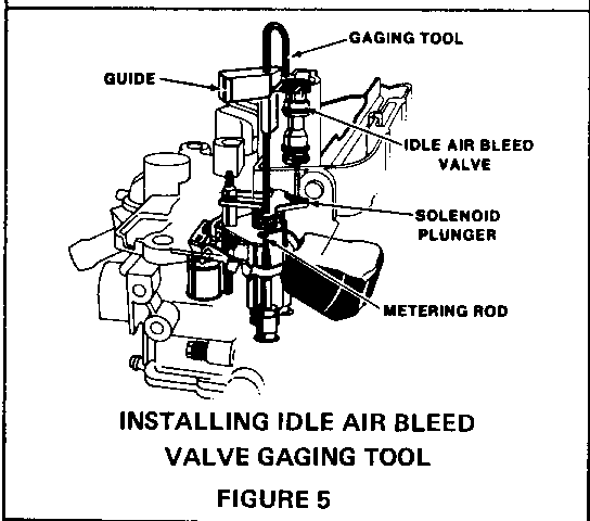
Install idle air bleed valve gaging tool (J-33815-2, BT-8253-B) or equivalent in "D" shaped vent hole of the air horn casting (see Figure 5). The bottom end of the gaging tool should now be resting on the solenoid plunger. The upper end of the tool should be positioned over the open cavity next to the idle air bleed valve.
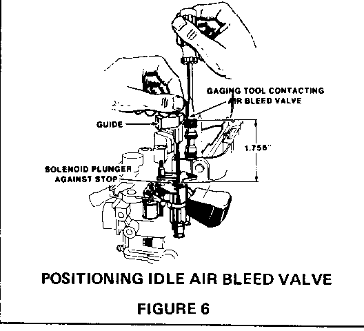
2. Hold the gaging tool down lightly, so that the solenoid plunger is against the solenoid stop, and adjust the idle air bleed valve so that the gaging tool will pivot over and just contact the top of the valve. The valve is now preset for on-vehicle adjustments (see Figure 6 on the following page).
3. Remove gaging tool.
4. Adjusting The Idle Air Bleed Valve - Block drive wheels, place transmission in park (auto- matic transmission) or neutral (manual trans- mission) and set parking brake. Start engine and allow it to reach normal operating temperature in closed loop.
5. While idling in drive (neutral for manual transmission), slowly turn the air bleed valve clockwise or counterclockwise, until the dwell reading varies within the 25-30 degree range, attempting to be as close to 30 deg. as possible. The air bleed valve is very sensitive and should only be turned an 1/8 turn at a time.
6. If the dwell reading does not vary and cannot be adjusted within the 25-30 deg. range, it may be necessary to adjust the idle mixture needles.
7. Setting The Idle Mixture Needles (If necessary) Remove idle mixture needle plugs. Use tool (J-29030-B, BT-7610B) or equivalent to turn both idle mixture needles clockwise until they are lightly seated, then turn each mixture screw counterclockwise the number of turns specified on the attached specifications.
8. Readjusting Idle Air Bleed Valve - Start engine and run until fully warm and repeat Steps 4 and 5.
9. If you are still unable to set the dwell between 25-30 deg., and the dwell is below 25 deg., turn both mixture needles counterclockwise one additional turn. If the dwell is above 35 deg., turn both mixture needles clockwise one additional turn. Be sure to readjust the idle air bleed valve to obtain the preferred dwell (Steps 4 and 5).
10. Seal the idle mixture needle openings using silicone sealant (RTV). Sealing is required to prevent any fuel vapor loss.
11. Perform Idle Speed adjustments as necessary.
PROCEDURE B (Letter On Idle Air Bleed Valve)
1. Pre-Setting The Idle Air Bleed Valve - Install the air bleed valve gaging tool (J-33815-2, BT-8253-B) or equivalent in "D" shaped vent hole of the air horn casting (refer to Figure 5). The bottom end of the gaging tool should now be resting on the solenoid plunger. The upper end of the tool should be positioned over the open cavity next to the idle air bleed valve.
2. Hold the gaging tool down lightly, so that the solenoid plunger is against the solenoid stop, and adjust the idle air bleed valve so that the gaging tool will pivot over and just contact the top of the valve. The valve is now preset for on-vehicle adjustments (refer to Figure 6).
3. Remove gaging tool.
4. Adjusting The Idle Mixture Needles - Remove the idle mixture needle plugs. Use tool (J-29030-B, BT-7610-B) or equivalent to turn each idle mixture needle clockwise until lightly seated, then turn each mixture needle counterclockwise three turns out.
5. Adjusting The Idle Air Bleed Valve - Block drive wheels, place transmission in park (automatic transmission) or neutral (manual transmission) and set the parking brake. Start the engine and allow it to reach normal operating temperature in closed loop.
6. While idling in drive (neutral for manual transmission), adjust both idle mixture needles equally, 1/8 turn at a time, until the dwell reading varies within the 25-10 deg. range. If reading is too low, turn mixture needles counterclockwise. If reading is too high, turn mixture needles clockwise. Allow time for dwell reading to stabilize after each adjustment.
7. After all adjustments are complete, seal the idle mixture needle openings using silicone sealant (RTV). The sealer is required to prevent any fuel vapor loss.
8. Perform Idle Speed adjustments as necessary.
MIXTURE CONTROL ADJUSTMENTS -QUADRAJET - E4MC - E4ME
Notes:
1. G = Gage 2. Preset 1.756G, final adjustment on vehicle 3. Preset 3 turns, final adjustment on vehicle
LEAN RICH IDLE IDLE CARB. MIXT. MIXT. MIXT. AIR NUMBER SCREW SCREW NEEDLE BLEED ---------- ------ ----- ------ ------- 17080502 1.304G 4/32 1 1/4 NOTE 2 CHV 5.0 V8
17080504 1.304G 4/32 1 1/4 NOTE 2 CHV 5.0 V8
17080516 1.304G 4/32 2 1/4 NOTE 2 CHV 5.0 V8
17080517 1.304G 4/32 1 3/4 NOTE 2 CHV 5.0 V8
17080530 1.304G 4/32 5 NOTE 2 CAD 6.0 V8
17080540 1.304G 4/32 5 1/4 NOTE 2 BCK 3.8 V6
17080542 BCK 3.8 V6 1.304G 4/32 5 3/4 NOTE 2
17080543 1.304G 4/32 5 3/4 NOTE 2 BCK 3.8 V6
17080545 1.304G 4/32 5 1/4 NOTE 2 BCK 3.8 V6
17080553 1.304G 4/32 4 3/4 NOTE 2 OLD 5.7 V8
17080554 1.304G 4/32 4 3/4 NOTE 2 OLD 5.7 V8
17081202 1.304G 4/32 3 NOTE 2 CHV 5.0 V8
17081203 1.304G 4/32 3 NOTE 2 CHV 5.0 V8
17081204 1.304G 4/32 3 1/4 NOTE 2 CHV 5.0 V8
17081207 1.304G 4/32 3 NOTE 2 CHV 5.0 V8
17081216 1.304G 4/32 3 1/2 NOTE 2 CHV 5.7 V8
17081217 CHV 5.0 V8 1.304G 4/32 3 3/4 NOTE 2
17081218 1.304G 4/32 3 3/4 NOTE 2 CHV 5.7 V8
17081219 1.304G 4/32 3 NOTE 2 CHV 5.0 V8
17081222 1.304G 4/32 3 1/4 NOTE 2 CHV 5.0 V8
17081224 1.304G 4/32 3 1/2 NOTE 2 CHV 5.7 V8
17081228 1.304G 4/32 3 1/2 NOTE 2 CHV 5.7 V8
17081242 1.304G 4/32 3 1/2 NOTE 2 BCK 3.8 V6
17081243 BCK 3.8 V6 1.304G 4/32 4 1/2 NOTE 2
MIXTURE CONTROL ADJUSTMENTS - QUADRAJET - E4MC - E4ME
LEAN RICH IDLE IDLE CARB. MIXT. MIXT. MIXT. AIR NUMBER SCREW SCREW NEEDLE BLEED -------- ------ ----- ------ ------- 17081245 1.304G 4/32 5 1/4 NOTE 2 BCK 4.1 V6
17081247 1.304G 4/32 5 1/4 NOTE 2 BCK 4.1 V6
17081248 1.304G 4/32 4 1/2 NOTE 2 BCK 4.1 V6
17081249 1.304G 4/32 5 1/4 NOTE 2 BCK 4.1 V6
17081253 1.304G 4/32 4 NOTE 2 OLD 5.0 V8
17081254 1.304G 4/32 3 3/4 NOTE 2 OLD 5.0 V8
17081270 1.304G 4/32 3 NOTE 2 PON 4.9 V8
17081273 1.304G 4/32 3 3/4 NOTE 2 PON 4.9 V8
17081289 1.304G 4/32 4 1/2 NOTE 2 BCK 4.1 V6
17082202 1.304G 4/32 2 1/2 NOTE 2 CHV 5.0 V8
17082203 1.304G 4/32 2 1/2 NOTE 2 CHV 5.0 V8
17082204 1.304G 4/32 2 1/2 NOTE 2 CHV 5.0 V8
17082207 1.304G 4/32 2 1/2 NOTE 2 CHV 5.0 V8
17082216 1.304G 4/32 2 1/2 NOTE 2 CHV 5.7 V8
17082218 1.304G 4/32 2 1/2 NOTE 2 CHV 5.7 V8
17082232 1.304G 4/32 NOTE 3 1.756G CHV 5.0 V8
17082233 1.304G 4/32 NOTE 3 1.756G CHV 5.0 V8
17082236 1.304G 4/32 NOTE 3 1.756G CHV 5.0 V8
17082237 1.304G 4/32 NOTE 3 1.756G CHV 5.0 V8
17082238 1.304G 4/32 NOTE 3 1.756G CHV 5.7 V8
17082239 1.304G 4/32 NOTE 3 1.756G CHV 5.7 V8
17082244 1.304G 4/32 NOTE 3 1.756G BCK 3.8 V6
17082245 1.304G 4/32 NOTE 3 1.756G BCK 4.1 V6
17082246 1.304G 4/32 NOTE 3 1.756G BCK 4.1 V6
MIXTURE CONTROL ADJUSTMENTS - DUALJET E2MC - E2ME
Notes:
1. G=Gage 2. Preset 1.765G, final adjustment on vehicle 3. Preset 3 turns, final adjustment on vehicle
LEAN RICH IDLE IDLE CARB. MIXT. MIXT. MIXT. AIR NUMBER SCREW SCREW NEEDLE BLEED -------- ------ ----- ------ ------ 17058496 1.304G 4/32 2 1/2 NOTE 2 BCK 3.8 V6
17059496 1.304G 4/32 4 1/4 NOTE 2 BCK 3.8 V6
17080450 1.304G 4/32 3 3/4 NOTE 2 OLD 4.3 V8
17080454 1.304G 4/32 4 NOTE 2 OLD 4.3 V8
17080490 1.304G 4/32 4 1/4 NOTE 2 BCK 3.8 V6
17080491 BCK 3.8 V6 1.304G 4/32 4 1/2 NOTE 2
17080492 BCK 3.8 V6 1.304G 4/32 4 1/4 NOTE 2
17080493 1.304G 4/32 4 1/4 NOTE 2 BCK 3.8 V6
17080495 1.304G 4/32 4 NOTE 2 BCK 3.8 V6
17080496 1.304G 4/32 4 1/2 NOTE 2 BCK 3.8 V6
17080498 1.304G 4/32 4 1/2 NOTE 2 BCK 3.8 V6
17081130 1.304G 4/32 5 NOTE 2 CHV 3.8 V6
17081131 1.304G 4/32 5 NOTE 2 CHV 3.8 V6
17081132 1.304G 4/32 5 NOTE 2 CHV 3.8 V6
17081133 1.304G 4/32 5 NOTE 2 CHV 3.8 V6
17081134 1.304G 4/32 5 NOTE 2 CHV 3.8 V6.
17081136 1.304G 4/32 5 NOTE 2 CHV 3.8 V6
17081138 1.304G 4/32 5 NOTE 2 CHV 4.4 V8
17081140 1.304G 4/32 5 NOTE 2 CHV 4.4 VB
17081150 1.304G 4/32 5 1/4 NOTE 2 OLD 4.3 V8
17081160 PON 4.3 V8 1.304G 4/32 3 3/4 NOTE 2
17081190 1.304G 4/32 4 3/4 NOTE 2 BCK 3.8 V6
17081191 1.304G 4/32 2 1/4 NOTE 2 BCK 3.8 V6
17081192 BCK 3.8 V6 1.304G 4/32 3 NOTE 2
MIXTURE CONTROL ADJUSTMENTS - DUALJET E2MC - E2ME
Notes:
1. G=Gage 2. Preset 1.756G, final adjustment on vehicle 3. Preset 3 turns, final adjustment on vehicle
LEAN RICH IDLE IDLE CARB. MIXT. MIXT. MIXT. AIR NUMBER SCREW SCREW NEEDLE BLEED --------- ------ ------ ------ ------- 17081193 1.304G 4/32 4 3/4 NOTE 2 BCK 3.8 V6
17081194 1.304G 4/32 2 3/4 NOTE 2 BCK 3.8 V6
17081196 1.304G 4/32 2 1/2 NOTE 2 BCK 3.8 V6
17081197 1.304G 4/32 3 1/2 NOTE 2 BCK 3.8 V6
17081198 1.304G 4/32 3 NOTE 2 BCK 3.8 V6
17081199 1.304G 4/32 2 1/2 NOTE 2 BCK 3.8 V6
17081496 1.304G 4/32 2 1/2 NOTE 2 BCK 3.8 V6
17081497 1.304G 4/32 2 1/2 NOTE 2 BCK 3.8 V6
17082130 1.304G 4/32 1 1/4 NOTE 2 CHV 3.8 V6
17082132 1.304G 4/32 1 1/4 NOTE 2 CHV 3.8 V6
17082138 1.304G 4/32 1 1/2 NOTE 2 CHV 4.4 V8
17082140 1.304G 4/32 1 1/2 NOTE 2 CHV 4.4 V8
17082150 1.304G 4/32 6 1/8 NOTE 2 OLD 4.3 V8
17082152 1.304G 4/32 6 1/8 NOTE 2 OLD 4.3 V8
17082154 1.304G 4/32 5 1/4 NOTE 2 OLD 4.3 V8
17082182 BCK 3.8 V6 1.304G 4/32 NOTE 3 1.756G
17082183 BCK 3.0 V6 1.304G 4/32 NOTE 3 1.756G
17082184 1.304G 4/32 NOTE 3 1.756G BCK 3.8 V6
17082186 BCK 3.0 V6 1.304G 4/32 NOTE 3 1.756G
17082192 1.304G 4/32 NOTE 3 1.756G BCK 3.8 V6
17082194 1.304G 4/32 NOTE 3 1.756G BCK 3.8 V6
17082196 1.304G 4/32 NOTE 3 1.756G BCK 3.0 V6
MIXTURE CONTROL ADJUSTMENTS - QUADRAJET - E4MC - E4ME
Notes:
1. G=Gage 2. Preset 1.745G, final adjustment on vehicle 3. Preset 3 turns, final adjustment on vehicle
LEAN RICH IDLE IDLE CARB. MIXT. MIXT. MIXT. AIR NUMBER SCREW SCREW NEEDLE BLEED --------- ------ ----- ----- ------ 17082247 1.304G 4/32 NOTE 3 1.756G BCK 4.1 V6
17082248 1.304G 4/32 NOTE 3 1.756G BCK 4.1 V6
17082249 1.304G 4/32 NOTE 3 1.756G BCK 3.8 V6
17082253 1.304G 4/32 3 1/4 NOTE 2 OLD 5.0 V8
17082255 1.304G 4/32 4 NOTE 2 OLD 5.0 V8
17082260 1.304G 4/32 NOTE 3 1.756G BCK 3.8 V6
17082264 1.304G 4/32 NOTE 3 1.756G BCK 3.8 V6
17082265 1.304G 4/32 NOTE 3 1.756G BCK 4.1 V6
17082266 1.304G 4/32 NOTE 3 1.756G BCK 4.1 V6
17082267 1.304G 4/32 NOTE 3 1.756G BCk 4.1 V6
17082268 1.304G 4/32 NOTE 3 1.756G BCK 4.1 V6
17082269 1.304G 4/32 NOTE 3 1.756G BCK 3.8 V6
17082294 1.304G 4/32 NOTE 3 1.756G BCK 4.1 V6
17082295 1.304G 4/32 NOTE 3 1.756G BCK 4.1 V6
17082298 1.304G 4/32 NOTE 3 1.756G BCK 4.1 V6
17082299 BCK 4.1 V6 1.304G 4/32 NOTE 3 1.756G
General Motors bulletins are intended for use by professional technicians, not a "do-it-yourselfer". They are written to inform those technicians of conditions that may occur on some vehicles, or to provide information that could assist in the proper service of a vehicle. Properly trained technicians have the equipment, tools, safety instructions and know-how to do a job properly and safely. If a condition is described, do not assume that the bulletin applies to your vehicle, or that your vehicle will have that condition. See a General Motors dealer servicing your brand of General Motors vehicle for information on whether your vehicle may benefit from the information.
