CAMPAIGN:FUEL FILLER NECK WELD INSPECT/REPLACE PROCEDURE

Models: 1988 Optima
TO: ALL GENERAL MOTORS AND PASSPORT DEALERS
DEFECT INVOLVED:
General Motors of Canada has determined that some 1988 Optima Model vehicles may fail to conform to the requirements of Canada Motor Vehicle Safety Standard (CMVSS) 301, "Fuel System Integrity." The fuel filler neck assembly may have been incompletely welded on a small number (less than 1%) of these vehicles. This could allow fuel to leak from the filler neck assembly during fuel tank filling. In the event of a collision impact, a leaky filler neck assembly could allow fuel spillage in excess of the amount prescribed by CMVSS 301. Fuel spillage during and after a collision could result in a fire.
To correct this noncompliance, Dealers are to inspect involved vehicles for potential filler neck leaks and, if necessary, replace the filler neck assembly.
VEHICLES INVOLVED:
Involved are certain 1988 Optimas produced within the following VIN breakpoints:
Plant From Through ----- ---- ------- Pupyong (Korea) JBOOOOOl JB102363
All affected vehicles have been identified by the VIN listing provided to involved Dealers with this bulletin. Any Dealer not receiving a listing was not shipped any of the affected vehicles.
DEALER CAMPAIGN RESPONSIBILITY:
Dealers are to service all vehicles subject to this campaign at no charge to owners, regardless of mileage, age of vehicle, or ownership, from this time forward.
Whenever a vehicle subject to this campaign is taken into your new or used vehicle inventory, or it is in your Dealership for service in the future, you should take the steps necessary to be sure the campaign correction has been made before reselling o r releasing the vehicle.
Owners of vehicles recently sold from your new vehicle inventory are to be contacted by the Dealer, and arrangements made to make the required modification according to instructions contained in this bulletin.
CAMPAIGN PROCEDURE:
Refer to Section 4 of the Service Policies and Procedures Manual for the detailed procedure on handling Product Campaigns. Dealers are requested to complete the campaign on all transfers as soon as possible.
OWNER NOTIFICATION:
All owners of record at the time of campaign release are shown on the attached computer'listing and have been notified by first class mail from General Motors. The listings provided are for campaign activity only and should not be used for any other purpose.
PARTS INFORMATION:
Parts, if required, should be ordered through regular channels, as follows:
Quantity/ Part Number Description Vehicle ----------- ----------- ------- 90232842 Neck - Fuel Tank Filler 1 - As Required Two-Door Hatchback Only
90232835 Neck - Fuel Tank Filler 1 - As Required Four-Door Sedan Only
Notice: It is estimated that only (0.4%) will required filler neck replacement. Order parts only as required.
PARTS AND LABOUR CLAIM INFORMATION:
Credit for the campaign work performed will be paid upon receipt of a properly completed campaign claim card, RAPID terminal or DCS transmission in accordance with the following:
Repair Code Description Time Allowance ----------- ----------- -------------- 1A Inspect For Leaks, No Further .6 Action Required
2A Inspect For Leaks, Replace Fuel 1.4 Filler Neck
Time allowance includes 0.1 hour for Dealer administrative detail associated with this campaign. Parts credit will be based on Dealer net plus 30% to cover parts handling.
SERVICE PROCEDURE:
Fuel Filler Neck Leak Test Procedure
1. Disconnect negative battery cable.
2. Ensure fuel tank cap is fully installed (clicks when rotated in a clockwise direction).
3. Raise vehicle on hoist.
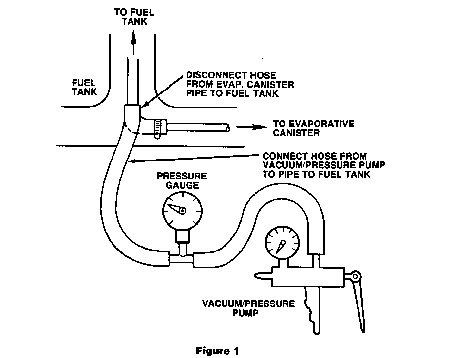
4. Disconnect fuel tank-to-evaporative canister line at hose connection located at left-hand (driver) side of vehicle at floor/sill area forward of fuel tank (See Figure 1).
5. Connect hand operated vacuum/pressure pump to evaporative canister line to fuel tank (See Figure 1) and apply between 1 and 1-1/2 P.S.I. pressure to this line.
Notice: Depending upon amount of fuel in fuel tank, varying lengths of time will occur before 1 P.S.I. threshold pressure will be obtained. The less fuel in the tank, the longer the time to reach the desired pressure. Under some circumstances, such as a large leak in the system, it will not be possible to raise the pressure to the 1 P.S.I. level (See Step 7).
6. Upon reaching a pressure between 1 and 1-1/2 P.S.I., cease pumping and check to see that pressure in system is maintained by noting initial gauge reading (1 to 1-1/2 P.S.I.), wait 2 minutes, note gauge reading again.
7. In the event of an inability to obtain a 1 P.S.I. pressure reading or inability to maintain pressure, apply liquid soap or equivalent to all connections between vacuum/pressure pump and fuel filler cap. Applying further pressure with hand pump (not exceeding 1-1/2 P.S.I.) visually inspect connections for leaks.
8. Repair leaks at connections by tightening hose clamps or replacing parts as necessary. Return to Step 5 and repeat leak check through Step 6.
9. If loss of pressure still occurs, recheck hose connections for a leak. Correct any remaining leaks at connections. If no leaks occur at connections and pressure loss still occurs, replace fuel filler neck (see Parts Information for correct filler neck P/N, based on body style) by following Fuel Filler Neck Replacement Procedure detailed below.
10. If no pressure loss is observed, fuel filler neck does not require replacement. Disconnect vacuum/pressure pump from vehicle and reconnect fuel tank-to-evaporative canister hose and reconnect negative battery cable.
11. Install Campaign Identification Label.
Fuel Filler Neck Replacement Procedure
12. Lower vehicle on hoist. If fuel level indicated on gauge is more than 5/8 full, remove fuel to that level.
When removing fuel:
- Have a dry chemical (Class B) fire extinguisher near the work area.
- Use a hand operated pump device to drain fuel to appropriate level. Save in a clean container for reuse.
CAUTION:
Never drain or store gasoline in an open container due to the possibility of fire or explosion.
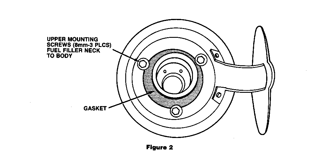
13. Remove fuel filler cap and remove three (3) screws - fuel filler neck to body (See Figure 2).
14. Raise vehicle on hoist.
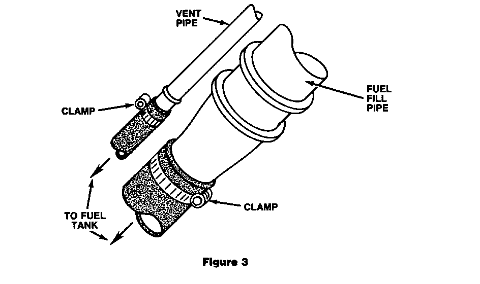
15. Release clamps at fuel filler hose to fuel filler neck and fuel tank vent hose to fuel filler neck (See Figure 3).
16. Disconnect two hoses from fuel filler neck.
Notice: Some residual fuel may be present in fuel filler neck/hose and will drain out as larger of two hoses is disconnected.
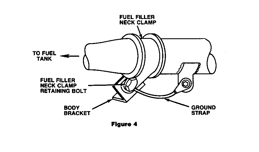
17. Disconnect electrical ground wire from fuel filler neck assembly (See Figure 4).
18. Remove fuel filler neck clamp retaining bolt (See Figure 4).
19. Remove fuel filler neck cover panel located in rear right-hand (passenger side) wheelhouse and retained by four (4) nuts.
20. Remove fuel filler neck assembly from vehicle.
21. Remove fuel filler neck clamp and gasket from fuel filler neck assembly. These parts are to be reused with new fuel filler neck assembly.
22. Install gasket and clamp to replacement fuel filler neck.
23. Install replacement fuel filler neck following above removal procedure in reverse order.
24. Reconnect negative battery cable.
25. Install Campaign Identification Label.
Installation Torque Specifications As Follows:
Step
18 Fuel Filler Neck Clamp Retaining Bolt - 12.5 N.m (9.2 lb. ft.)
15 Hose Clamps - Fuel Filler Neck (2) - 2.5 N.m (1.8 lb. ft.)
13 Screw - Fuel Filler Neck To Body (3) - 4.0 N.m (2.9 lb. ft. )
4 Hose Clamp - Fuel Tank To Evap. Canister - 2.5 N.m (1.8 lb. ft.)
INSTALLATION OF CAMPAIGN IDENTIFICATION LABEL
Clean surface of radiator upper mounting panel and apply a Campaign Identification Label. Make sure the correct campaign number is inserted on the label. This will indicate that the campaign has been completed.


General Motors bulletins are intended for use by professional technicians, not a "do-it-yourselfer". They are written to inform those technicians of conditions that may occur on some vehicles, or to provide information that could assist in the proper service of a vehicle. Properly trained technicians have the equipment, tools, safety instructions and know-how to do a job properly and safely. If a condition is described, do not assume that the bulletin applies to your vehicle, or that your vehicle will have that condition. See a General Motors dealer servicing your brand of General Motors vehicle for information on whether your vehicle may benefit from the information.
