MANUAL UPDATE-SEC.6D3 CHARGING SYSTEM (LEMANS GENERATORS)

Models Affected: 1989 LEMANS
This bulletin cancels and supersedes Section 6D3 "CHARGING SYSTEM" in the 1989 Pontiac LeMans Service Manual. Please replace Section 6D3 with this bulletin.
SECTION 6D3 CHARGING SYSTEM
NOTICE: When fasteners are removed, always reinstall them at the same location from which they were removed. If a fastener needs to be replaced, use the correct part number fastener for that application. If the correct part number is not available, a fastener of equal size and strength (or stronger) may be used. Fasteners that are not reused, and those requiring thread locking compound, will be called out. The correct torque value must be used when installing fasteners that require them. If the above conditions are not followed, parts or system damage could result. CONTENTS
General Description 6D3-1 Generator-1.6L Engines 6D3-4 Charging System--CS 6D3-1 Generator-2.0L Engines 6D3-4 Charging System--Bosch 6D3-1 GIB Module 6D3-4 Generator Invertering Buffer Specifications 6D3-7 (GIB) Module 6D3-1 Fastener Torques 6D3-7 Diagnosis 6D3-1 Generator Specifications 6D3-7 Charging System--CS and Bosch 6D3-1 Special Tools 6D3-7 On-Vehicle Service 6D3-4
GENERAL DESCRIPTION
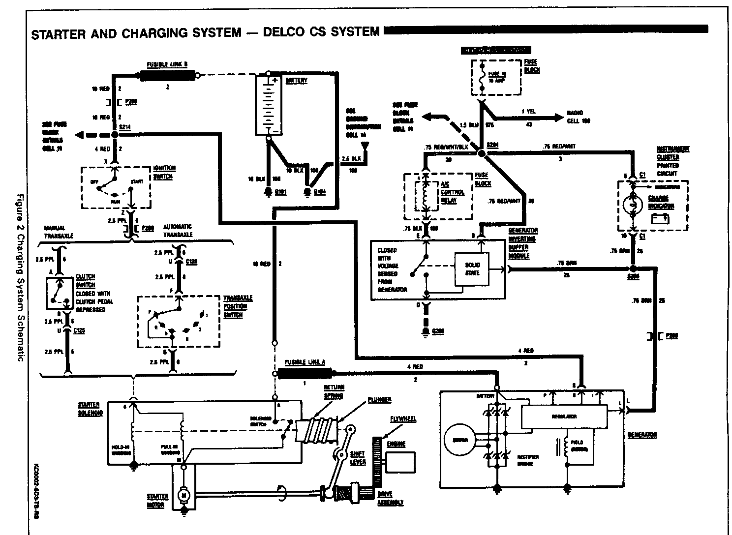
CHARGING SYSTEM-CS
The Delco Remy CS charging system has several models available, including the CS-121 and CS-130. The number denotes the OD in millimeters of the stator laminations.
CS Generators are equipped with internal regulators. A Delta stator, rectifier bridge, and rotor with slip rings and brushes are electrically similar to earlier generators. A conventional pulley and fan are used; there is no test hole.
Unlike three-wire generators, the CS-121 may be used with only two connections--battery positive (+) and an "L" terminal to the charge indicator lamp. Use of the "P," "I" and "S" terminals is optional. The "P" terminal is connected to the stator and may be connected externally to a tachometer or other device.
As with other charging systems, the charge indicator lamp lights when the ignition switch is turned to "RUN" and goes out when the engine is running. If the charge indicator is on with the engine running, a charging system defect is indicated. This indicator light will glow at full brilliance for several kinds of defects as well as when the system voltage is too high or too low. The regulator voltage setting varies with temperature and limits system voltage by controlling rotor field current.
This regulator switches rotor field current on and off at a fixed frequency of about 400 Hertz. By varying the on-off time, correct average field current for proper system voltage control is obtained. At high speeds, the on-time may be 10% and the off-time 90%. At low speeds, with high electrical loads, on-off time may be 90% and 10%, respectively.
No periodic maintenance of the CS-121 generator is required.
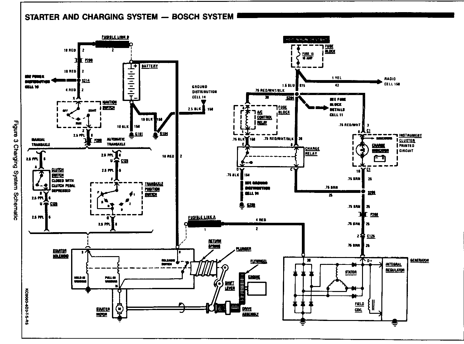
CHARGING SYSTEM-BOSCH
The German-made Bosch generators are similar in output to the Delco Remy generators. They share a common mounting configuration and both use intemal voltage regulators. The Bosch differs from the Delco in that it has a single-blade harness connector (as opposed to the 4-cavity connector on the Delco).
No periodic maintenance of the Bosch generator is required.
GENERATOR INVERTING BUFFER (GIB) MODULE
Some late production vehicles are equipped with a Generator Inverting Buffer (GIB) Module.
The GIB Module is located near the fuse box below the driver's-side instrument panel. It is housed in an aqua-green plastic box and taped to a support member.
The GIB module is connected in parallel to the charger indicator lamp. The basic purpose of the GIB module is to defeat the operation of the air conditioning and rear window defogger should generator output drop below a certain level. It performs this function by opening the ground to the A/C Control relay coil. This conserves generated power for more essential vehicle systems.
DIAGNOSIS
CHARGING SYSTEM-CS AND BOSCH
When operating normally, the generator indicator lamp will come on when the ignition switch is in the "RUN" position and go out when the engine starts. If the lamp operates abnormally, or if an undercharged or overcharged battery condition occurs, the following procedure may be used to diagnose the charging system. Remember that an undercharged battery is often caused by accessories being left on overnight or by a defective switch which allows a lamp, such as a trunk or glove box lamp, to stay on.
Diagnose the CS-121 generator with the following procedure:
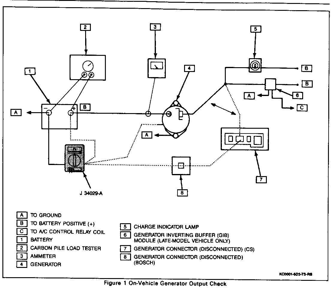
Figure 1 Tool Required: J 34029-A Digital Multimeter
1. Visually check the belt and wiring.
2. With the ignition switch in the "RUN" position and the engine stopped, the charge indicator lamp should be on. If not, detach the harness at the generator and ground the "L" terminal in the harness with a fused (5 amp) jumper lead
A. If the lamp lights, replace the generator.
B. If the lamp does not light, locate the open circuit between the ignition switch and the harness connector. The indicator lamp bulb may be burned out.
3. With the ignition switch in the "RUN" position and the engine running at moderate speed, the charge indicator lamp should be off. If not, detach the wiring harness at the generator.
A. If the lamp goes off, replace the generator.
B. If the lamp stays on, check for a short to ground in the harness between the connector and the indicator lamp or in the GIB module circuit.
Important
Always check the generator for output as described in Step 4 before assuming that a grounded "L" terminal circuit has damaged the regulator.
4. Check the battery for an overcharged or undercharged condition.
Important
For accurate results, this step requires that the vehicle battery be fully charged. Refer to BATTERY (SEC.6D1) for battery charging and testing procedures.
A. Attach a J 34029-A digital multimeter, an ammeter, and a carbon pile load to the vehicle. Be sure that the carbon pile load is tumed off (Figure 1).
B. With the ignition switch in the "OFF" position, check and record battery voltage.
C. Remove the harness connector from the generator.
D. Turn the ignition switch to the "RUN" position (engine not running), use a J 34029-A digital multimeter to check for voltage in the harness connector "L" terminal. Reading should be near battery voltage. If not, check the indicator "L" terminal circuits (including the GIB module) for open or grounded circuits causing voltage loss. Correct as necessary.
E. Re-attach the generator harness connector.
F. Run the engine at a moderate idle and measure the voltage across the battery terminals. The reading should be above that recorded in step (B), but less than 16 volts. If it is over 16 volts or below previous reading, replace the generator.
G. Run the engine at a moderate idle and measure the generator amperage output. Turn on the carbon pile load and adjust it to obtain maximum amps while maintaining battery voltage above 13 volts. If the reading is within 15 amps of the generator's rating, the generator is good. If the reading is more than 15 amps below specification, replace the generator. Refer to "Specifications" at the end of this section for rated generator output.
H. With the generator operating at maximum output, measure the voltage between the generator housing and the battery negative (-) terminal. The voltage drop should be P.5 volt or less. If the voltage drop is more than 0.5 volt, check the ground path from the generator housing to the battery negative (-) terminal to determine the cause of the voltage drop. Clean and tighten all ground connections.
Diagnose the Bosch generator with the following procedure:
Tool Required:
J 34029-A Digital Multimeter
1. Visually check the belt and wiring.
2. With the ignition switch in the "RUN" position and the engine stopped, the charge indicator lamp should be on. If not, detach the harness at the generator and ground the negative terminal in the harness with a fused (5 amp) jumper lead.
A. If the lamp lights, replace the generator.
B. If the lamp does not light, locate the open circuit between the ignition switch and the harness connector. The indicator lamp bulb may be burned out.
3. With the ignition switch in the "RUN" position and the engine running at moderate speed, the charge indicator lamp should be off. If not, detach the wiring harness at the generator.
A. If the lamp goes off, replace the generator.
B. If the lamp stays on, check for short to ground in the harness between the connector and indicator lamp.
4. Check the battery for an overcharged or undercharged condition.
Important
For accurate results, this step requires that the vehicle battery be fully charged. Refer to BATTERY (SEC.6D1) for battery charging and testing procedures.
A. Attach a J 34029-A digital multimeter, an ammeter, and a carbon pile load to the vehicle. Be sure the carbon pile load is turned off.
B. With the ignition switch in the "OFF" position, check and record battery voltage.
C. Remove the harness connector from the generator.
D. Turn the ignition switch to the "RUN" position (engine not running); use a J 34029-A digital multimeter to check for voltage in the harness connector BRN wire. The reading should be near battery voltage. If not, check the charge indicator circuits for open or grounded circuits causing voltage loss. Correct as necessary.
E. Re-attach the generator harness connector.
F. Run engine at a moderate idle; check voltage across the battery terminals. The reading should be above that recorded in step (B), but less than 16 volts. If it is over 16 volts or below previous reading, replace generator.
G. Run the engine at a moderate idle; check the generator amperage output. Turn on the carbon pile load and adjust it to obtain maximum amperage while maintaining battery voltage above 13 volts. If the reading is within 15 amps of the generator's rating, the generator is good. If the reading is more than 15 amps below specification, replace the generator. Refer to "Specifications" at the end of this section for rated generator output.
H. With the generator operating at maximum output, measure the voltage between the generator housing and the battery negative (-) terminal. Voltage drop should be 0.5 volt or less. If more than 0.5 volt, check ground path from generator housing to battery negative (-) terminal to determine the cause of voltage drop. Clean and tighten all ground connections.
ON-VEHICLE SERVICE
Generator-1.6L Engines
Remove or Disconnect
1. Battery negative (-) cable. Loosen 2 mounting bolts.
2. Drive belt.
3. Electrical connections.
4. Two mounting bolts and the generator.
Install or Connect
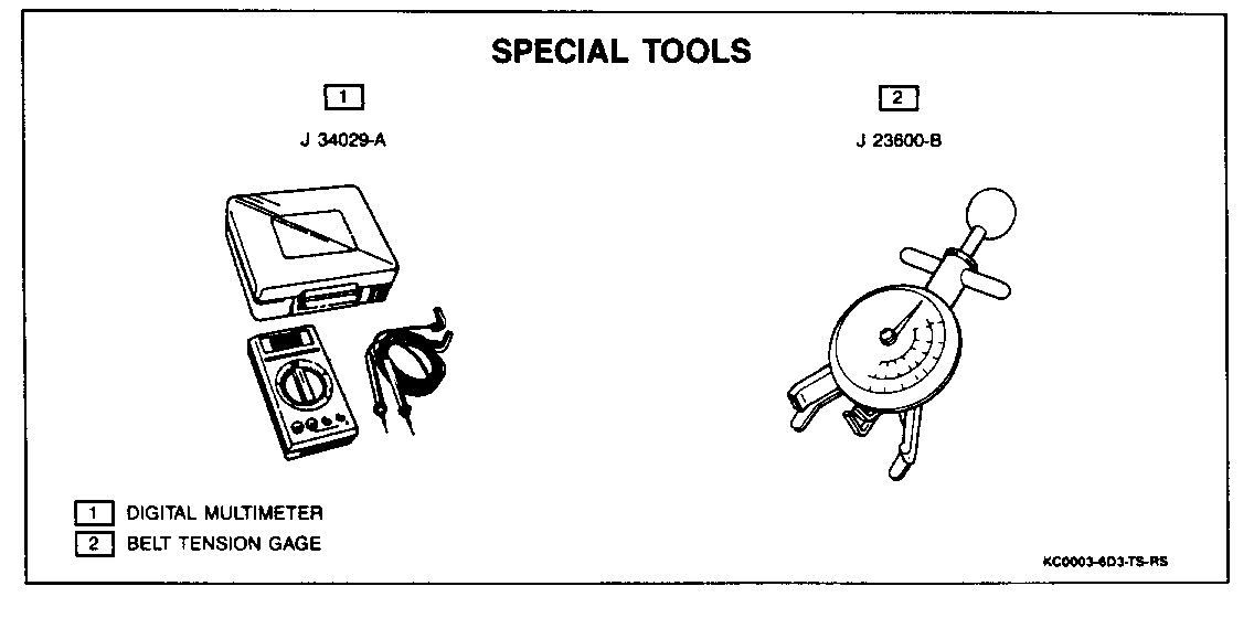
Tool Required:
J 23600-B Belt Tensioner Gage
1. Electrical connections to the generator.
2. Generator to the vehicle.
3. Lower pivot bolt; do not tighten fully.
4. Upper bolt; do not tighten fully.
5. Drive belt to the pulley and attach a J 23600-B belt tensioner gage.
Adjust
Using a pry bar to push the generator away from the engine, adjust the belt tension to:
400 N (90 lbs.) for a new belt. 350 N (77 lbs.) for a used belt.
NOTICE: When using a pry bar to set the drive belt tension, always apply pressure to the middle of the generator casing. Application of pressure at either end of the generator could damage the unit (Bosch generator only).
The CS generator has a boss near the drive end of the unit for attaching a wrench. Pull on this wrench to set belt tension on CS generator systems.
Tighten
Lower pivot bolt to 51 N-m (38 lb.ft.).
Upper bolt to Z7 N-m (20 lb. ft.).
6. Battery negative (-) cable.
Generator -2.0L Engines
Remove or Disconnect
1. Battery negative (-) cable.
2. Serpentine drive belt from generator. Push down on the tensioner pulley and lift the belt from the generator pulley.
3. Harness connector.
4. Three mounting bolts and the generator.
5. Single red wire from the back of the generator.
Rinstall or Connect
1. Wire to the back of the generator.
2. Generator to the vehicle.
3. Three mounting bolts.
Tighten
Lower bolt to 51 N - m (3 8 lb. ft.). Upper bolt to 27 N - m (20 lb. ft.). Rear mounting bolt to 33 N-m (24 lb.ft.).
4. Harness connector.
5. Drive belt.
6. Battery negative (-) cable.
Generator Inverting Buffer (GIB) Module
Remove or Disconnect
1. Electrical tape securing GIB module to support member.
2. Printed circuit from within plastic housing; open one end of housing and slide circuit out.
Install or Connect
1. A new GIB circuit board into plastic housing.
2. GIB module to original position with electrical tape.
SPECIFICATIONS
FASTENER TORQUES
CS-121
Upper Bolt 27 N-m (20 lb.ft.) Lower Pivot Bolt 51 N-m (38 lb.ft.) Rear Mounting Bolt 33 N-m (24 lb.ft.)
Bosch
Lower Pivot Bolt 51 N-m (38 lb.ft.) Upper Bolt 27 N-m (20 lb.ft.)
GENERATOR SPECIFICATIONS Engine Equipment Gen/Mod Amp ------ --------- ------- --- 1.6L NON-A/C 90244847/Bosch 55 1.6L NON-A/C 90244848/Bosch 65 1.6L NON-A/C 1101564/CS-121 60 1.6L A/C 90244848/Bosch 65 1.6L A/C 1101531/CS-121 72 1.6L A/C 1101563/CS-121 72 2.0L All 1101565/CS-121 72


General Motors bulletins are intended for use by professional technicians, not a "do-it-yourselfer". They are written to inform those technicians of conditions that may occur on some vehicles, or to provide information that could assist in the proper service of a vehicle. Properly trained technicians have the equipment, tools, safety instructions and know-how to do a job properly and safely. If a condition is described, do not assume that the bulletin applies to your vehicle, or that your vehicle will have that condition. See a General Motors dealer servicing your brand of General Motors vehicle for information on whether your vehicle may benefit from the information.
