Tools Required
EN46567 (DW110-020-A) Engine Support Fixture
Removal Procedure
- Remove the air cleaner assembly. Refer to Air Cleaner Assembly Replacement for the 0.8L engine or Air Cleaner Assembly Replacement for the 1.0L engine.
- Remove the air cleaner assembly. Refer to Air Cleaner Assembly Replacement for the 0.8L engine or Air Cleaner Assembly Replacement for the 1.0L engine.
- Remove the battery and battery tray. Refer to Battery Replacement .
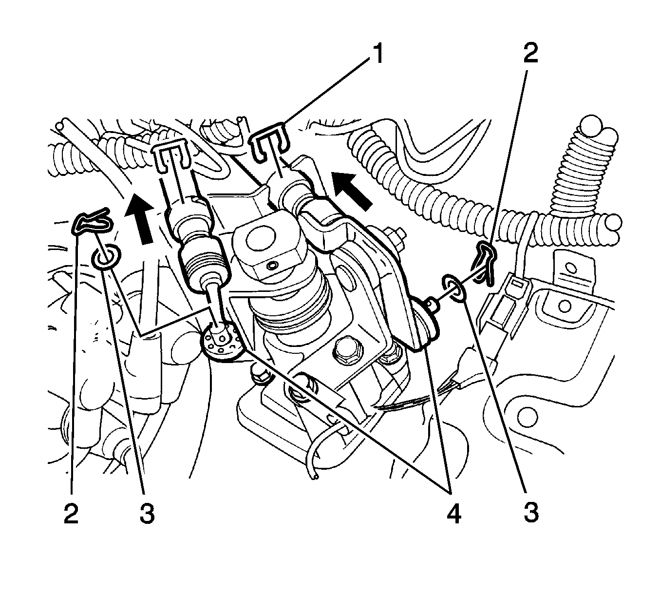
- Remove the select and shift cable pins (1) and remove the washers (2).
- Disconnect the select and shift cable (3).
- Remove the cable E-rings (4).
- Disconnect the cables from the cable bracket.
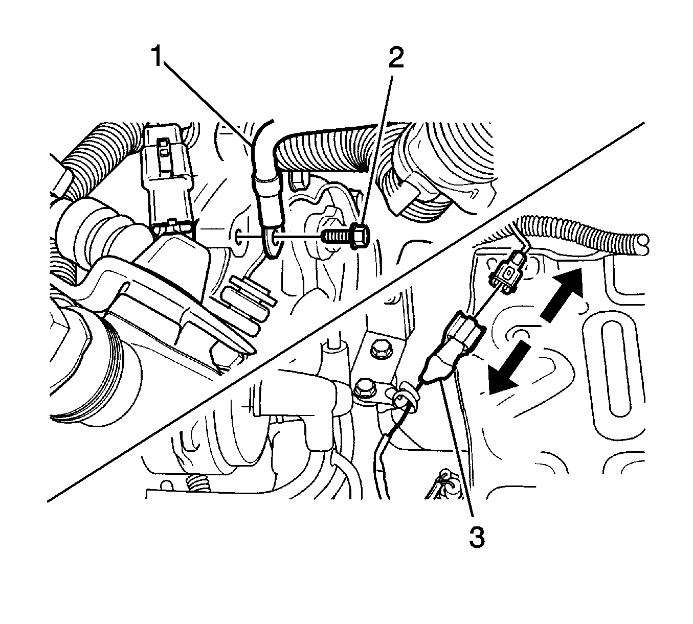
- Remove the bending strap from the engine wiring harness. Disconnect the ground wire and the backup lamp switch connector.
- Remove the ground wire bolt (2).
- Disconnect the ground wire (1).
- Disconnect the backup lamp switch connector (3).
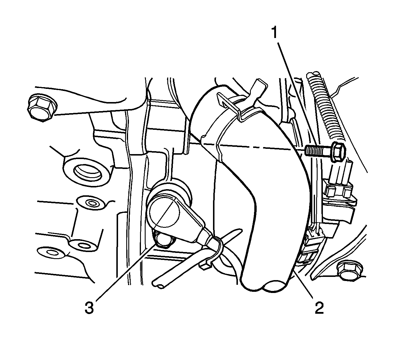
- Remove the bolts (1) and disconnect the radiator lower hose (2).
- Remove the bolt (3) and remove the crankshaft position (CKP) sensor.
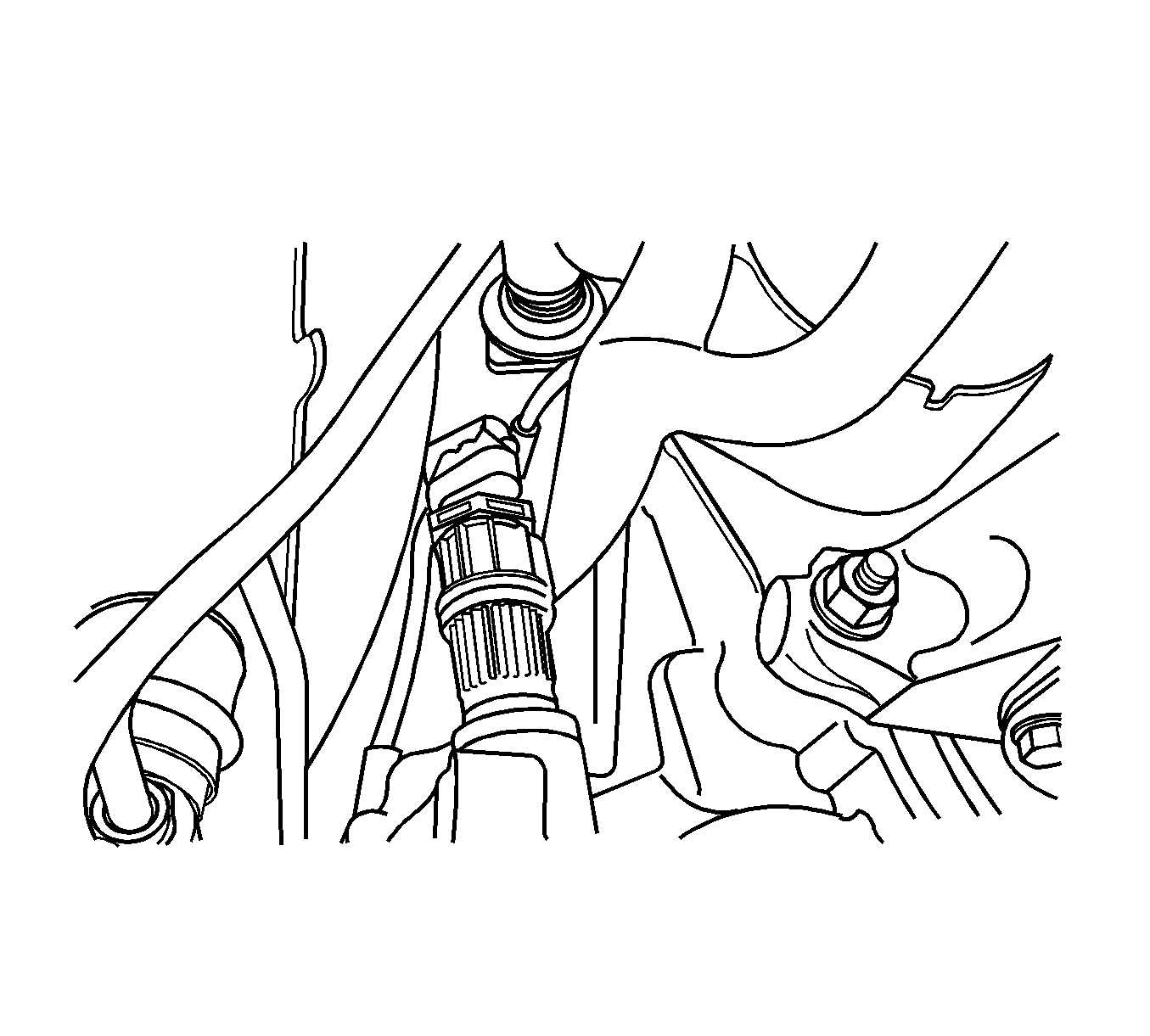
- Disconnect the vehicle speed sensor (VSS) connector.
- Remove the VSS.
- Remove the starter motor. Refer to Starter Motor Replacement .
- Remove the weatherstrip from the air inlet grille panel.
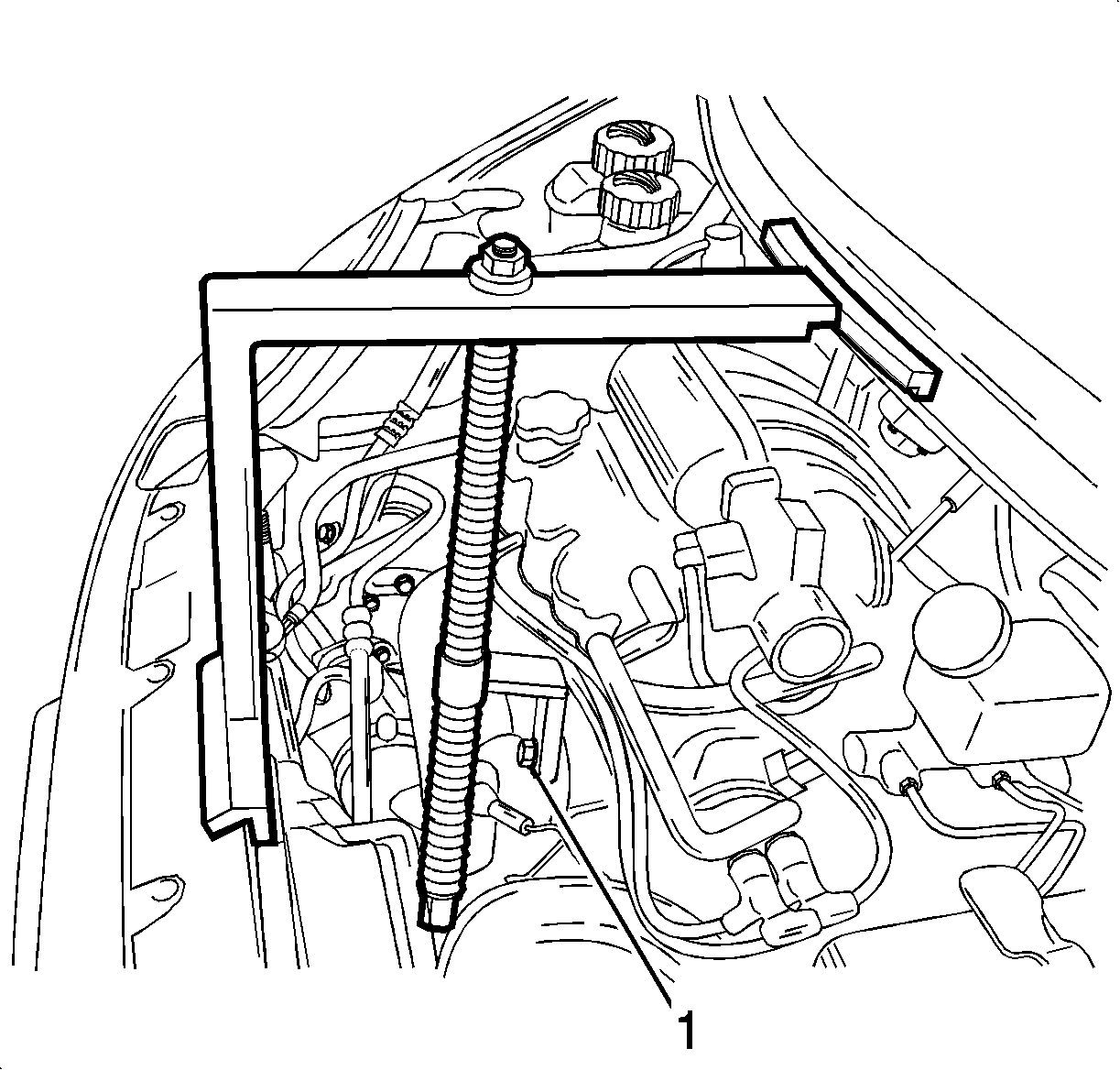
- Position EN46567 (1) on the air inlet grille panel and the front upper panel.
- Remove the exhaust manifold bolt. Tighten the engine fixture joint with a bolt.
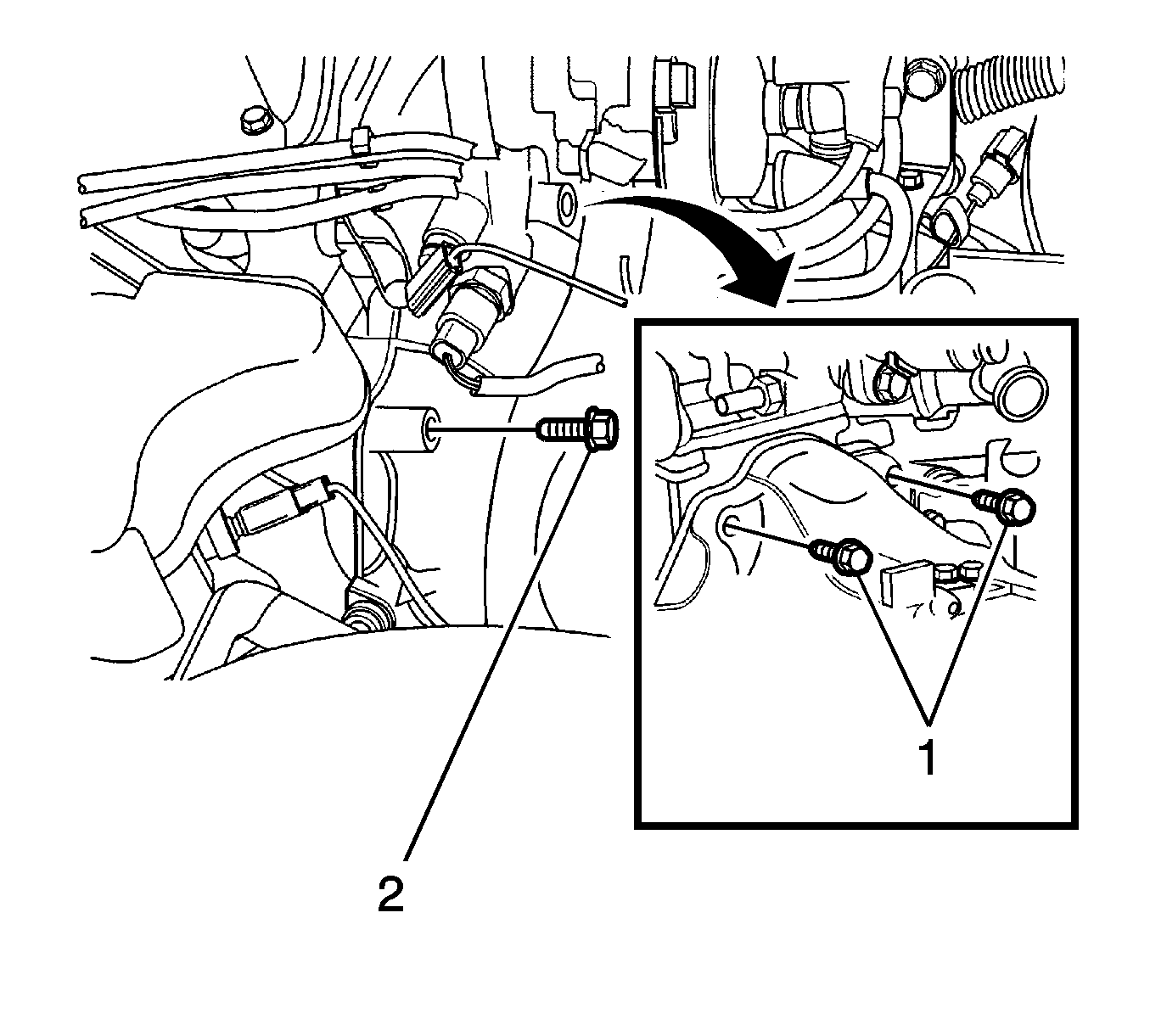
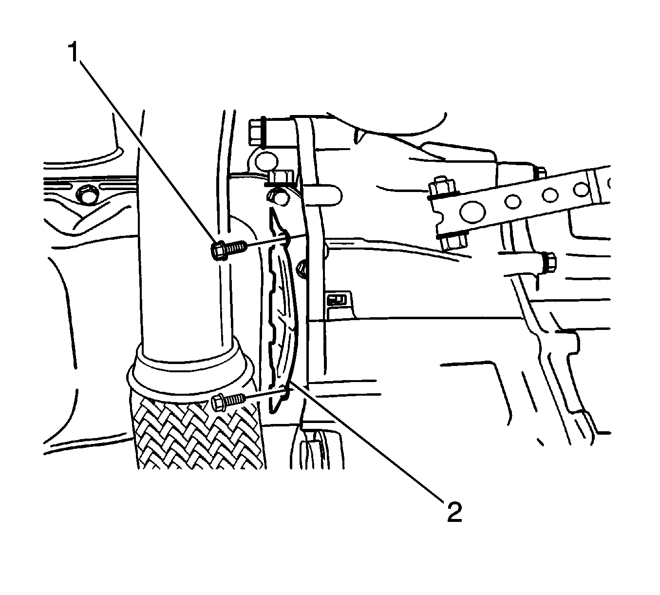
- Remove the side bolt (1) from the transaxle exhaust manifold and the side bolt (2) from the thermostat housing.
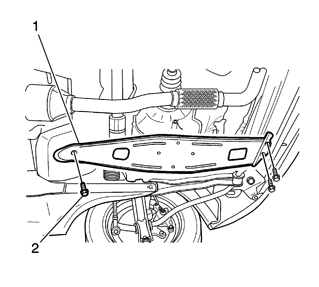
- Remove the transaxle under cover (2).
- Remove the front tire and wheel assemblies. Refer to Tire and Wheel Removal and Installation .
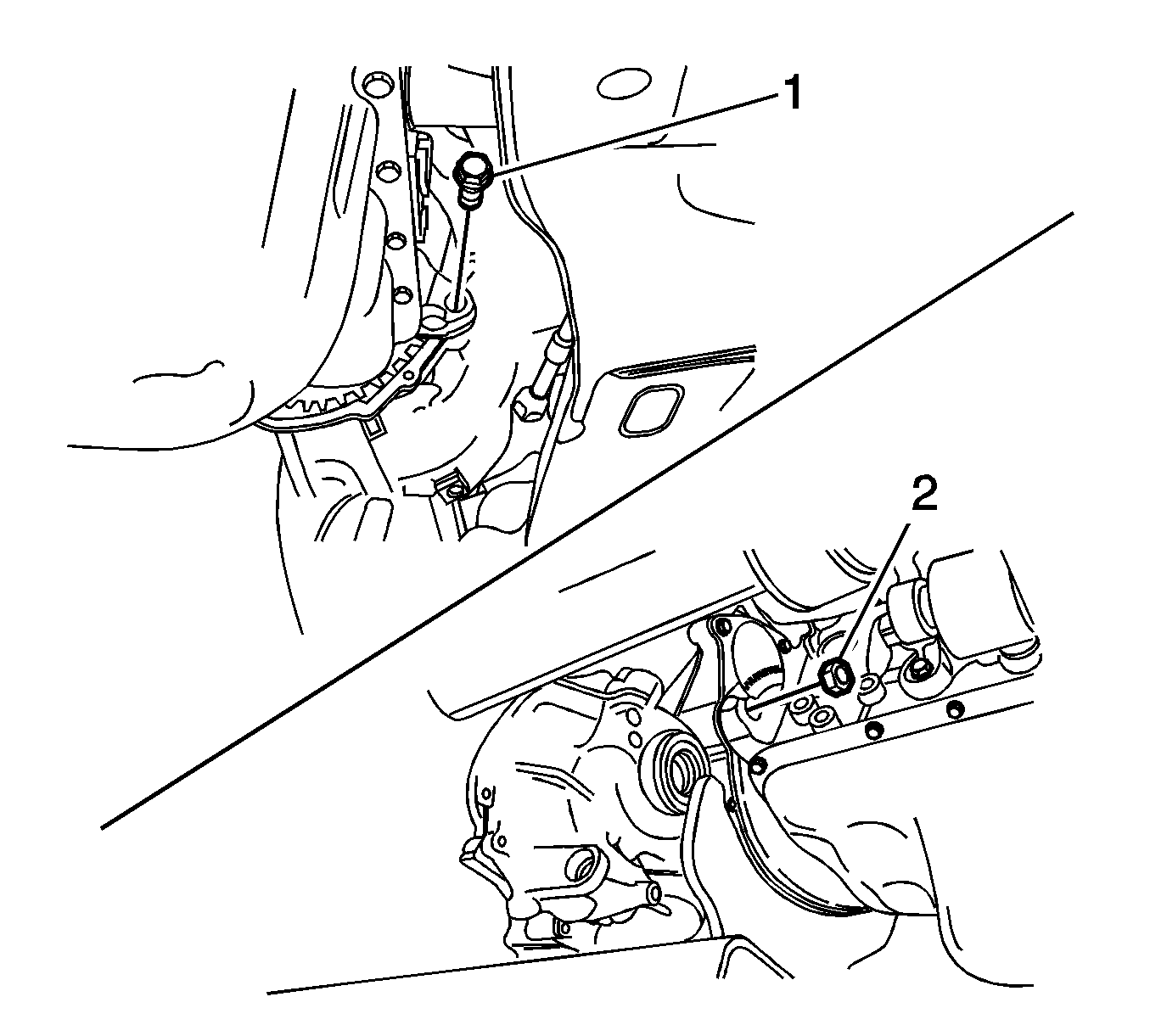
- Remove the drain plug. Drain the fluid.
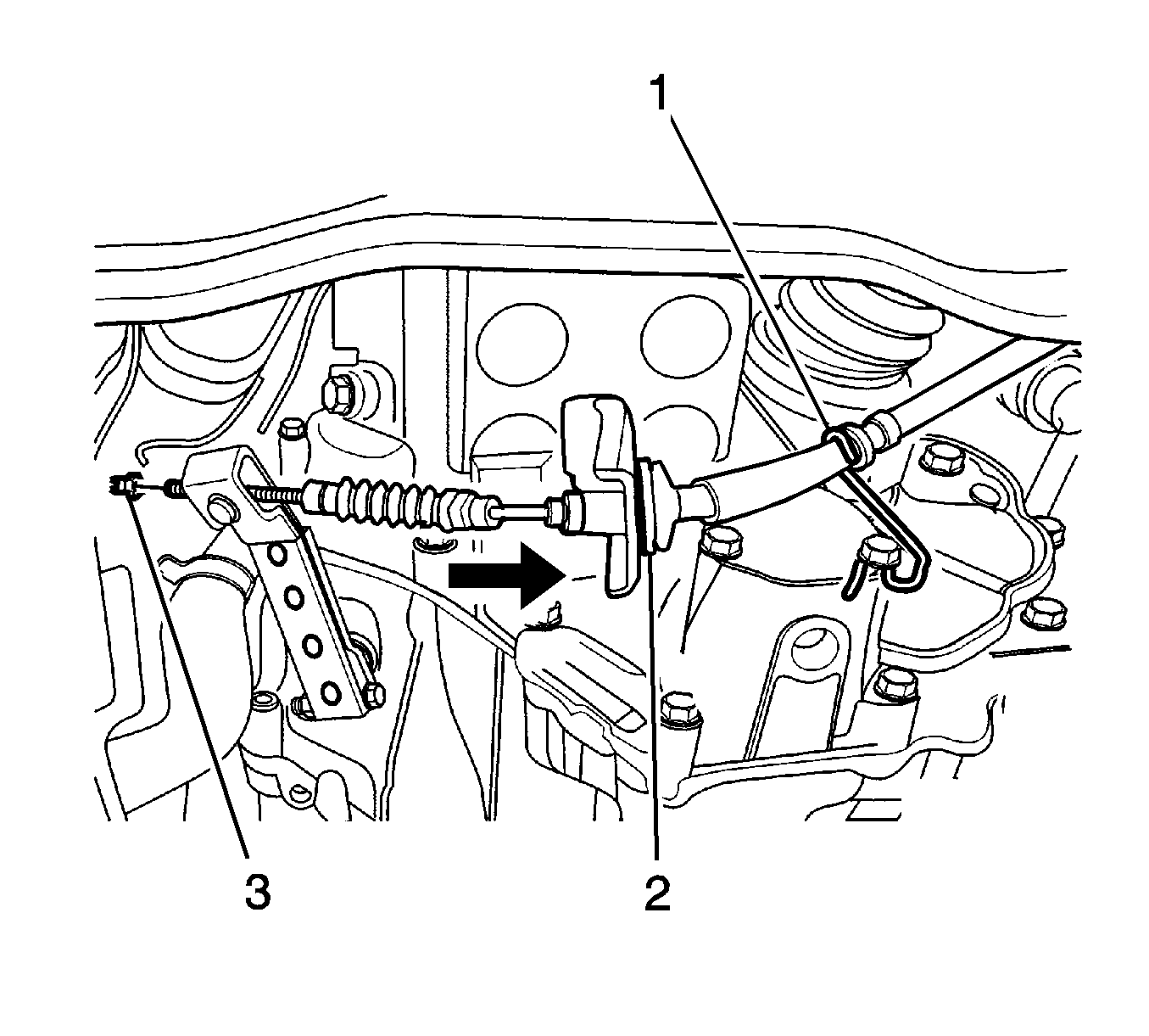
- Remove the clutch cable adjust nut (1).
- Disconnect the clutch cable from the transaxle mount hole (2).
- Remove the front under longitudinal frames and stabilizer. Refer to Stabilizer Shaft Replacement .
- Remove the drive axle from the transaxle side. Refer to Front Drive Axle Inner Shaft Replacement .
- Remove the bolts (1) from the clutch housing lower plate. Remove the lower plate (2).
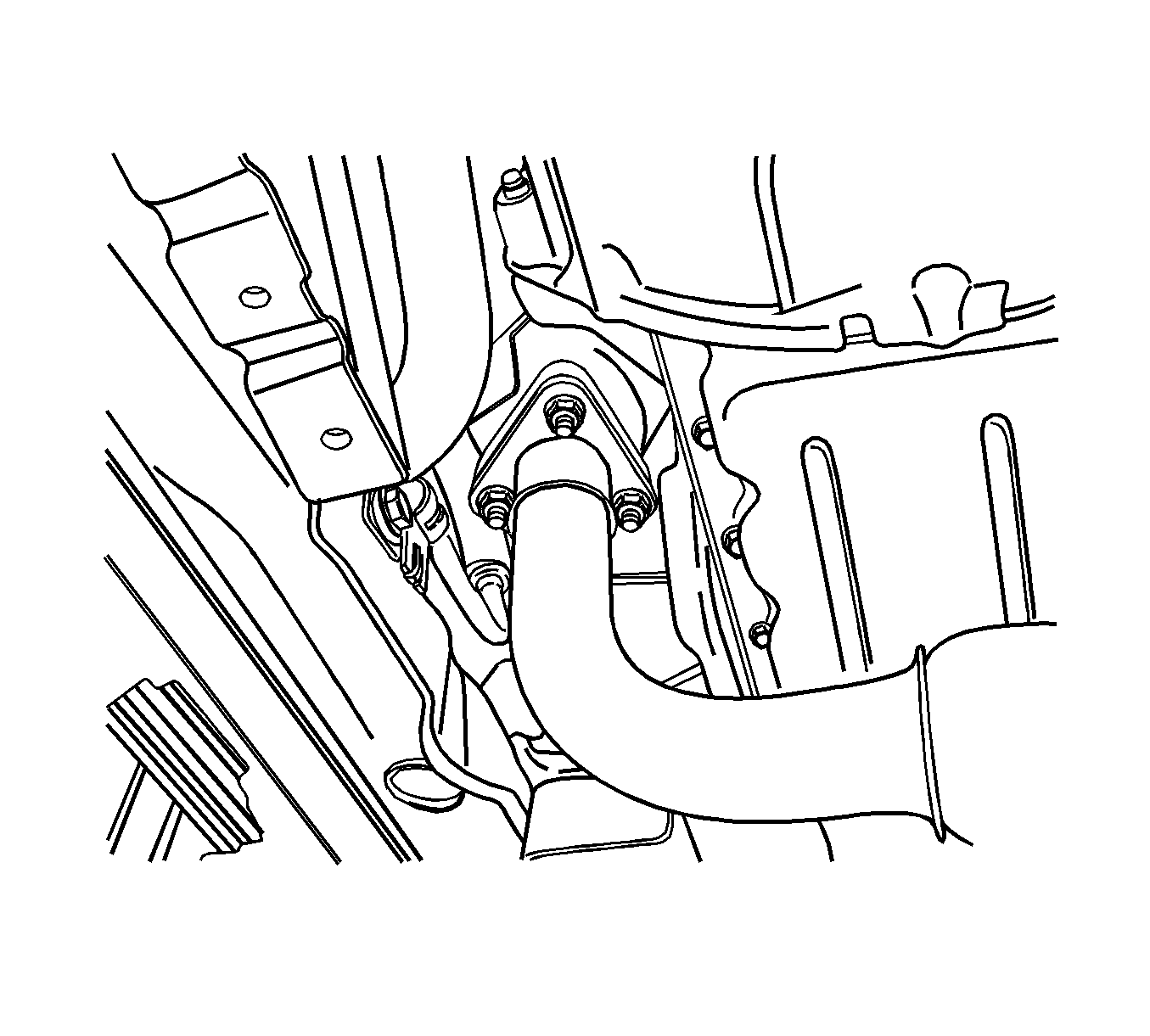
- Remove the front exhaust pipe nuts.
- Remove the gasket and separate the exhaust manifold pipe.
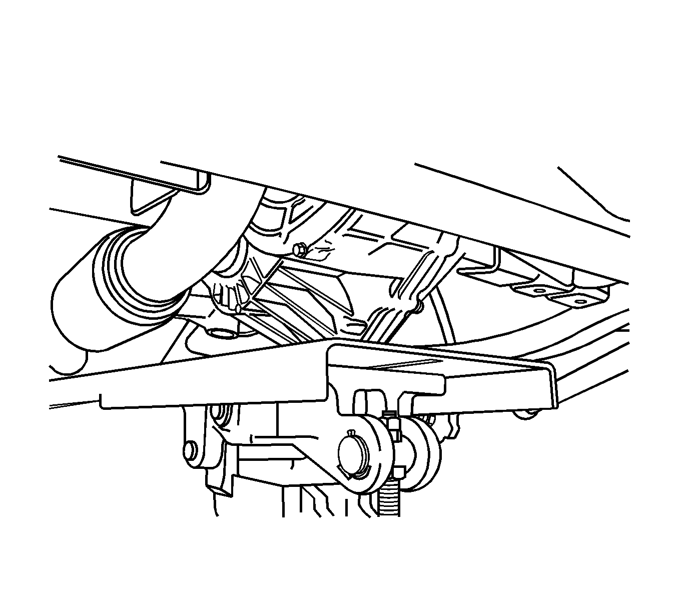
- Support the transaxle with a transaxle support jack.
- Remove the transaxle lower bolt (1) and nut (2).
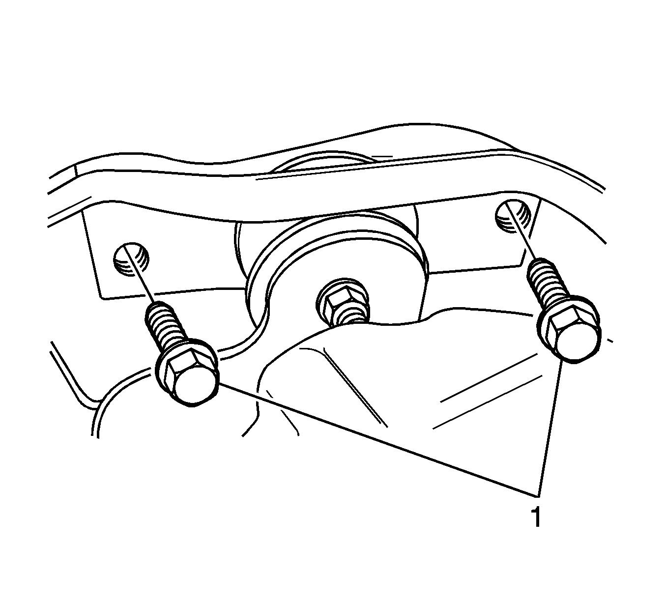
- Remove the transaxle mount bolts (1).
- Remove the transaxle.
- Slide the transaxle sideways, away from the engine block.
- Lower the transaxle.
Caution: Refer to Batteries Produce Explosive Gases Caution in the Preface section.
Caution: Refer to Hot Exhaust System Caution in the Preface section.
Caution: Refer to Hot Exhaust System Caution in the Preface section.

Installation Procedure
- Properly support the transaxle onto the transaxle support jack.
- Raise the transaxle into position.
- Install the transaxle mounting bolts (1).
- Install the transaxle lower bolt (1) and nut (2).
- Install the front exhaust pipe.
- Install the clutch housing lower plate (2).
- Install the drive axle. Refer to Front Drive Axle Inner Shaft Replacement .
- Install the front under longitudinal frames and stabilizer. Refer to Stabilizer Shaft Replacement .
- Connect the clutch cable (2).
- Install the front tire and wheel assemblies. Refer to Tire and Wheel Removal and Installation .
- Install the transaxle under cover (1).
- Install the transaxle upper bolts (1).
- Remove the engine fixture joint bolt (1) from the exhaust manifold and replace the bolt.
- Remove the engine support fixture.
- Install the air inlet grille panel weatherstrip.
- Install the starter motor. Refer to Starter Motor Replacement .
- Install the VSS, if equipped.
- Connect the speedometer cable.
- Install and connect the CKP sensor (3).
- Connect the radiator lower hose (2).
- Connect the backup lamp switch connector (3).
- Connect the ground wire (1) and install the bolt (2).
- Connect the select and the shift cable (4).
- Install the battery and the battery tray. Refer to Battery Replacement .
- Install the air cleaner assembly. Refer to Air Cleaner Assembly Replacement for the 0.8L engine or Air Cleaner Assembly Replacement for the 1.0L engine.
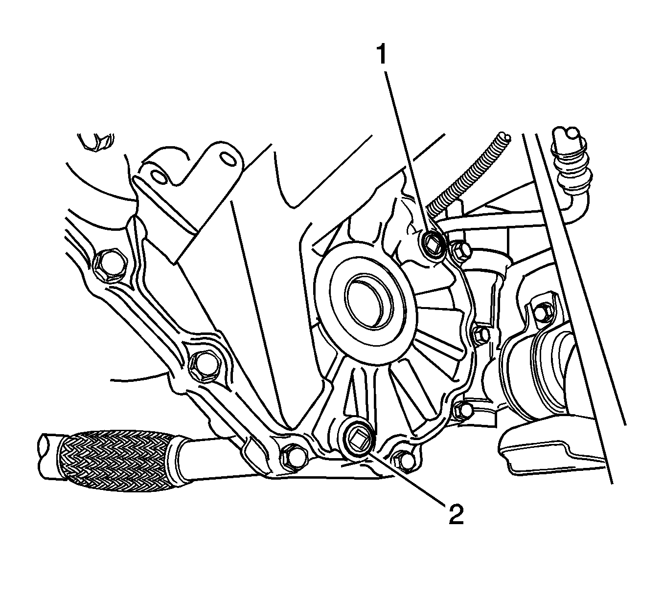
- Install the transaxle drain plug (2).
- Install the oil level plug (1).
- Refill with the recommended transaxle fluid to the proper level.
- Install the oil level plug.

Notice: Refer to Fastener Notice in the Preface section.

Tighten
Tighten the bolts on the body side to 45-55 N·m (33-41 lb ft).

Tighten
Tighten the bolt and nut to 55-65 N·m (41-48 lb ft).

Tighten
Tighten the nuts on the exhaust manifold side to 25-35 N·m (18-25 lb ft).


Tighten
Tighten the bolts to 35-55 N·m (25-41 lb ft).

Tighten
Tighten the bolts to 55-65 N·m (41-48 lb ft).


Tighten
Tighten the bolt to 5-8 N·m (44-70 lb in).
Tighten
Tighten the bolt to 8-15 N·m (70-132 lb in).


Tighten
Tighten the drain plug to 25-30 N·m (18-22 lb ft).
Specifications
| • | The Classification is 75W-85 (GL-4). |
| • | The Capacity is 2.1L (2.21 qt). |
Tighten
Tighten the plug to 25-30 N·m (18-22 lb ft).
