For 1990-2009 cars only
Tools Required
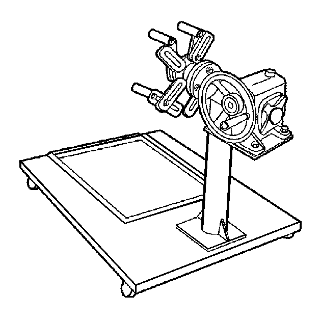
OTC 1726 (KM-412) Engine Overhaul Stand
Disassembly Procedure
- Remove the engine. Refer to Engine Replacement .
- Remove the transaxle from the engine. Refer to Transmission Replacement for the manual transmission.
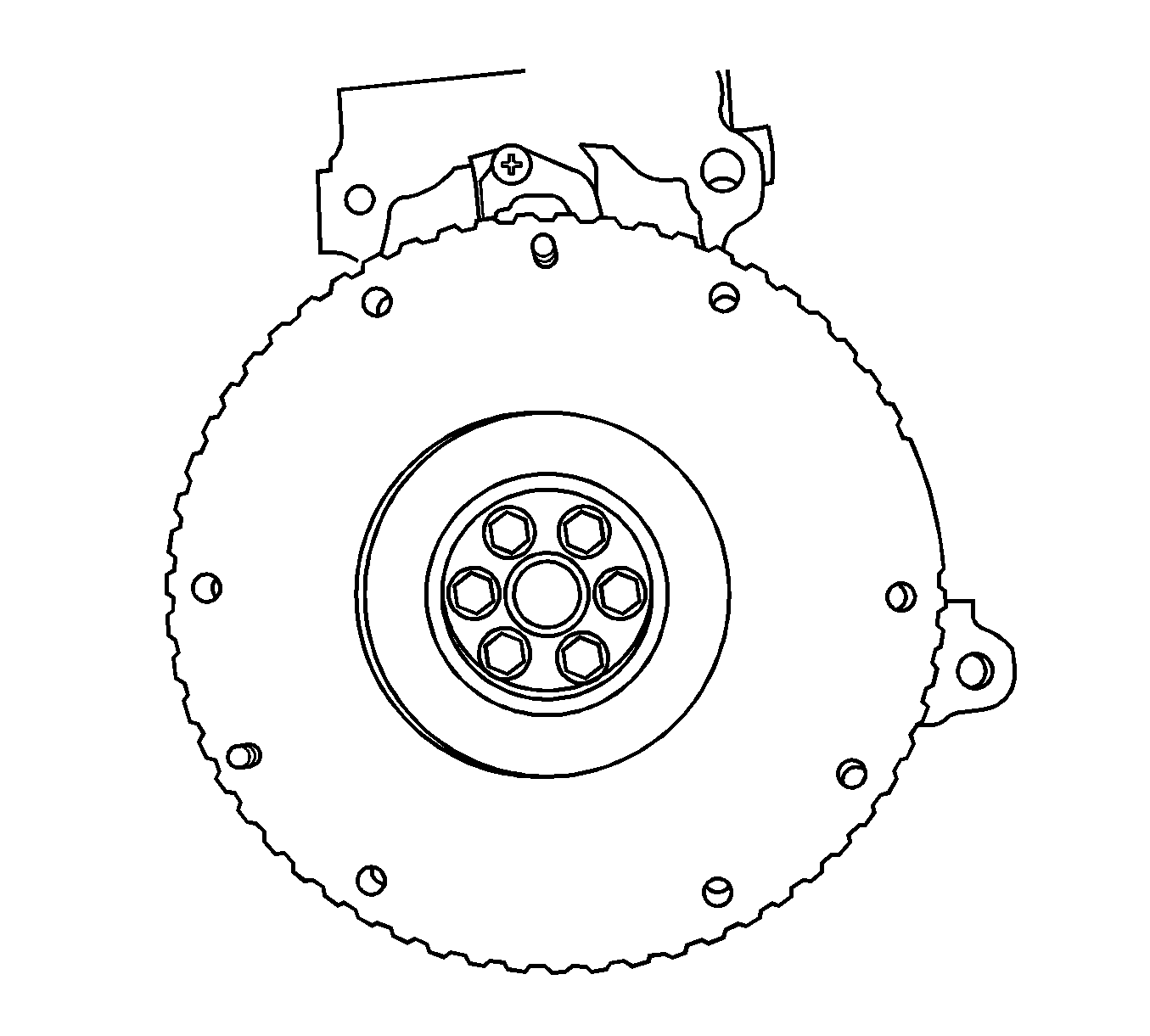
- Remove the flywheel bolts.
- Remove the flywheel.
- Mount the engine assembly on the OTC 1726 .
- Remove the cylinder head. Refer to Cylinder Head Replacement .
- Drain the engine oil from the engine.
- Remove the power steering adjusting bolts.
- Remove the power steering/air conditioning (A/C) belt.
- Turn the A/C compressor downward.
- Remove the A/C compressor/power steering bracket bolts.
- Remove the A/C compressor/power steering bracket.
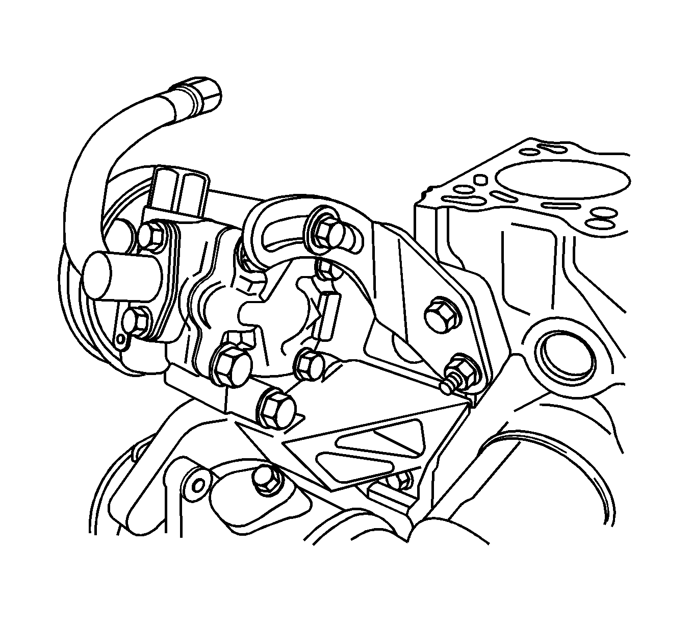
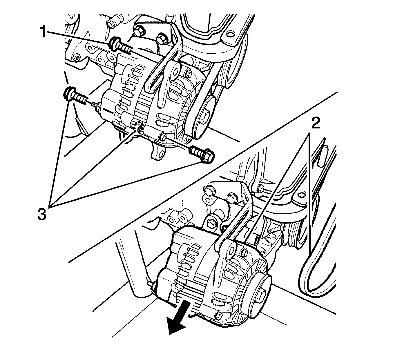
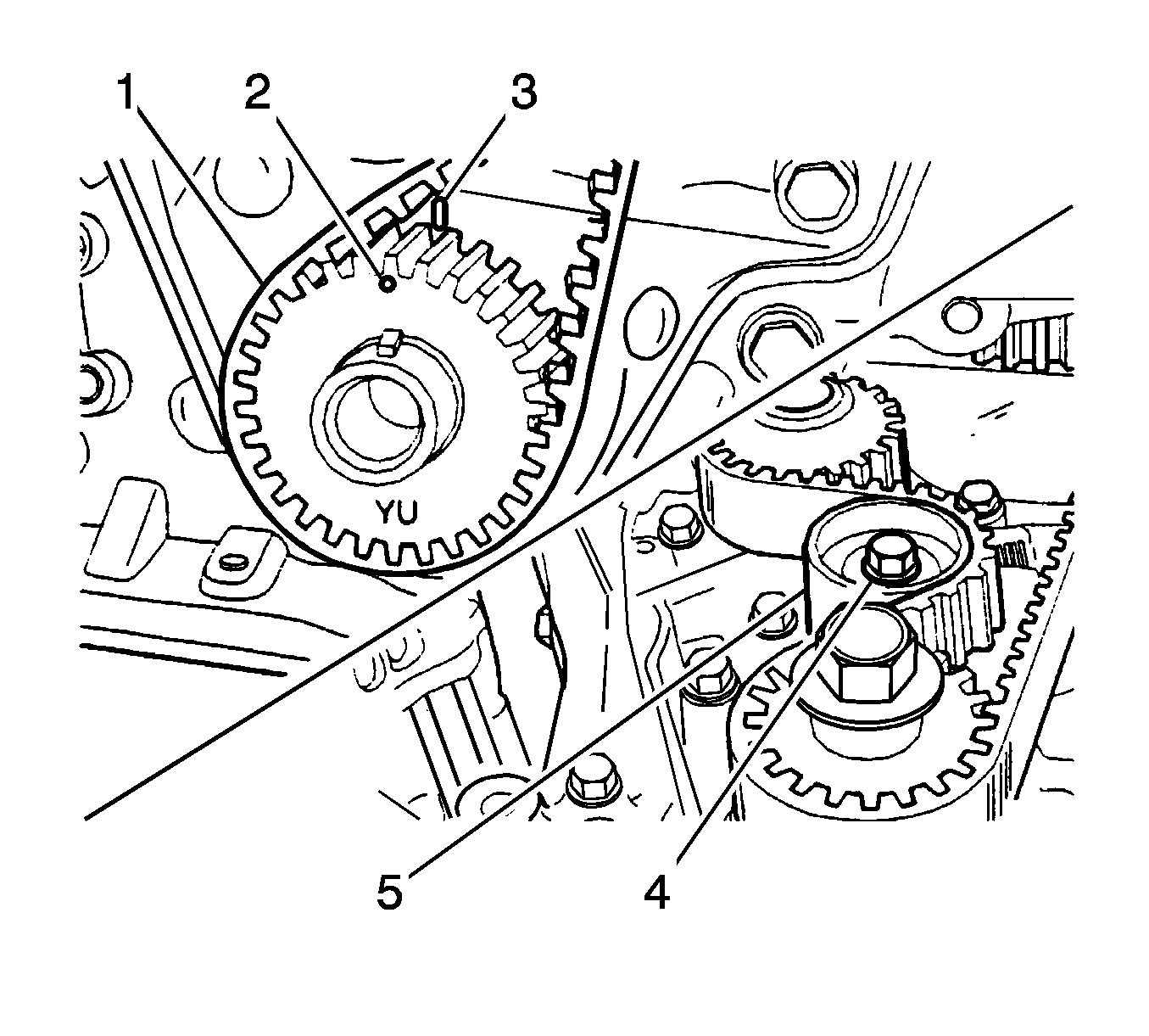
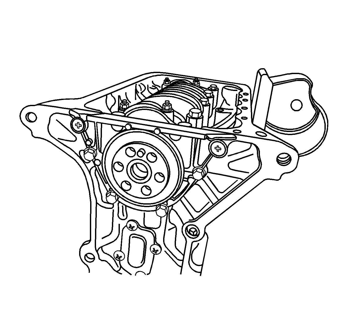
- Loosen the generator bolt (1).
- Loosen the generator lower bolts and the nut (3).
- Remove the generator and belt (2).
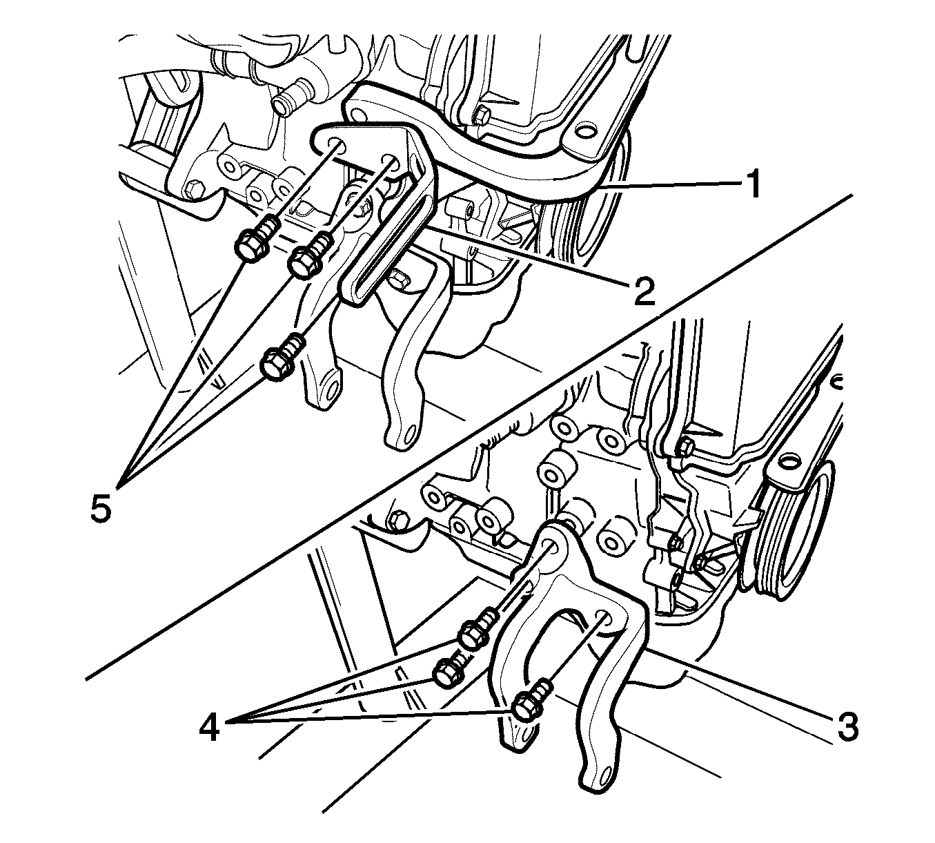
- Loosen the engine mount upper bracket bolts (5).
- Remove the generator shackle (2).
- Remove the upper bracket (1).
- Loosen the engine mount lower bracket bolts (4).
- Remove the lower bracket (3).
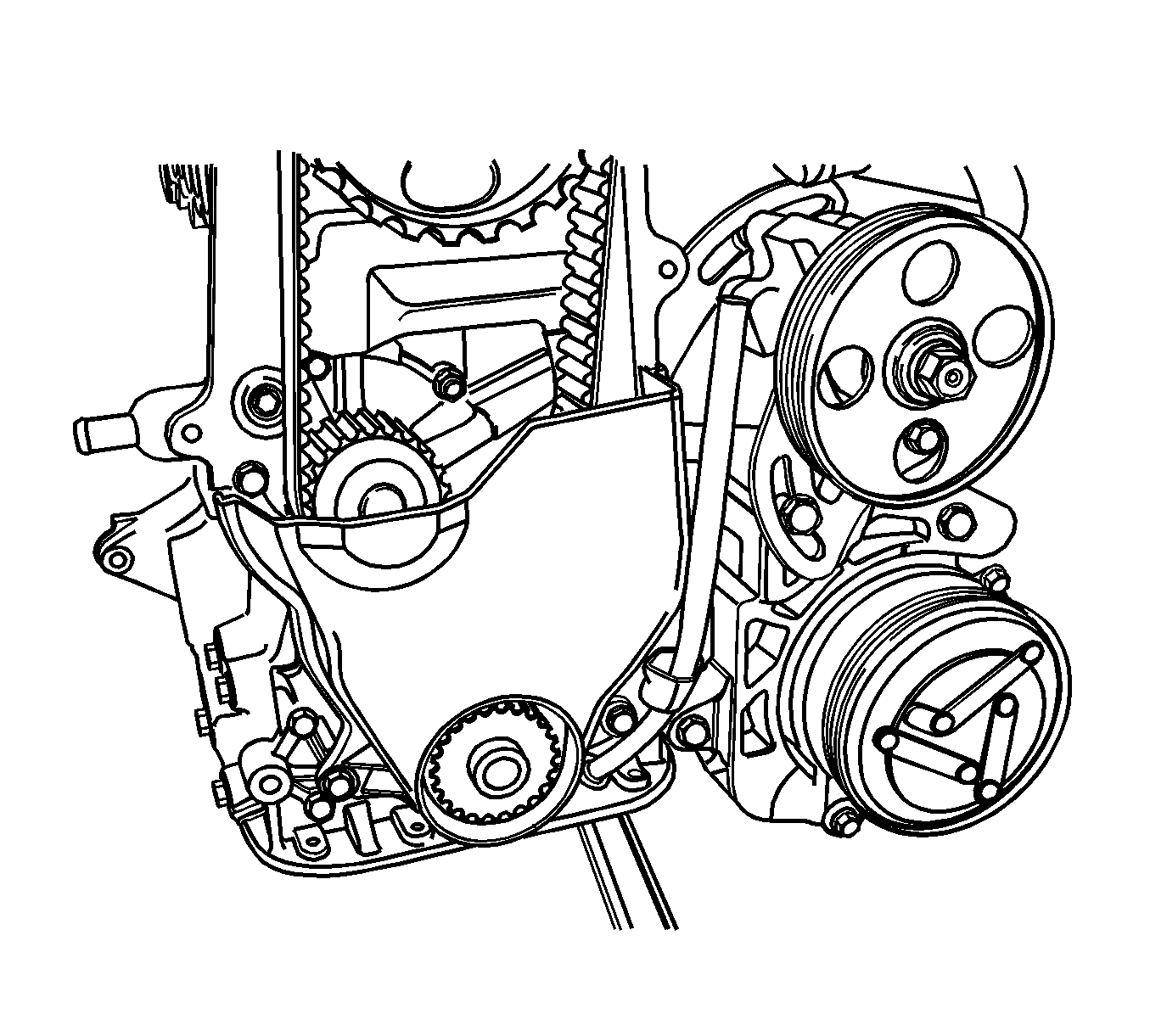
- Remove the upper timing belt cover bolts.
- Remove the upper timing belt cover.
- Remove the lower timing belt cover bolts.
- Remove the lower timing belt cover.
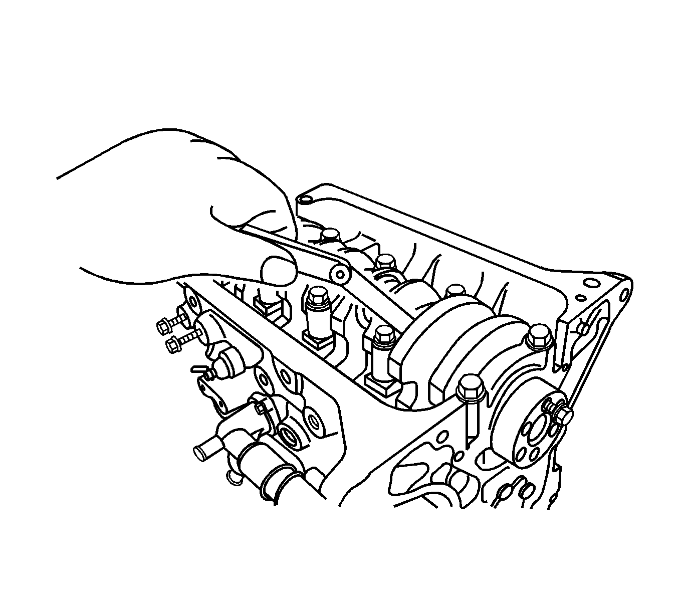
- Loosen the timing belt automatic tensioner (3) bolt.
- Remove the automatic tensioner from the timing belt (1).
- Remove the timing belt.
- Rotate the engine on the OTC 1726 .
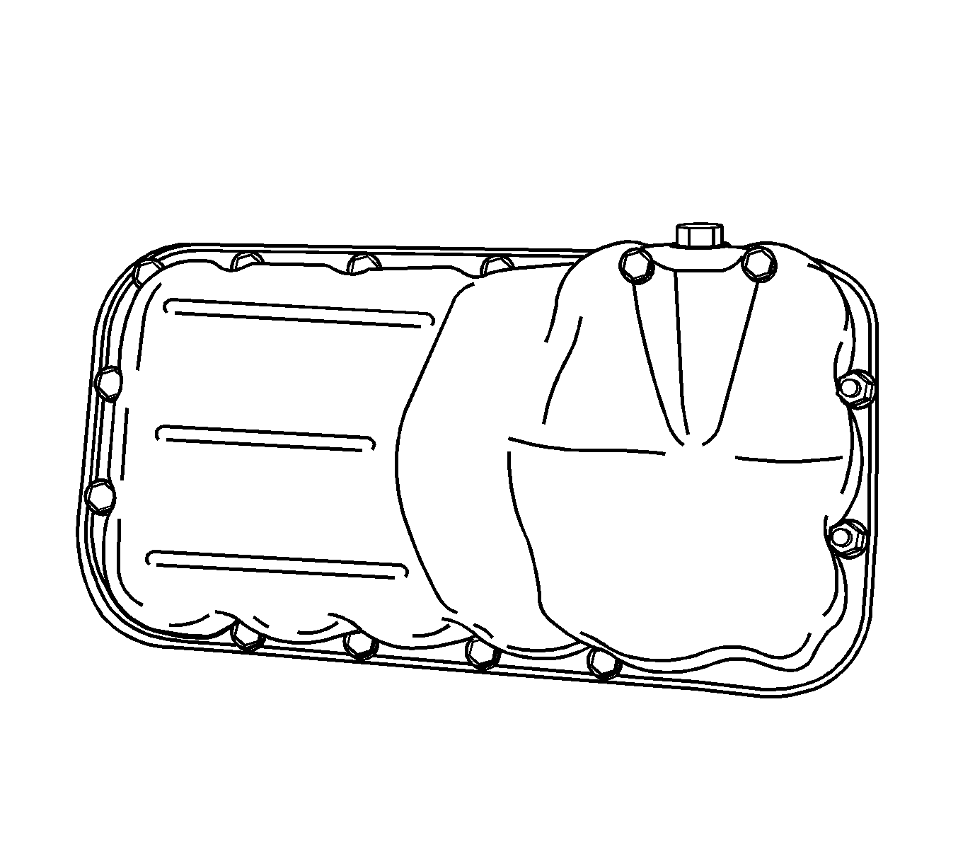
- Remove the oil pan retaining bolts and the nuts.
- Remove the oil pan.
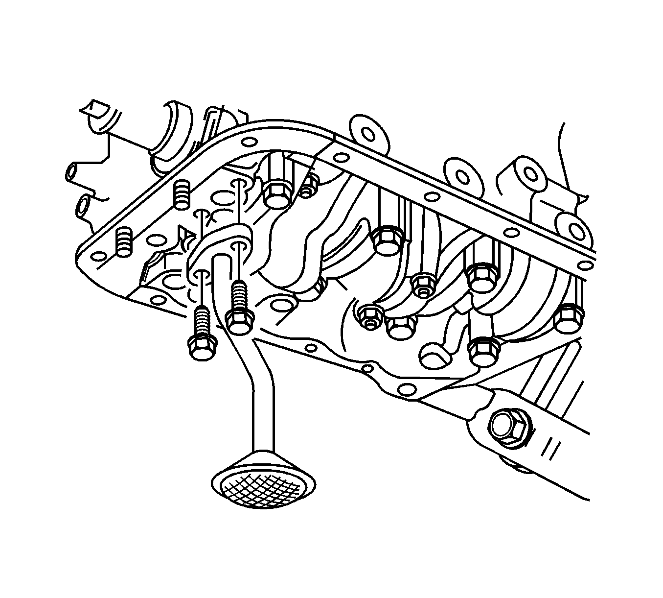
- Remove the oil pan pickup tube bolts.
- Remove the oil pan pickup tube.
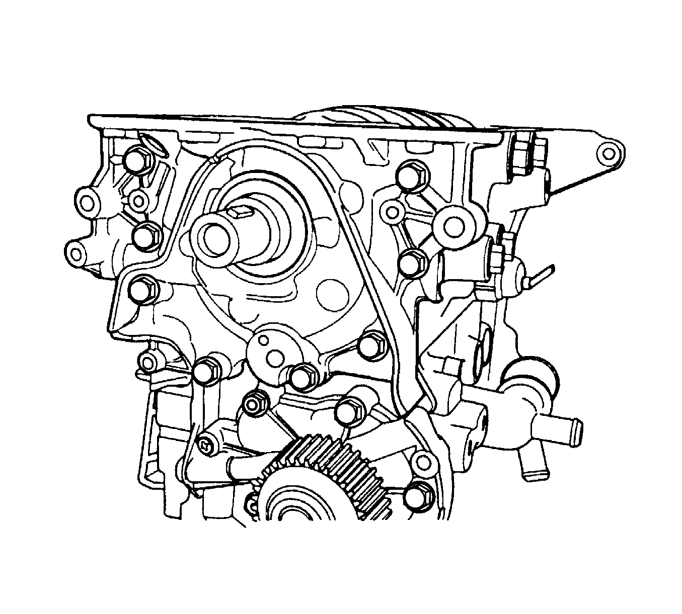
- Remove the oil pump retaining bolts.
- Remove the oil pump.
- Remove the crankshaft rear oil seal housing screws and bolts.
- Remove the gasket and the oil seal housing.
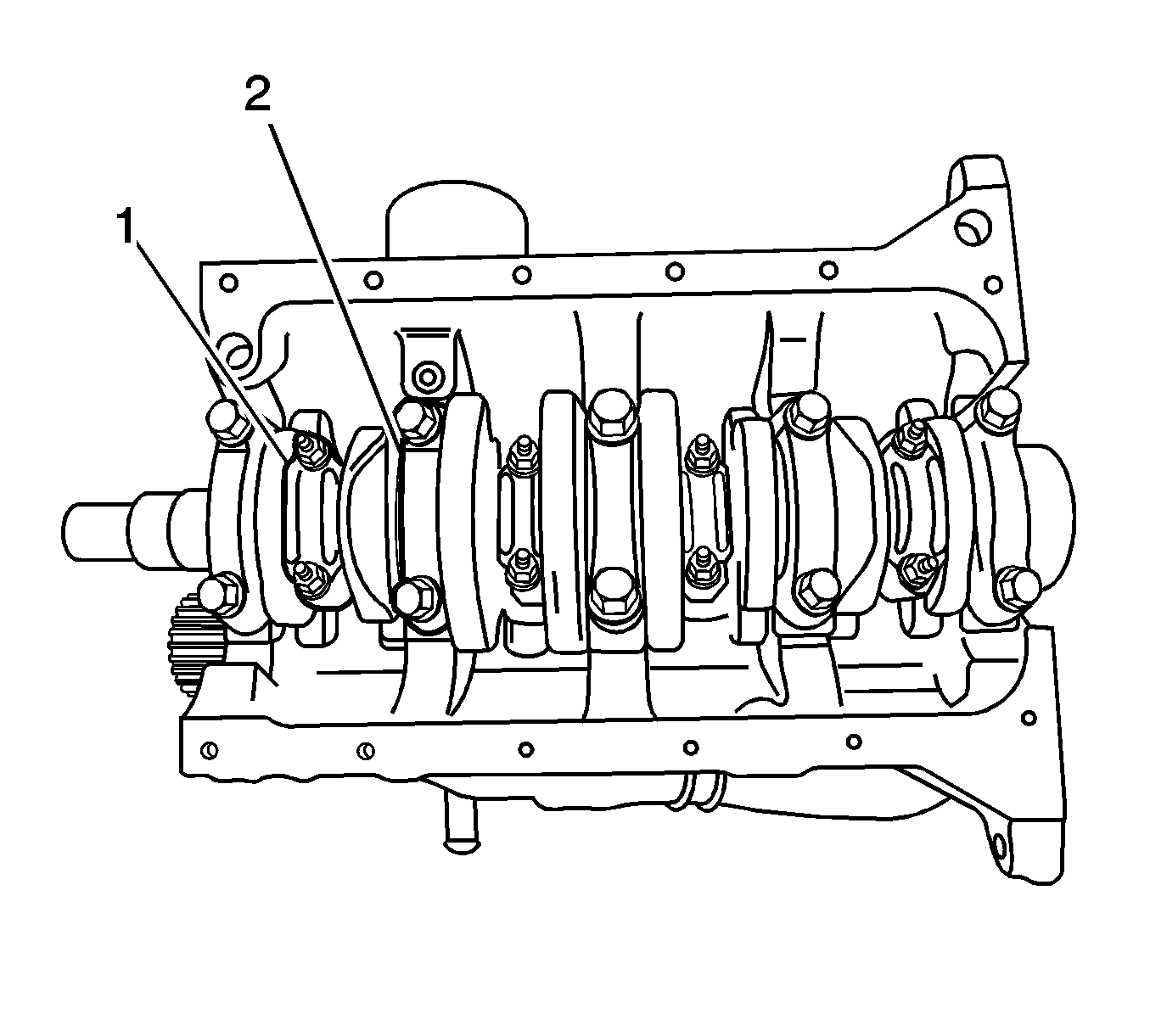
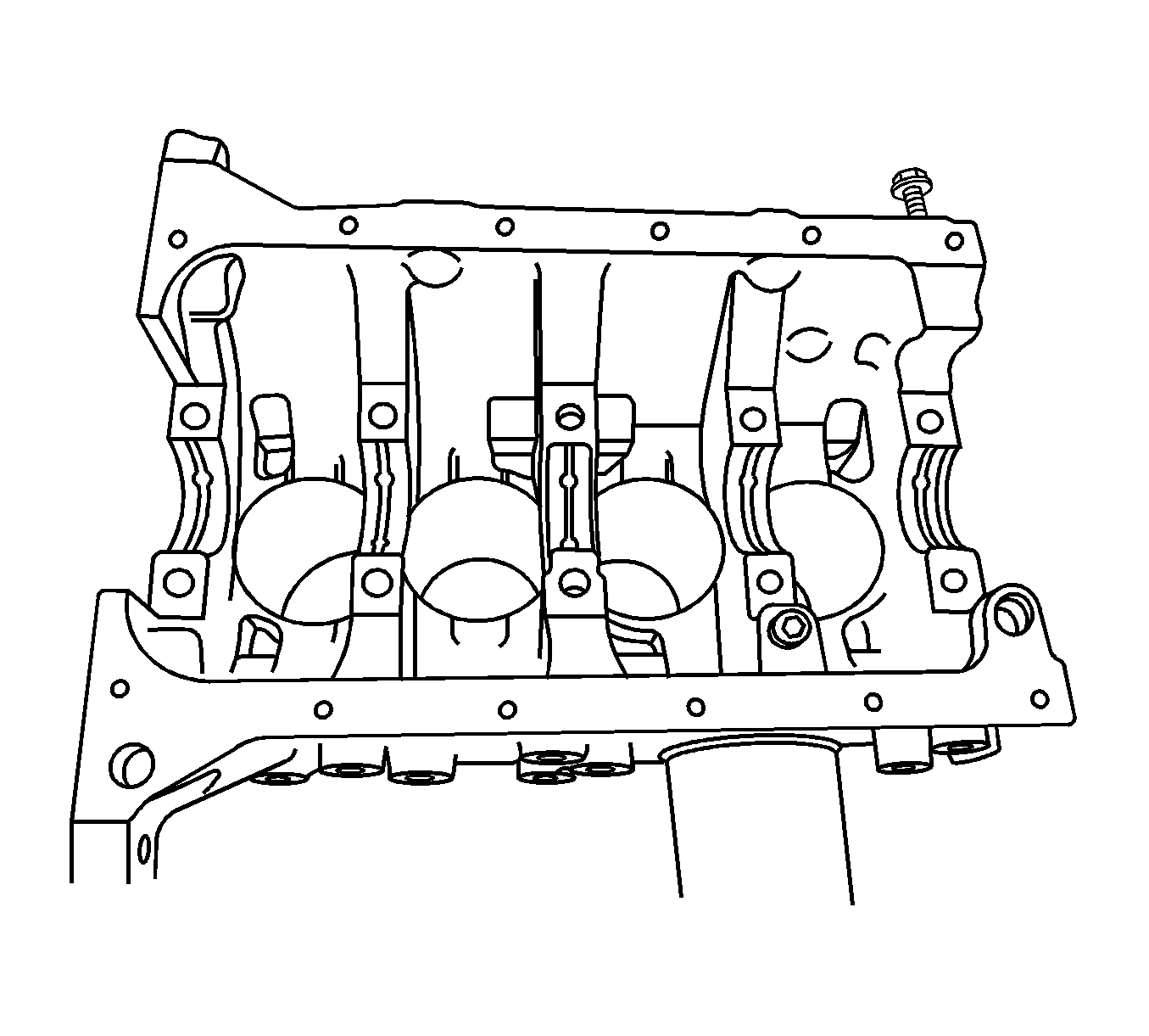
- Mark the order of the rod bearing caps.
- Remove the connecting rod cap nuts (1) for all of the pistons.
- Remove the connecting rod bearing caps and the lower connecting rod bearing.
- Remove the upper connecting rod bearing.
- Mark the order of the crankshaft bearing caps.
- Remove the crankshaft bearing cap bolts (2).
- Remove the crankshaft bearing cap.
- Remove the crankshaft bearings from the crankshaft bearing caps.
- Remove the crankshaft.
- Remove the crankshaft bearings from the engine block.
- Clean the parts, as necessary.
Assembly Procedure
- With the crankshaft and the bearings in place, plastic gage all bearing clearances. Refer to Piston, Connecting Rod, and Bearing Cleaning and Inspection .
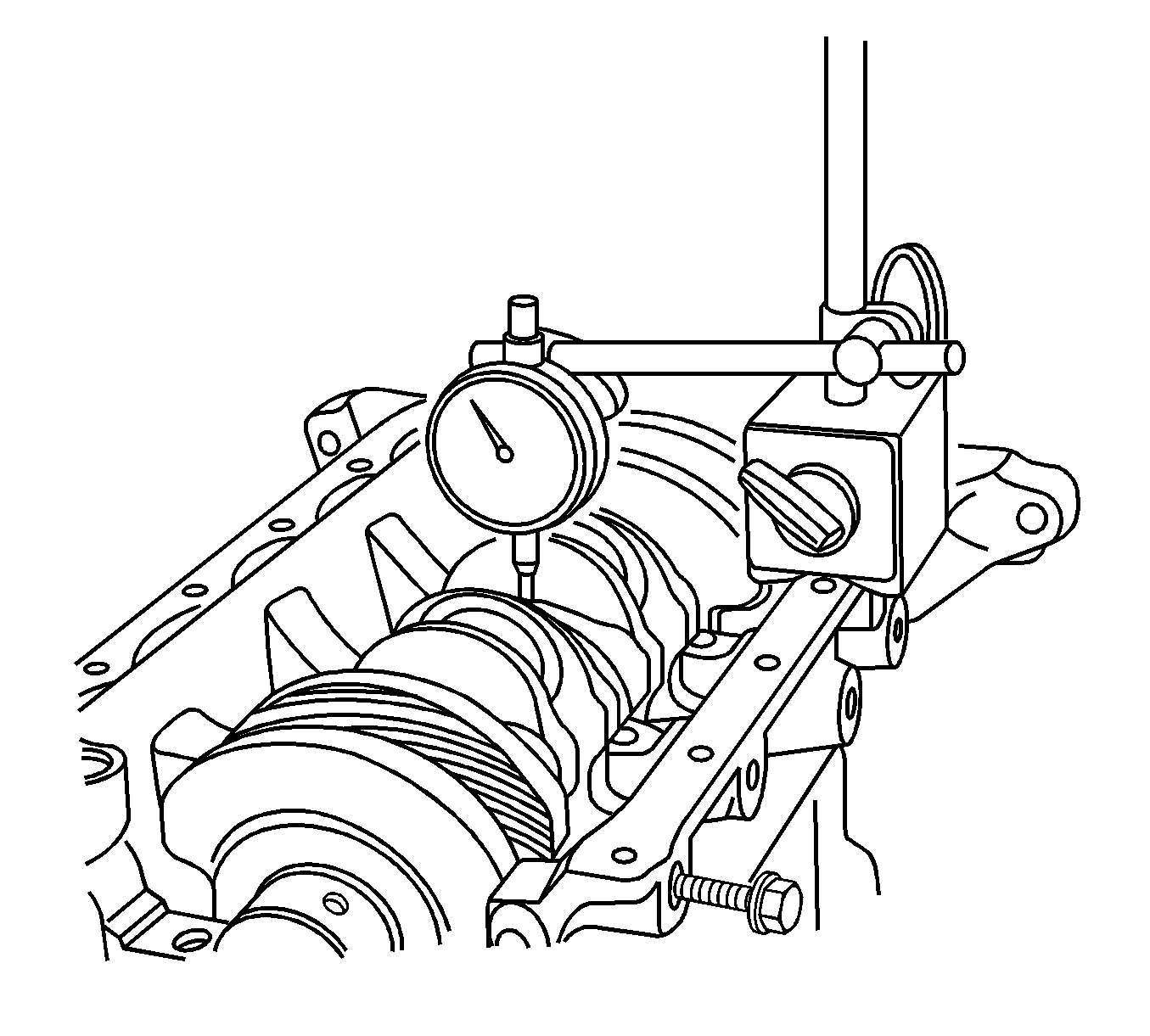
- Inspect the crankshaft end play with the crankshaft bearings installed.
- Check the permissible crankshaft end play. Refer to Engine Mechanical Specifications .
- With the crankshaft mounted on the front and the rear crankshaft bearings, inspect the middle crankshaft journal for permissible out-of-round, runout. Refer to Engine Mechanical Specifications .
- Coat the crankshaft bearings with engine oil.
- Apply a bead of adhesive sealing compound to the grooves of the rear crankshaft bearing cap.
- Install the crankshaft bearings in the engine block.
- Install the crankshaft.
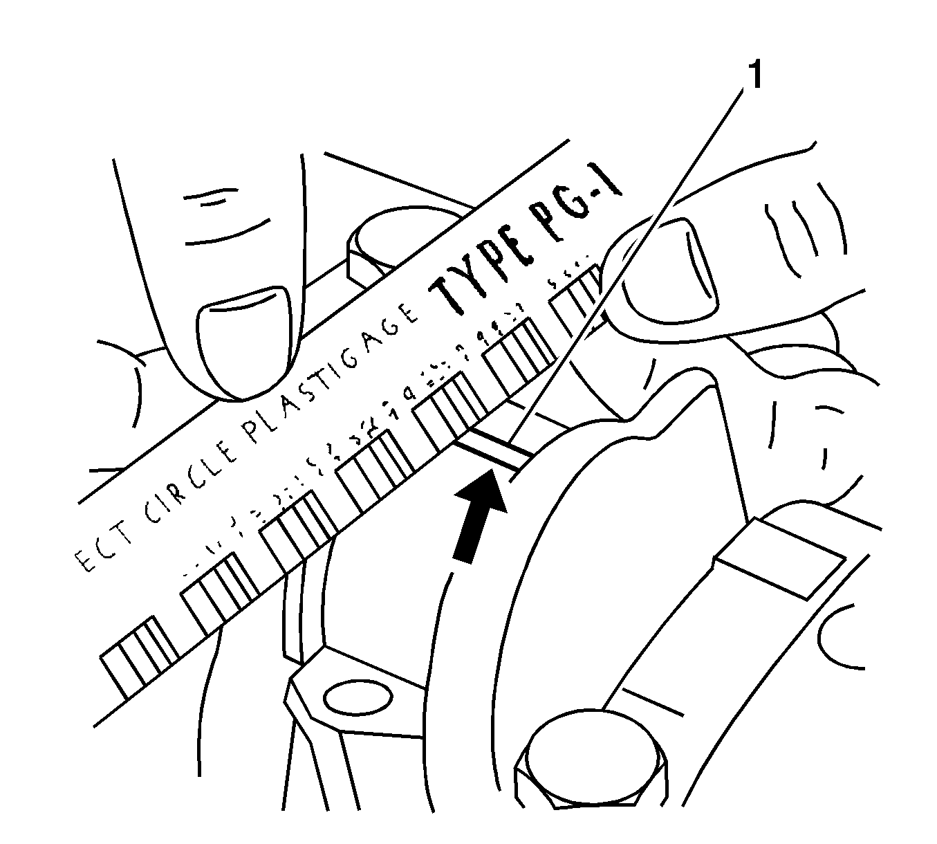
- Inspect all of the crankshaft bearing clearances using a commercially available plastic gaging--ductile plastic threads.
- Cut the plastic gaging threads to the length of the bearing width. Lay them between the crankshaft journals and the crankshaft bearings.
- Install the crankshaft bearings to the crankshaft bearing caps.
- Install the crankshaft bearing caps bolts (2).
- Remove the crankshaft bearing caps.
- Using a ruler, measure the width of the flattened plastic thread of the plastic gaging. Plastic gaging is available for different tolerance ranges.
- Inspect the bearing clearances for permissible tolerance ranges. Refer to Engine Mechanical Specifications .
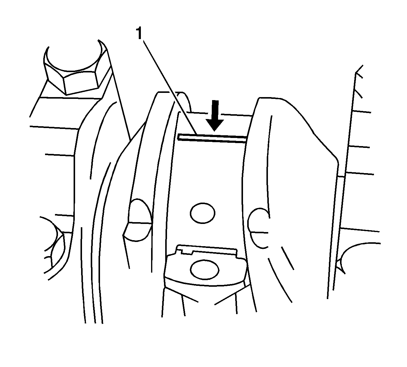
Important: Grease the crankshaft journals and lubricate the crankshaft bearings slightly so that the plastic gaging thread does not tear when the crankshaft bearings are removed.
Notice: Do not reuse crankshaft bearing cap bolts. Failure to replace the crankshaft bearing cap bolts can lead to crankshaft bearing cap bolt breakage or crankshaft bearing failure. A broken crankshaft bearing bolt can lead to extensive engine damage.
Notice: Refer to Fastener Notice in the Preface section.
Tighten
Tighten the crankshaft bearing cap bolts to 57 N·m (42 lb ft).