Leak Testing the Refrigeration System
Perform a refrigerant leak test on the refrigeration system whenever
one of the following conditions exist:
| • | A leak is suspected due to a system indication of a low charge. |
| • | After any service operation which disturbs the components, lines
or connections. |
Important: Vehicles equipped with an early warning system for low refrigerant may
set low refrigerant codes.
Many methods and special tools are available for leak testing. Always
use care and diligence, no matter which tool you are using.
Electric Halogen Leak Detector
Tools Required
J 39400 Kent-Moore
Electric Halogen Leak Detector
The J 39400
is the
most useful tool for locating refrigerant leaks. The J 39400
is a small unit which operates on 12V DC.
The J 39400
provides an
audible signal which increases in frequency as one of the following refrigerants
is detected:
The J 39400
has 3
settings:
The gross leak setting is used for isolating very large leaks which
you have already found using one of the other 2 settings. Ensure that the J 39400
is properly calibrated,
per the included instructions. Use the proper setting for the type of refrigerant
system that you are testing. Before you begin the test, ensure that the refrigerant
system is sufficiently charged for leak testing. Do this by measuring the
static pressure with a gauge set. Readings in the range of 60-100 psig
are acceptable in order to conduct a leak test.
The most common leaks are found at the refrigerant fittings or connections.
This may be caused by one of the following conditions:
| • | Lack of lubricant on the O-rings |
| • | Dirt/debris across the O-ring |
Even the smallest piece of lint from cotton gloves or a shop cloth can
create a leak path across an O-ring.
In order to successfully use this leak detector, or any other electronic
leak detector, perform the following steps:
| • | Use the proper scan rate. |
| • | Follow the manufacturer's instructions regarding the following
areas: |
Use this procedure in order to test the following areas:
| • | The low and high side sensors |
| • | The evaporator inlet and outlet |
| • | The accumulator dryer inlet and outlet |
| • | The condenser inlet and outlet |
| • | All brazed and welded areas |
| • | Areas that show signs of damage |
| • | The compressor rear head |
Important: Halogen leak detectors are sensitive to the following solutions that
are used in vehicles:
| • | Windshield washing solution |
Always follow the refrigerant system around in a continuous path so
that you do not miss any potential leak areas. Test all of the above areas
in order to assure that the entire system is leak free, even when you have
already found one leak.
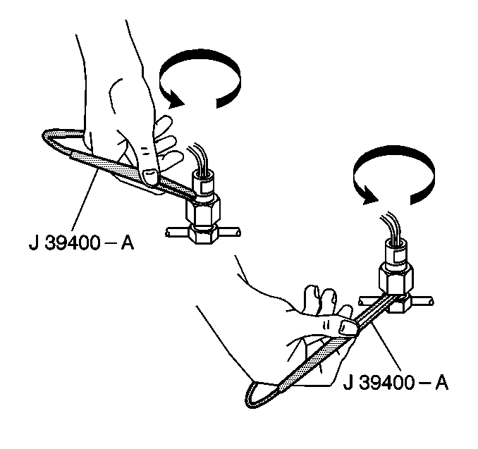
Completely circle each joint, using the following guidelines:
| • | Move at 1-2 in per second. |
| • | Keep the tip of the probe as close to the surface as possible. |
| | Keep the tip not more than ¼ in away from the surface. |
| | Do not block the air intake. |
A leak is indicated when the audible tone goes from a steady 1-2 clicks
per second to a solid alarm. The balance knob should be adjusted frequently
in order to maintain the 1-2 clicks per second rate.
Fluorescent Leak Detector
Tools Required
Important:
| • | J 41447 has
been developed to be used only with the following types of vehicles: |
| - | R-134a-equipped vehicles |
| - | Vehicles that have been retrofitted from R-12 to R-134a |
| • | Only J 41447
is recommended for use in the R-134a system. |
| | Use of any other products may cause the following conditions: |
| - | Affect system reliability |
| - | Cause premature compressor failure |
| • | Use only a ¼ oz charge of J 41447
. |
| | Larger amounts may compromise the reliability of the A/C system. |
| • | After adding J 41447
, clean the residual dye off of the service valves and surfaces. This
will prevent a false diagnosis. |
| | Use GM Engine Degreaser GM P/N 1050436 or
the equivalent. |
R-134a refrigerant is different from R-12 refrigerant which was used
in the past. R-134a may require additional methods in order to detect leaks.
The differences between R-134a and R-12 are listed below:
| • | The R-134a molecule is smaller than the R-12 molecule. |
| | This allows the R-134a molecule to leak through smaller openings. |
| • | The R-134a does not contain chlorine. |
| | The electronic leak detectors find chlorine easy to identify. |
Use the tracer dye method in conjunction with the electronic leak detector.
This will allow you to discover smaller leaks which may be undetected using
the electronic leak detector. R-134a tracer dye requires time. Depending
upon the rate of the leak, the leak may take up to 7 days in order
to become visible.
Dye Injection
| • | You can inject charged systems with tracer dye by using J 41436-1
, along with the instructions
provided. |
| • | For discharged systems, add the tracer dye in one of the following
ways: |
| - | Add the tracer dye to a replaced component. |
| - | Add the tracer dye using the ACR4 unit. |
Liquid Leak Detectors and Pressure Testing
Liquid/bubbles leak detectors have very limited usefulness, due to the
following conditions:
| • | The restricted visibility of today's refrigerant systems |
| • | The lack of sensitivity of today's refrigerant systems |
Service Ports/Access Valves
The primary seal for the service ports is the sealing cap. This cap
contains a specially designed O-ring or gasket which provides a leak-free
seal. A loss of refrigerant charge will result if one of the following situations
exists:
| • | The sealing cap is loose. |
| • | The sealing cap is missing. |
| • | The wrong sealing cap is used. |
Evaporator Core
One of the most difficult leaks to find is a leak in the evaporator
core. Perform the following steps in order to leak test the evaporator core:
- Turn the blower fan to the HIGH position for 15 seconds
or more.
Shut the blower fan off.
- Wait for 10 minutes.
- Remove the following components, if the components are accessible:
| • | The blower fan power module |
- If the above components are not removable, inspect the condenser
drain tube for moisture.
If the condenser drain tube is dry, use the condenser drain tube instead.
- Insert the leak detector probe into the power resistor/relay block
opening if you removed the power resistor/relay block.
If you did not remove this component, insert the leak detector probe
into the drain tube.
If the detector goes to a solid alarm, you have found a leak.
- Use a flashlight to visually inspect the core face for evidence
of refrigerant oil.
Note that on Refrigerant-134a systems the lubricant is water-soluble,
so no evidence of oil is likely, even if there is a leak.
Compressor Shaft Seal
- Blow shop air in the following areas for at least 15 seconds:
| • | Behind the compressor clutch/pulley |
| • | In front of the compressor clutch/pulley |
- Wait 1-2 minutes.
- Probe the area in front of the pulley.
You have detected a leak if the detector goes to a solid alarm.
