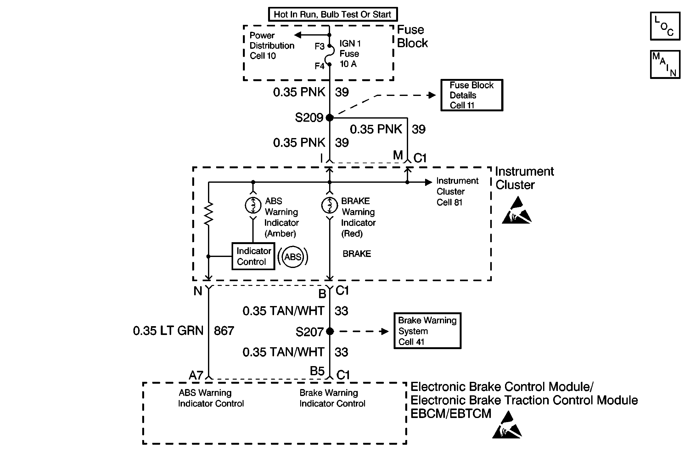
Circuit Description
DTC C1211 tests the state of the ABS warning indicator. DTC C1211 identifies a situation in which the driver could not be warned of a system malfunction by the ABS warning indicator or the ABS warning indicator is always on. Due to an integral lamp driver module within the instrument panel cluster the EBCM/EBTCM must provide a ground in order to turn the amber ABS warning indicator off. Because of the circuitry in the Lamp Driver Module (LDM) only external malfunctions are detected. As a result the integral LDM itself is not diagnosable. Only the control line to the EBCM/EBTCM is diagnosable. In the event of an open CKT 867 the ABS warning indicator remains on at all times due to the loss of ground at the integral LDM input. If the control line shorts to ground the ABS warning indicator remains off due to grounding the integral LDM input.
Note: This code is for basic ABS systems and will not show if vehicle is equipped with TCS (Traction Control System).
Conditions for Setting the DTC
DTC C1211 does not set if the vehicle is equipped with TCS.
DTC C1211 sets only during one of the following conditions:
| • | The three second bulb check. |
| • | The amber ABS warning indicator turns on. |
A malfunction exists if the EBCM/EBTCM cannot control the ABS warning indicator for two seconds.
Action Taken When the DTC Sets
| • | A malfunction DTC stores. |
| • | The ABS does not disable. |
Conditions for Clearing the DTC
| • | The condition responsible for setting the DTC no longer exists and the Scan Tool Clear DTCs function is used. |
| • | 100 drive cycles pass with no DTC detected. |
Diagnostic Aids
The following conditions may cause an intermittent malfunction:
| • | A poor connection |
| • | Rubbed-through wire insulation |
| • | A broken wire inside the insulation |
Use the Scan Tool Lamp Test function to command the indicator on while looking for an intermittent malfunction in the ABS warning indicator circuitry.
Use the enhanced diagnostic function of the Scan Tool in order to measure the frequency of the malfunction. Refer to the Scan Tool manual or Scan Tool Diagnostics located in this section for the procedure.
Thoroughly inspect any circuitry that may be causing the intermittent complaint for the following conditions:
| • | Backed out terminals |
| • | Improper mating |
| • | Improperly formed or damaged terminals |
| • | Poor terminal-to-wiring connections |
| • | Physical damage to the wiring harness |
Important: Zero the J 39200 test leads before making any resistance measurements.
Step | Action | Value(s) | Yes | No | ||||||
|---|---|---|---|---|---|---|---|---|---|---|
1 | Was the Diagnostic System Check performed? | -- | Go to Step 2 | |||||||
2 |
Can the amber ABS warning indicator be turned on and flashed? | -- | Go to Step 23 | Go to Step 3 | ||||||
3 |
Does the amber ABS warning indicator turn on and stay on? | -- | Go to Step 4 | Go to Step 10 | ||||||
4 |
Are there any other DTCs present? | -- | Go to the appropriate DTC table | Go to Step 5 | ||||||
5 |
Is the amber ABS warning indicator on? | -- | Go to Step 6 | Go to Step 8 | ||||||
6 |
Is the resistance within the specified range? | 0-2ohms | Go to Step 7 | Go to Step 20 | ||||||
7 |
Is any voltage present at the 24-way EBCM/EBTCM harness connector C1 terminal A7? | -- | Go to Step 21 | Go to ABS Indicator Always On . | ||||||
8 |
Are there signs of poor terminal contact, corrosion, or a damaged terminal? | -- | Go to Step 19 | Go to Step 9 | ||||||
9 |
Does DTC C1211 reset? | -- | Go to Step 22 | |||||||
10 |
Do the remaining instrument panel cluster warning indicators operate properly? | -- | Go to Step 11 | Go to Step 13 | ||||||
11 |
Does the amber ABS warning indicator turn on? | -- | Go to Step 8 | Go to Step 12 | ||||||
12 |
Is continuity present between the 24-way EBCM/EBTCM harness connector C1 terminal A7 and ground? | -- | Go to Step 18 | |||||||
13 |
Is the fuse open? | -- | Go to Step 14 | Go to Step 16 | ||||||
14 | Use the J 39200 in order to measure the resistance between CKT 39 and ground. Is continuity present between CKT 39 and ground? | -- | Go to Step 15 | Go to Step 17 | ||||||
15 | Repair the short to ground in CKT 39. Is the repair complete? | -- | Go to Step 17 | -- | ||||||
16 | Repair the open in CKT 39. Is the repair complete? | -- | -- | |||||||
17 | Replace the IGN 1 fuse (10A). Is the repair complete? | -- | -- | |||||||
18 | Repair the short to ground in CKT 867. Is the repair complete? | -- | -- | |||||||
19 | Repair the 24-way EBCM/EBTCM connector C1. Is the repair complete? | -- | Go to Step 9 | -- | ||||||
20 | Repair the open or high resistance in CKT 867. Is the repair complete? | -- | -- | |||||||
21 | Repair the short to voltage in CKT 867. Is the repair complete? | -- | -- | |||||||
22 | Replace the EBCM/EBTCM. Is the repair complete? | -- | -- | |||||||
23 | The system is functioning properly at this time. The malfunction may be intermittent or not present at the time of testing. Is a concern still present? | -- | Go to Diagnostic Aids |
