Circuit Description
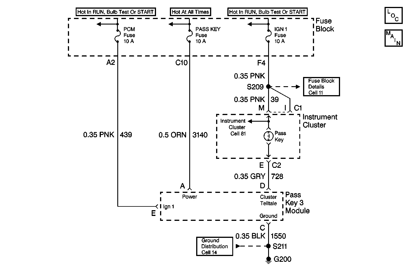
The PASS-Key® III (VTD) module provides the control for the pass key telltale on the instrument cluster.
When the ignition switch is turned to the ON position, with a valid key transponder pellet, the VTD module will output a low voltage level for 2 seconds on pin D to provide a ground for the Pass Key telltale and illuminate the bulb. This is a 2 second bulb test mode that indicates a valid key code. The vehicle will start and run under this condition.
If an invalid key is used to turn the ignition ON, the VTD module outputs a Pulse Width Modulated signal at 1 Hz. and a 50 % duty cycle to flash the telltale. An invalid key has a transponder value that has not been learned by the VTD module. Under this condition the vehicle will not start and run.
The VTD module will flash the security telltale at 2 Hz. when an illegitimate key is used to turn the ignition ON, or when the module detects a problem with the transponder reader. A key code is illegitimate if the key code is zero or cannot be read. Under this condition the vehicle will not start and run.
A history code B0689 will always be stored in memory. When the ignition is turned OFF, the VDT module still has battery power on CKT 3140, and continues to perform self diagnostic routines for 10 seconds. During the diagnostic routines after ignition OFF, the IP cluster is not powered therefore the telltale appears as an open. Upon the next ignition ON cycle, the IP cluster is powered and the VDT module will see the telltale is present and will only store the history B0689.
Conditions for Setting the DTC
| • | DTC B0689 indicates that an open exists in the security system indicator circuit 728. |
| • | The above condition will be set within 1 second of determining that the output has failed. |
| • | A history B0689 will always be present. (see above) |
Action Taken When the DTC Sets
| • | The VTD module enters the fail enable mode and allows the vehicle to start and run. |
| • | The VTD module stores a DTC B0689 in memory. |
Conditions for Clearing the DTC
| • | The conditions for the fault are no longer present. |
| • | A history DTC will always be present. |
| • | The use of the scan tool. |
Diagnostic Aids
Check the following conditions if a history or intermittent DTC is indicated:
| • | A poor connection at the VTD module or IP. Inspect the wiring harness connectors for backed out terminals, improper mating, improperly formed or damaged terminals, and poor terminal to wire connections. |
| • | A damaged wiring harness. Inspect the wiring harness for damage. If the wiring harness appears to be in good condition, observe the display on the DMM while moving the connectors and wiring harnesses related to the VTD module and IP. |
| • | For additional information, refer to Intermittents and Poor Connections Diagnosis in Wiring Systems. |
Check the following before replacing the PASS-Key® III module:
| • | Test the ground circuit at terminal C (BLK). Perform a voltage drop test, refer to Testing for Voltage Drop in Wiring Systems. Typical voltage drop readings are 100 mV or less. When measuring the resistance it should measure at close to 0 (zero) ohms. |
| • | Test the power circuits at terminal A (ORN Wire) and terminal E (PNK wire). |
Test Description
The following numbers refer to the step numbers on the diagnostic table:
-
B0686 or B0688 could be caused by a short to voltage in CKT 728.
-
B0687 or B0689 could be caused by an open or a short to ground in CKT 728.
-
The module may be at fault if no trouble is found in CKT 728 or if there are no intermittent faults found.
Step | Action | Value(s) | Yes | No | ||||||||||||||
|---|---|---|---|---|---|---|---|---|---|---|---|---|---|---|---|---|---|---|
1 | Was the PASS Key Diagnostic System Check performed? | -- | ||||||||||||||||
Is the DTC shown B0686 or B0688? | -- | |||||||||||||||||
3 | Inspect CKT 728 for a short to voltage. Is the repair complete? | -- | -- | |||||||||||||||
Is the DTC shown B0687 orB0689? | -- | |||||||||||||||||
5 | Inspect CKT 728 for the following conditions:
Is the repair complete? | -- | -- | |||||||||||||||
6 |
Are any of the following codes present?:
| -- | ||||||||||||||||
7 | Inspect CKT 728 for an intermittent fault. Was there an intermittent fault found and repaired? | -- | ||||||||||||||||
Replace the PASS Key III module. Refer to PASS-Key III Module Replacement Is the repair complete? | -- | -- | ||||||||||||||||
9 | Turn the key ON. Are any of the IP guages or lights working? | -- | Go to Step 10 | |||||||||||||||
10 | Inspect the IP PASS KEY telltale bulb. Is the bulb burned out? | -- | Go to Step 11 | Go to Step 5 | ||||||||||||||
11 | Replace the IP PASS KEY telltale bulb. Is the repair complete? | -- | Go to Step 6 | -- |
