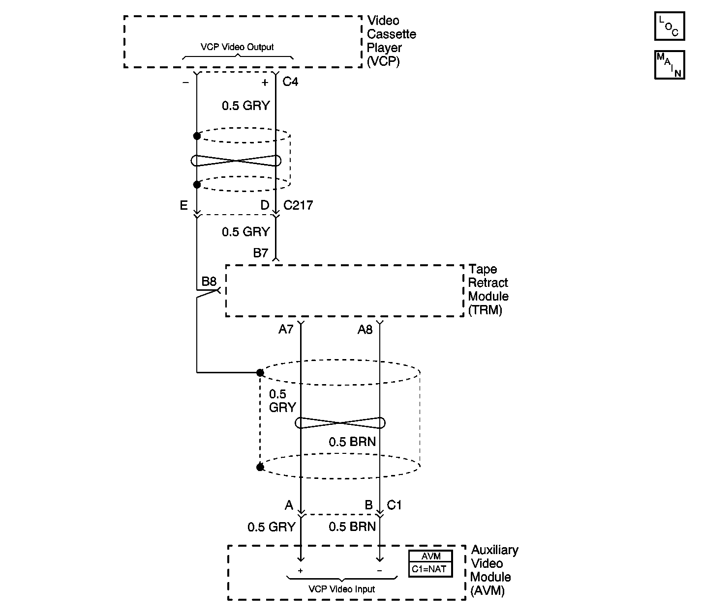
Circuit Description
The Video Cassette Player (VCP) plays pre-recorded VHS tapes. The Auxiliary Video Module (AVM) receives the video signal generated by the VCP. When the AVM switch is set to VCP mode, the AVM routes the VCP video signal to the video screen. Then, the video screen produces images based on this video signal (when the ignition switch is on and the video screen is in the down position.)
Diagnostic Aids
| • | Check for the following conditions: |
| - | An open in GRY and/or BRN wires between the VCP and the AVM. |
| - | A faulty VCP. |
| - | A faulty AVM. |
| • | An intermittent failure may be very difficult to detect and to diagnose accurately. Faulty electrical connections or wiring causes most intermittent problems. When an intermittent condition is suspected, check the suspected circuits for the following conditions: |
| - | Poor mating of connector halves or backed out terminals. |
| - | Improperly formed or damaged terminals. |
| - | Wire chafing. |
| - | Poor wire to terminal connections. |
| - | Dirty or corroded terminals. |
| - | Damage to connector bodies. |
| - | Wire broken inside the insulation. |
Test Description
The number(s) below refer to the step number(s) on the diagnostic table.
-
Checks the AVM for correct setting.
-
Checks for a backed-out video out connector at the VCP.
-
Determines whether the video screen or the VCP is faulty, by means of an external video output source.
-
Determines whether the video screen or the VCP is faulty, by means of an external video input source.
-
Verifies repairs made to the VES.
Step | Action | Value(s) | Yes | No |
|---|---|---|---|---|
Is the Auxiliary Video Module (AVM) set to the VCP position? | -- | Go to Step 3 | Go to Step 2 | |
2 | Set the AVM to VCP mode and verify operation. Is the action complete? | -- | System OK | -- |
Check the Video Cassette Player (VCP) connector C4 (video out). Is the VCP connector C4 fully seated? | -- | Go to Step 5 | Go to Step 4 | |
4 | Reconnect VCP connector C4 and check system operation. Is the repair complete? | -- | Go to Step 9 | -- |
Does the external source of video produce an image on the video display? | -- | Go to Step 7 | Go to Step 8 | |
Does the VCP produce video on external source of video display? | -- | Go to Step 8 | Go to Step 7 | |
7 | Replace the VCP. Refer to Video Cassette Player Replacement . Is the repair complete? | -- | Go to Step 9 | -- |
8 |
Is the repair complete? | -- | Go to Step 9 | -- |
Does the VES operate normally? | -- | System OK |
