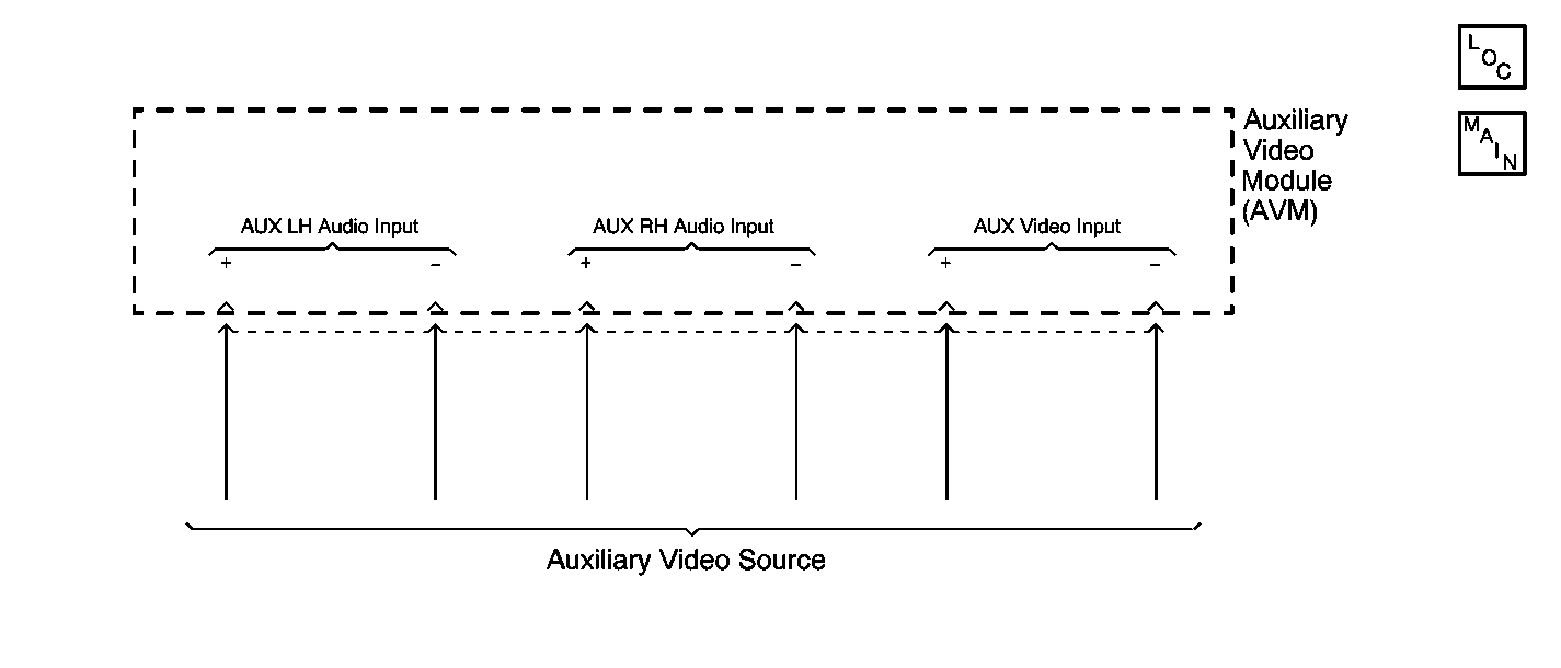
Circuit Description
The Auxiliary Video Module (AVM) allows the user to connect an auxiliary source of video and audio through RCA-style input jacks. When the AVM switch is set to AUX mode, the AVM routes the video signal from the auxiliary source of video to the video screen. Then, the video screen produces images based on this video signal (when the ignition switch is on and the video screen is in the down position.)
Diagnostic Aids
| • | Check for the following conditions: |
| - | A faulty auxiliary video device. |
| - | A faulty AVM. |
| • | An intermittent failure may be very difficult to detect and to diagnose accurately. Faulty electrical connections or wiring causes most intermittent problems. When an intermittent condition is suspected, check the suspected circuits for the following conditions: |
| - | Poor mating of connector halves or backed out terminals. |
| - | Improperly formed or damaged terminals. |
| - | Wire chafing. |
| - | Poor wire to terminal connections. |
| - | Dirty or corroded terminals. |
| - | Damage to connector bodies. |
| - | Wire broken inside the insulation. |
Test Description
The number(s) below refer to the step number(s) on the diagnostic table.
-
Checks the AVM for correct setting.
-
Determines whether the auxiliary video/audio device is faulty or the AVM is faulty.
-
Verifies repairs made to the VES.
Step | Action | Value(s) | Yes | No |
|---|---|---|---|---|
Is the Auxiliary Video Module (AVM) set to the AUX position? | -- | Go to Step 3 | Go to Step 2 | |
2 | Set the AVM to AUX mode position and verify operation. Is the action complete? | -- | System OK | -- |
Connect a known-good auxiliary video/audio source into the AVM inputs. Does the known-good auxiliary video/audio source work with the Video Entertainment System (VES)? | -- | Go to Step 4 | Go to Step 5 | |
4 | Check the auxiliary video/audio source and verify VES operation. Is the action complete? | -- | System OK | -- |
5 | Replace the AVM. Refer to Audio/Video Interface Module Replacement . Is the repair complete? | -- | Go to Step 6 | -- |
Does the VES operate normally? | -- | System OK |
