For 1990-2009 cars only
Tools Required
J 43765 Stator Shaft Installer/Remover
Removal Procedure
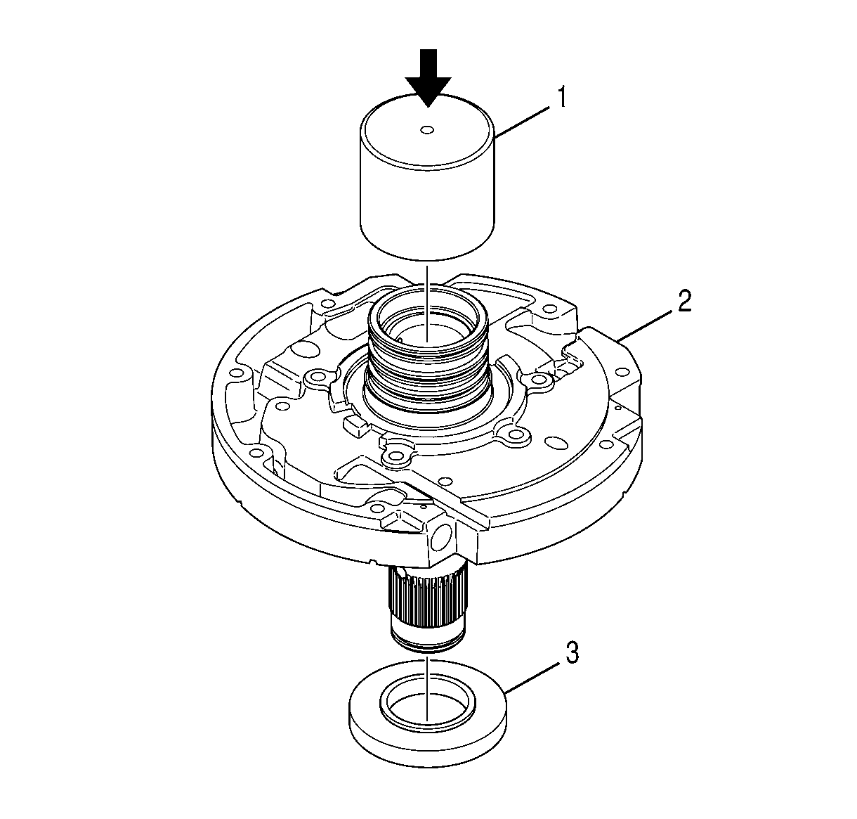
- Position the oil pump cover assembly (2) on a press bed so that the assembly is supported by wooden blocks and the stator shaft is facing down.
- Install the short end of J 43765-2 remover (1) into the rear of the oil pump cover assembly.
- Press the stator shaft from the oil pump cover assembly (2).
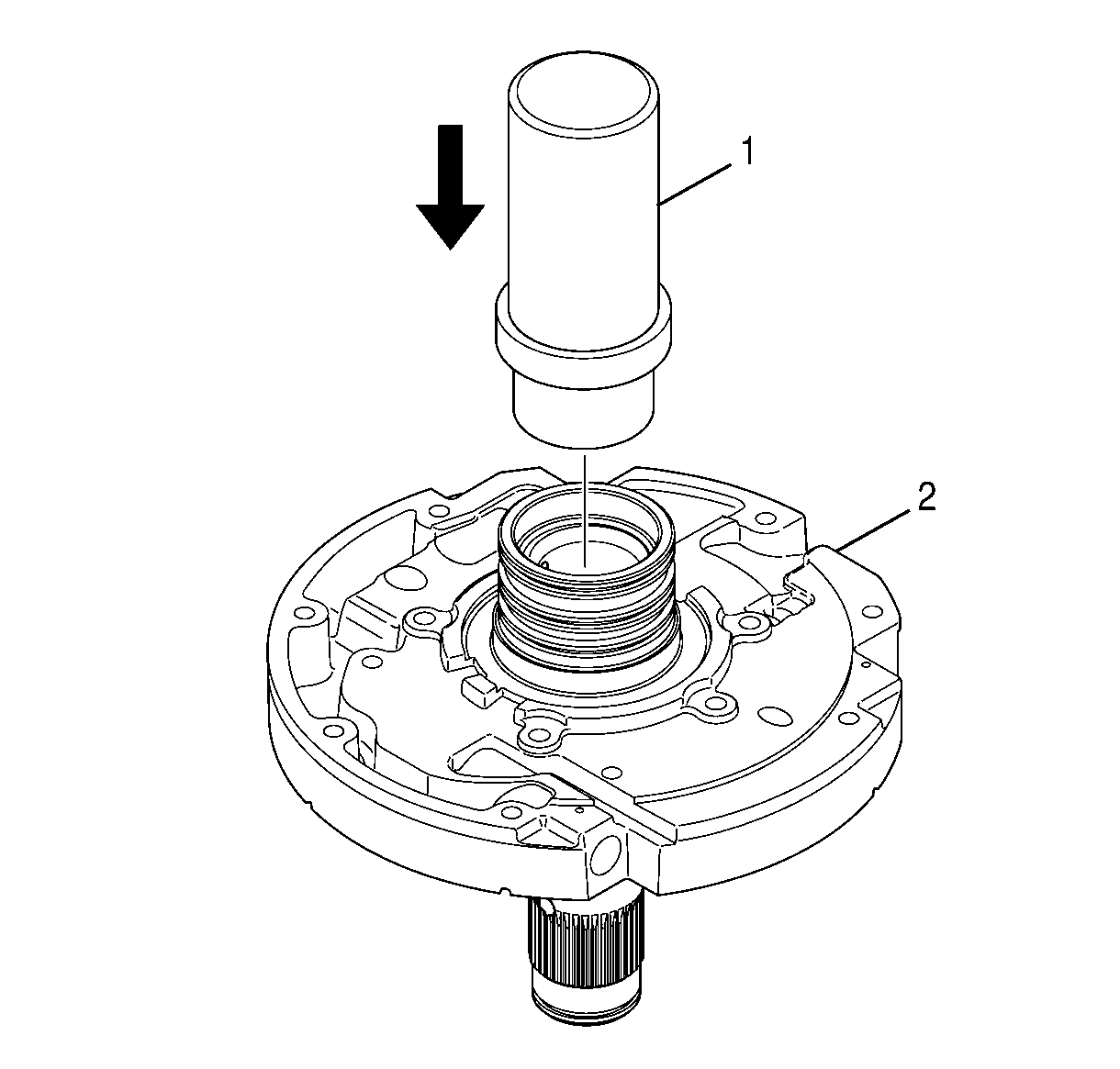
Important: Remove the needle bearing only if replacing both the bearing and the stator shaft.
Installation Procedure
- Position the oil pump cover (2) on the work table so that the rear hub is facing down.
- Align the stator shaft with the oil pump cover so that the stator shaft is centered over the oil pump cover and the rear of the stator shaft is facing down.
- Rotate the stator shaft (1) until the lowest and smallest hole in the stator shaft is aligned with the fluid passage (2).
- Gently tap the stator shaft into the oil pump cover until the oil pump cover holds the ground sleeve in a vertical position.
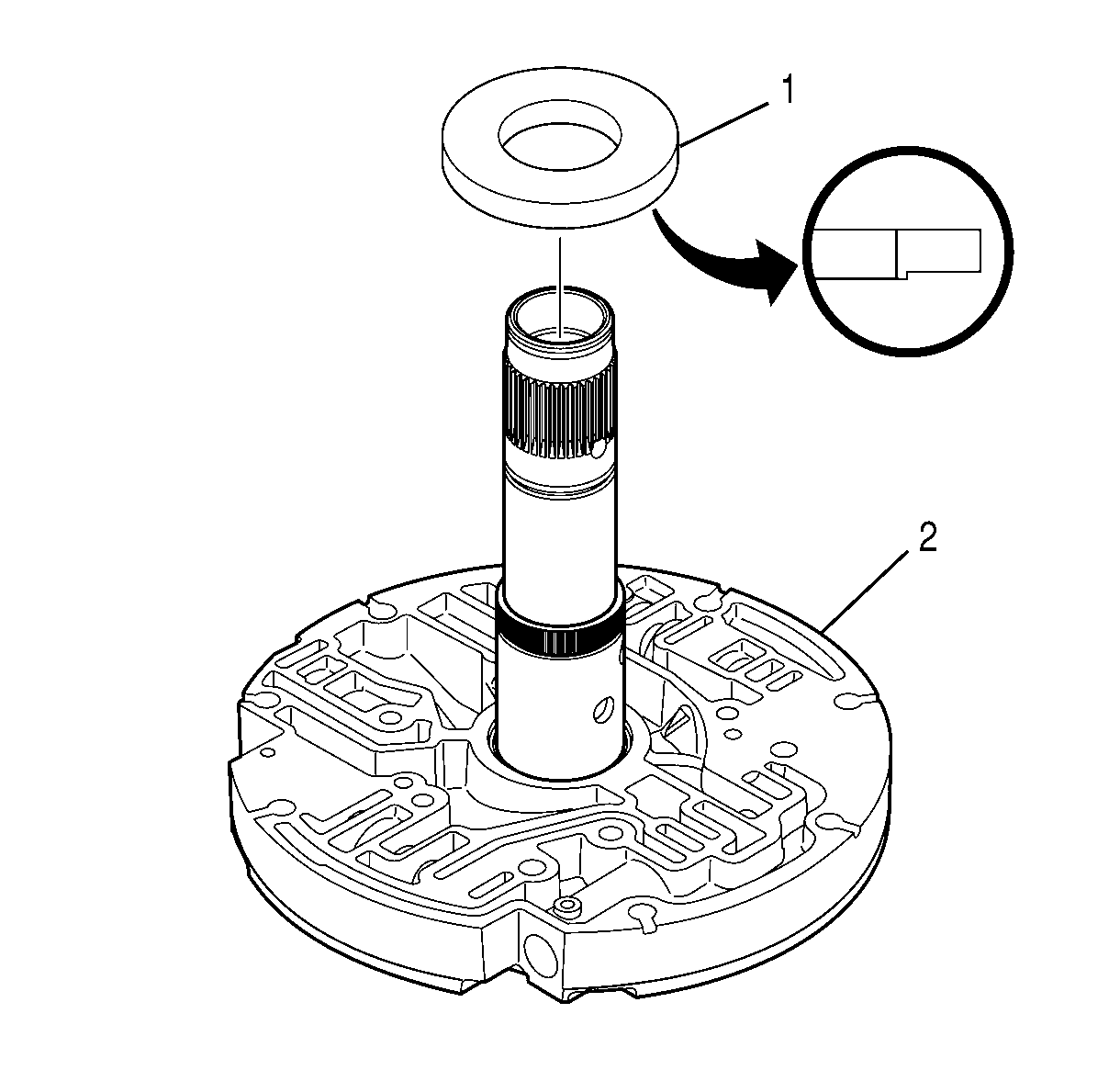
- Align J 43765-1 protector (1) so that the lip of the tool is downward.
- Install J 43765-1 protector (1) onto the stator shaft.
- While holding J 43765-1 protector (3) in place, turn over the oil pump cover assembly (2) and place J 43765-1 on a press.
- Install J 43765-3 installer (1) into the rear hub of the oil pump cover assembly (2).
- Press on J 43765-3 installer (1) until the stator shaft seats.
- Check the total indicated runout (TIR) of the stator shaft as follows:
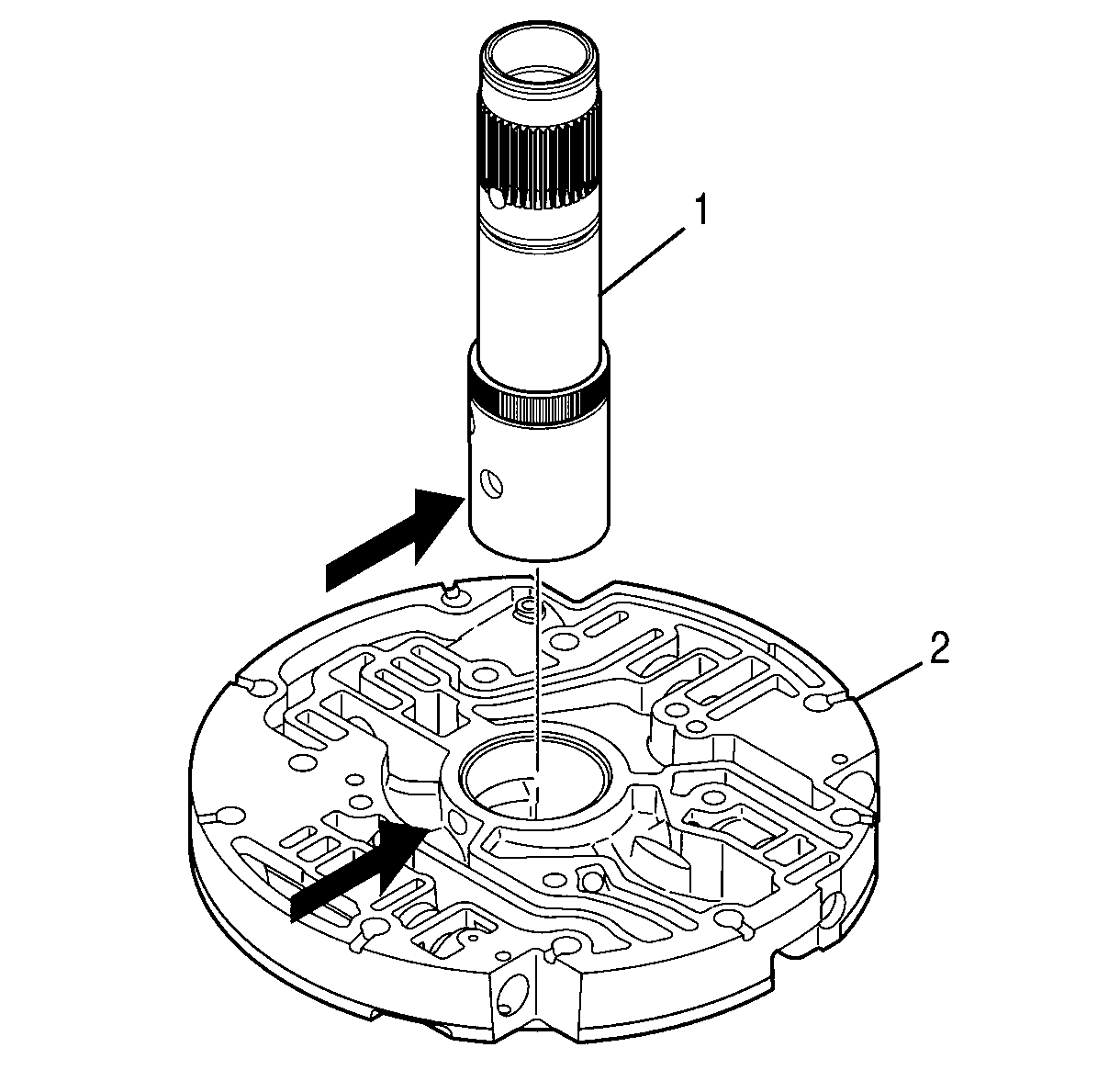
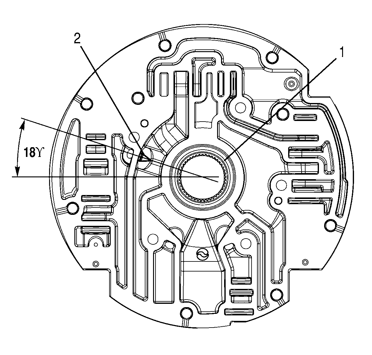
Important: The arrows on the drawing indicate the holes that must be aligned.
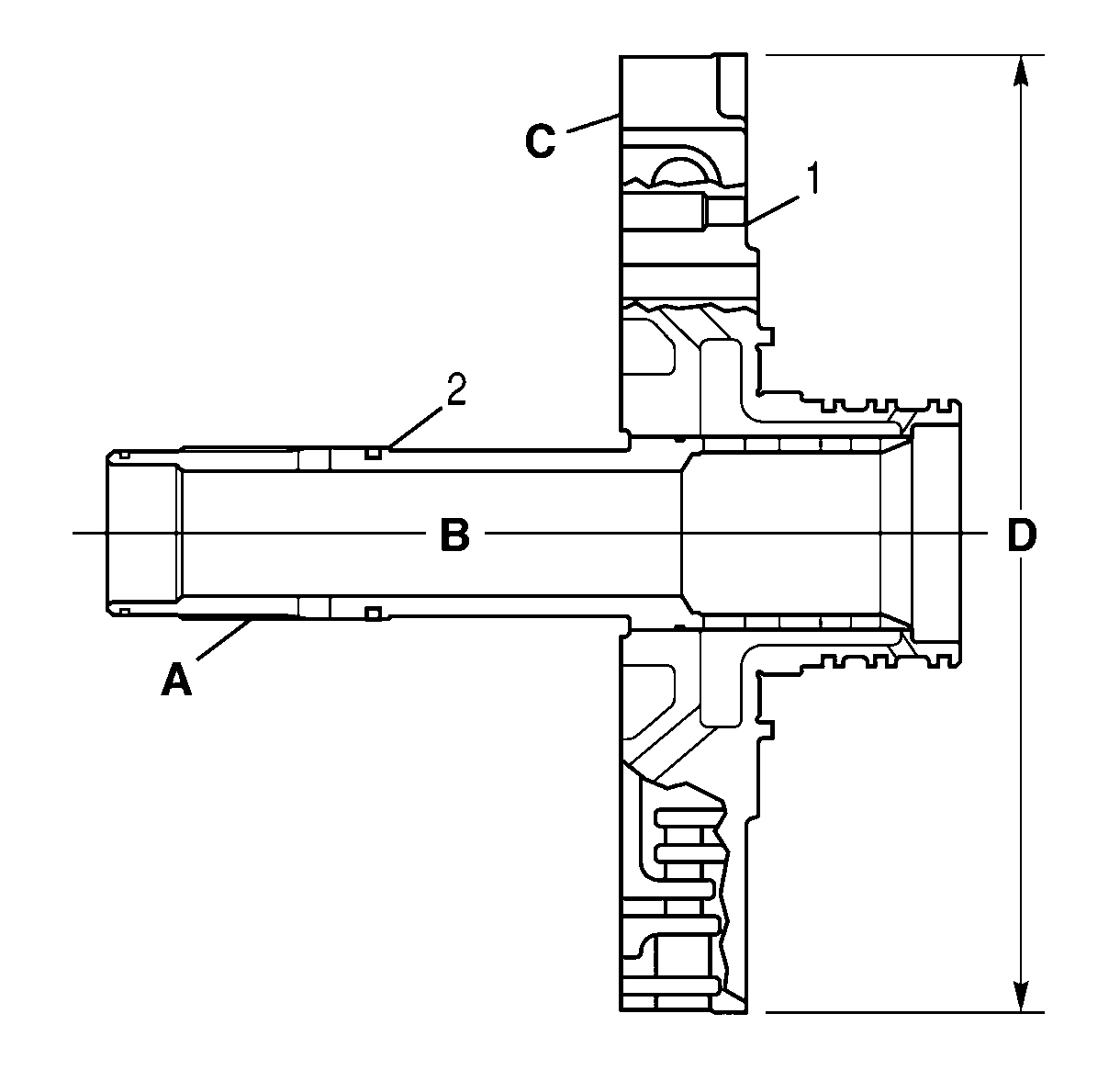
| 10.1. | Install the oil pump cover assembly (1) in a lathe, clamping on dimension D. |
| 10.2. | Use a dial indicator, to make sure the oil pump cover surface C is square with the dimension D. |
| 10.3. | Check the TIR along the stator shaft axis B at the stator shaft pitch diameter A. |
Specification
The TIR must not exceed 0.20 mm (0.008 in).
| 10.4. | Remove the oil pump cover assembly from the lathe. |
